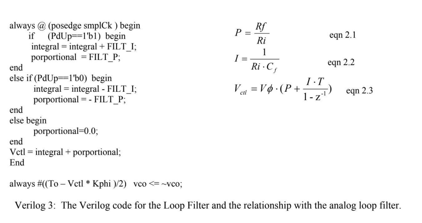
Hello, the attached photo is taken from the attached article,

The line bellow doesnt resemble any line on the right side, how it
describes the formula on the right?
1 | integral=integral+FILT_I |
Thanks
|
|
Forum: FPGA, VHDL & Verilog PI loop filter in Verilog
Du wurdest von Mikrocontroller.net auf diese Seite weitergeleitet. Zurück zu Mikrocontroller.net
Attached files:
Hello, the attached photo is taken from the attached article, The line bellow doesnt resemble any line on the right side, how it describes the formula on the right?
Thanks :
Edited by User
From what I understand about PID controllers is that the integral portion is just an accumulator. Which is why its integral = integral + FILT_I. Each time it adds the current value to the accumulator(integrator). The formulas on the right are for the analog filter in the article, which is made with an op amp. I'm not sure you're going to find a correlation between the two. Just my two cents. Hello, There are two variables, integral and proportional when clk=1 then integral decreases ,when clk=0 then it decreases. proportional toggles from negative to positive with the FILT amplitude. and both of them goes into vtcl with is the factor controlling the period of the VCO. how this logic represnt PID loop filter? Thanks :
Edited by User
Please log in before posting. Registration is free and takes only a minute.
Existing account
Do you have a Google/GoogleMail account? No registration required!
Log in with Google account
No account? Register here.
|
|