I have been giving a specification to derive 10MHz,5MHz and 1MHz from a
20MHz system clock. I am also supposed to design posedge and negedge
flags for all the three derived clocks.

I used a 4 bit counter which counted from 0-15 and the counter[0] gave
me the 10MHz clock signal and the counter [1] gave me the 5MHz signal. I
used another 5 bit counter which counted from 0-9. I made my 1MHz signal
register toggle for 0-9 each count, which gave me the 1MHz clock signal.

Now I am struggling to design the posedge and negedge flags for all
three of the clocks. I used a combination logic of posedge = a^!b; but I
could get the flags for 10MHz and 5MHz but couldn't extract my 1MHz
flags from this method.

I was suggested to use my two counters (4 bit and 5 bit) to easily
design the flags for all three of them. Kindly suggest on this

Thank you in advance and kind regards
Attached files:
-

clkgen_wf.PNG
2.8 KB
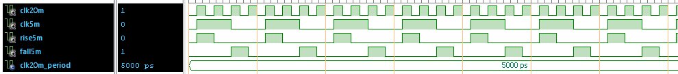
Sushma K. wrote:
> I have been giving a specification to derive 10MHz,5MHz and 1MHz from a
> 20MHz system clock. I am also supposed to design posedge and negedge
> flags for all the three derived clocks.
So in fact you do not need the clocks itself (its also known to be a bad
design practise to generate clocks that way). Insted you want to get
clock enables with those specifications.
Although for the 10MHz it is a simple flipflop toggeling (and its
negation) I would use shift registers in this way: for the 5MHz a 4 bit
shift register with reset value of binary 1000. This I would rotate with
each 20MHz clock by one to get this pattern:
1000 --> 0001 --> 0010 --> 0100 --> 1000 and so on...
And now the one ouput of this generator is bit 2 and the other is bit 0.

For the 1MHz this would be a 20 bit shift register with default value
10000000000000000000 and output at bit 10 and bit 0.

And for the 10MHz it is a 2 bit shift register with output on bit 1 and
bit 0.

And when you really need those three clocks they can easily be generated
the very same way...

In VHDL for the 5MHz generator this would look like the attached file.
Got the trick?
:
Edited by Moderator
Thank you, I got the idea. I am trying to derive the clock signals from
your way of using 4 bit shift registers. But I just used a 4bit shift
registers and I got a 10MHz signal. How can I get 5 MHz signal from the
same 4 bit shift registers. Please find my code here:

module shift_clk (

input clk,
input rst,
output clk_10

);

reg clk_10_reg;
reg [3:0] shift_reg;


always@(posedge clk or posedge rst)
begin
  if(rst==1'b1)
    begin
    clk_10_reg <= 1'b0;
    shift_reg <= 4'b1000;
    end
  else
    begin
    if(shift_reg == 4'b1000)
      begin
      clk_10_reg <= clk_10_reg;
      shift_reg[0] <= shift_reg[3];
      shift_reg[1] <= shift_reg[0];
      shift_reg[2] <= shift_reg[1];
      shift_reg[3] <= shift_reg[2];
      end
    else
      begin
       clk_10_reg <= ~clk_10_reg;
      shift_reg  <= shift_reg;
      end

    end
   end

    assign clk_10 = clk_10_reg;


endmodule
Please log in before posting. Registration is free and takes only a minute.
Existing account
Do you have a Google/GoogleMail account? No registration required!
Log in with Google account
Log in with Google account
No account? Register here.