Recently I am learn something about UA741C operational amplifier,and I
met some troubles.The datasheet is
:https://3celectrons.com/wp-content/uploads/2019/10/UA741cp-datasheet.pdf
.

To test it, I want to create a buffer circuit where the input voltage
equals the output voltage. I use 5 V DC as the power rail. The voltage
divider is used to reduce the input voltage of OPAMP (first 100k, then
10k), and the voltage is 0.45V (v_-in).


But when I measure v, I get 1.82 v. Moreover, I can completely
disconnect the non-reverse input (+), which remains unchanged. I also
noticed that when I connected OPAMP to the circuit, the output voltage
ranged from 1.8 to 1.82 volts in seconds.


Do you know what I might have done wrong?
:
Moved by Moderator
Ling L. wrote:
> Recently I am learn something about UA741C operational amplifier
> I use 5 V DC as the power rail
> Do you know what I might have done wrong?

A unipolar +5V/GND supply is not suitable for the UA741. You need at
least +9V and -9V supply. And even then neither input voltage nor the
output voltage of the OPV can be outside of +/-6V

I suggest you try a more modern OPV instead (the UA741 is ancient). I.e.
the TS912 is a dual OPV that runs perfectly well with a single +5V
supply and reaches both supply rails on input and output.
Attached files:
-

ua741_DS.PNG
24 KB
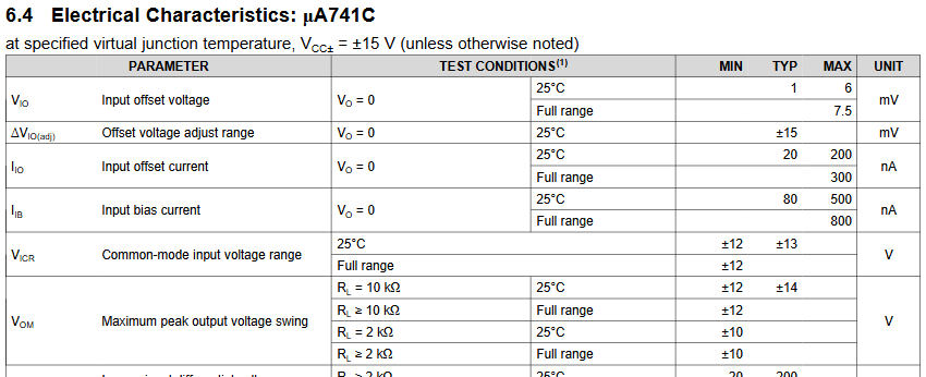
Ling L. wrote:
> Do you know what I might have done wrong?
You ignored the lines "Input Common Mode Voltage Range" and also "Output
Voltage Range" in the datasheet.

By reading them you can easily see, that 0.45V is much to low for a
negative supply voltage of 0V. There you must have at least 2V (in worst
case 3V). And it reaches up to 3V (in worst case 2V). So in worst case
according to the DS the usable input range with 5V unipolar supply is
nonexistent!

And also the output of this very, very ancient OP will never ever reach
0V or 5V. It will be able to swing from somewhat 2V (as you observed) to
somewhat 3V.

With other words: all of those old OP schematics only work with
+-12V..15V as supply for the OP. If you want to change that, you also
have to change the OP to a rail-to-rail (R2R) input and output OP.
:
Edited by Moderator
Please log in before posting. Registration is free and takes only a minute.
Existing account
Do you have a Google/GoogleMail account? No registration required!
Log in with Google account
Log in with Google account
No account? Register here.