1 | library ieee ; |
2 | |
3 | use ieee.std_logic_1164.all ; |
4 | use ieee.std_logic_arith.all; |
5 | use ieee.std_logic_unsigned.all; |
6 | |
7 | entity SevenSegmentDecoder is |
8 | port
|
9 | (
|
10 | ClockIn , -- General Clock |
11 | nResetIn -- Generar Reset |
12 | : in std_logic; |
13 | |
14 | NumberIn -- Number for display |
15 | : in std_logic_vector(3 downto 0); |
16 | nSegmentAOut, -- Segment A of 7 Segment Display A |
17 | nSegmentBOut, -- Segment B of 7 Segment Display F B |
18 | nSegmentCOut, -- Segment C of 7 Segment Display G |
19 | nSegmentDOut, -- Segment D of 7 Segment Display E C |
20 | nSegmentEOut, -- Segment E of 7 Segment Display D |
21 | nSegmentFOut, -- Segment F of 7 Segment Display |
22 | nSegmentGOut -- Segment G of 7 Segment Display |
23 | : out std_logic |
24 | );
|
25 | end SevenSegmentDecoder; |
26 | |
27 | architecture ArchSevenSegmentDecoder of SevenSegmentDecoder is |
28 | |
29 | begin
|
30 | DisplayDecoder_Process: |
31 | process (ClockIn) |
32 | begin
|
33 | if (ClockIn'event and ClockIn = '1') then |
34 | case nResetIn is |
35 | when '0' => |
36 | nSegmentAOut <= '1'; -- Segment A of 7 Segment Display A |
37 | nSegmentBOut <= '1'; -- Segment B of 7 Segment Display F B |
38 | nSegmentCOut <= '1'; -- Segment C of 7 Segment Display G |
39 | nSegmentDOut <= '1'; -- Segment D of 7 Segment Display E C |
40 | nSegmentEOut <= '1'; -- Segment E of 7 Segment Display D |
41 | nSegmentFOut <= '1'; -- Segment F of 7 Segment Display |
42 | nSegmentGOut <= '1'; -- Segment G of 7 Segment Display |
43 | when others => |
44 | case NumberIn is |
45 | when X"0" => |
46 | nSegmentAOut <= '0'; -- Segment A of 7 Segment Display A |
47 | nSegmentBOut <= '0'; -- Segment B of 7 Segment Display F B |
48 | nSegmentCOut <= '0'; -- Segment C of 7 Segment Display G |
49 | nSegmentDOut <= '0'; -- Segment D of 7 Segment Display E C |
50 | nSegmentEOut <= '0'; -- Segment E of 7 Segment Display D |
51 | nSegmentFOut <= '0'; -- Segment F of 7 Segment Display |
52 | nSegmentGOut <= '1'; -- Segment G of 7 Segment Display |
53 | when X"1" => |
54 | nSegmentAOut <= '1'; -- Segment A of 7 Segment Display A |
55 | nSegmentBOut <= '0'; -- Segment B of 7 Segment Display F B |
56 | nSegmentCOut <= '0'; -- Segment C of 7 Segment Display G |
57 | nSegmentDOut <= '1'; -- Segment D of 7 Segment Display E C |
58 | nSegmentEOut <= '1'; -- Segment E of 7 Segment Display D |
59 | nSegmentFOut <= '1'; -- Segment F of 7 Segment Display |
60 | nSegmentGOut <= '1'; -- Segment G of 7 Segment Display |
61 | when X"2" => |
62 | nSegmentAOut <= '0'; -- Segment A of 7 Segment Display A |
63 | nSegmentBOut <= '0'; -- Segment B of 7 Segment Display F B |
64 | nSegmentCOut <= '1'; -- Segment C of 7 Segment Display G |
65 | nSegmentDOut <= '0'; -- Segment D of 7 Segment Display E C |
66 | nSegmentEOut <= '0'; -- Segment E of 7 Segment Display D |
67 | nSegmentFOut <= '1'; -- Segment F of 7 Segment Display |
68 | nSegmentGOut <= '0'; -- Segment G of 7 Segment Display |
69 | when X"3" => |
70 | nSegmentAOut <= '0'; -- Segment A of 7 Segment Display A |
71 | nSegmentBOut <= '0'; -- Segment B of 7 Segment Display F B |
72 | nSegmentCOut <= '0'; -- Segment C of 7 Segment Display G |
73 | nSegmentDOut <= '0'; -- Segment D of 7 Segment Display E C |
74 | nSegmentEOut <= '1'; -- Segment E of 7 Segment Display D |
75 | nSegmentFOut <= '1'; -- Segment F of 7 Segment Display |
76 | nSegmentGOut <= '0'; -- Segment G of 7 Segment Display |
77 | when X"4" => |
78 | nSegmentAOut <= '1'; -- Segment A of 7 Segment Display A |
79 | nSegmentBOut <= '0'; -- Segment B of 7 Segment Display F B |
80 | nSegmentCOut <= '0'; -- Segment C of 7 Segment Display G |
81 | nSegmentDOut <= '1'; -- Segment D of 7 Segment Display E C |
82 | nSegmentEOut <= '1'; -- Segment E of 7 Segment Display D |
83 | nSegmentFOut <= '0'; -- Segment F of 7 Segment Display |
84 | nSegmentGOut <= '0'; -- Segment G of 7 Segment Display |
85 | when X"5" => |
86 | nSegmentAOut <= '0'; -- Segment A of 7 Segment Display A |
87 | nSegmentBOut <= '1'; -- Segment B of 7 Segment Display F B |
88 | nSegmentCOut <= '0'; -- Segment C of 7 Segment Display G |
89 | nSegmentDOut <= '0'; -- Segment D of 7 Segment Display E C |
90 | nSegmentEOut <= '1'; -- Segment E of 7 Segment Display D |
91 | nSegmentFOut <= '0'; -- Segment F of 7 Segment Display |
92 | nSegmentGOut <= '0'; -- Segment G of 7 Segment Display |
93 | when X"6" => |
94 | nSegmentAOut <= '0'; -- Segment A of 7 Segment Display A |
95 | nSegmentBOut <= '1'; -- Segment B of 7 Segment Display F B |
96 | nSegmentCOut <= '0'; -- Segment C of 7 Segment Display G |
97 | nSegmentDOut <= '0'; -- Segment D of 7 Segment Display E C |
98 | nSegmentEOut <= '0'; -- Segment E of 7 Segment Display D |
99 | nSegmentFOut <= '0'; -- Segment F of 7 Segment Display |
100 | nSegmentGOut <= '0'; -- Segment G of 7 Segment Display |
101 | when X"7" => |
102 | nSegmentAOut <= '0'; -- Segment A of 7 Segment Display A |
103 | nSegmentBOut <= '0'; -- Segment B of 7 Segment Display F B |
104 | nSegmentCOut <= '0'; -- Segment C of 7 Segment Display G |
105 | nSegmentDOut <= '1'; -- Segment D of 7 Segment Display E C |
106 | nSegmentEOut <= '1'; -- Segment E of 7 Segment Display D |
107 | nSegmentFOut <= '1'; -- Segment F of 7 Segment Display |
108 | nSegmentGOut <= '1'; -- Segment G of 7 Segment Display |
109 | when X"8" => |
110 | nSegmentAOut <= '0'; -- Segment A of 7 Segment Display A |
111 | nSegmentBOut <= '0'; -- Segment B of 7 Segment Display F B |
112 | nSegmentCOut <= '0'; -- Segment C of 7 Segment Display G |
113 | nSegmentDOut <= '0'; -- Segment D of 7 Segment Display E C |
114 | nSegmentEOut <= '0'; -- Segment E of 7 Segment Display D |
115 | nSegmentFOut <= '0'; -- Segment F of 7 Segment Display |
116 | nSegmentGOut <= '0'; -- Segment G of 7 Segment Display |
117 | when X"9" => |
118 | nSegmentAOut <= '0'; -- Segment A of 7 Segment Display A |
119 | nSegmentBOut <= '0'; -- Segment B of 7 Segment Display F B |
120 | nSegmentCOut <= '0'; -- Segment C of 7 Segment Display G |
121 | nSegmentDOut <= '0'; -- Segment D of 7 Segment Display E C |
122 | nSegmentEOut <= '1'; -- Segment E of 7 Segment Display D |
123 | nSegmentFOut <= '0'; -- Segment F of 7 Segment Display |
124 | nSegmentGOut <= '0'; -- Segment G of 7 Segment Display |
125 | when X"A" => |
126 | nSegmentAOut <= '0'; -- Segment A of 7 Segment Display A |
127 | nSegmentBOut <= '0'; -- Segment B of 7 Segment Display F B |
128 | nSegmentCOut <= '0'; -- Segment C of 7 Segment Display G |
129 | nSegmentDOut <= '1'; -- Segment D of 7 Segment Display E C |
130 | nSegmentEOut <= '0'; -- Segment E of 7 Segment Display D |
131 | nSegmentFOut <= '0'; -- Segment F of 7 Segment Display |
132 | nSegmentGOut <= '0'; -- Segment G of 7 Segment Display |
133 | when X"B" => |
134 | nSegmentAOut <= '1'; -- Segment A of 7 Segment Display A |
135 | nSegmentBOut <= '1'; -- Segment B of 7 Segment Display F B |
136 | nSegmentCOut <= '0'; -- Segment C of 7 Segment Display G |
137 | nSegmentDOut <= '0'; -- Segment D of 7 Segment Display E C |
138 | nSegmentEOut <= '0'; -- Segment E of 7 Segment Display D |
139 | nSegmentFOut <= '0'; -- Segment F of 7 Segment Display |
140 | nSegmentGOut <= '0'; -- Segment G of 7 Segment Display |
141 | when X"C" => |
142 | nSegmentAOut <= '0'; -- Segment A of 7 Segment Display A |
143 | nSegmentBOut <= '1'; -- Segment B of 7 Segment Display F B |
144 | nSegmentCOut <= '1'; -- Segment C of 7 Segment Display G |
145 | nSegmentDOut <= '0'; -- Segment D of 7 Segment Display E C |
146 | nSegmentEOut <= '0'; -- Segment E of 7 Segment Display D |
147 | nSegmentFOut <= '0'; -- Segment F of 7 Segment Display |
148 | nSegmentGOut <= '1'; -- Segment G of 7 Segment Display |
149 | when X"D" => |
150 | nSegmentAOut <= '1'; -- Segment A of 7 Segment Display A |
151 | nSegmentBOut <= '0'; -- Segment B of 7 Segment Display F B |
152 | nSegmentCOut <= '0'; -- Segment C of 7 Segment Display G |
153 | nSegmentDOut <= '0'; -- Segment D of 7 Segment Display E C |
154 | nSegmentEOut <= '0'; -- Segment E of 7 Segment Display D |
155 | nSegmentFOut <= '1'; -- Segment F of 7 Segment Display |
156 | nSegmentGOut <= '0'; -- Segment G of 7 Segment Display |
157 | when X"E" => |
158 | nSegmentAOut <= '0'; -- Segment A of 7 Segment Display A |
159 | nSegmentBOut <= '1'; -- Segment B of 7 Segment Display F B |
160 | nSegmentCOut <= '1'; -- Segment C of 7 Segment Display G |
161 | nSegmentDOut <= '0'; -- Segment D of 7 Segment Display E C |
162 | nSegmentEOut <= '0'; -- Segment E of 7 Segment Display D |
163 | nSegmentFOut <= '0'; -- Segment F of 7 Segment Display |
164 | nSegmentGOut <= '0'; -- Segment G of 7 Segment Display |
165 | when X"F" => |
166 | nSegmentAOut <= '0'; -- Segment A of 7 Segment Display A |
167 | nSegmentBOut <= '1'; -- Segment B of 7 Segment Display F B |
168 | nSegmentCOut <= '1'; -- Segment C of 7 Segment Display G |
169 | nSegmentDOut <= '1'; -- Segment D of 7 Segment Display E C |
170 | nSegmentEOut <= '0'; -- Segment E of 7 Segment Display D |
171 | nSegmentFOut <= '0'; -- Segment F of 7 Segment Display |
172 | nSegmentGOut <= '0'; -- Segment G of 7 Segment Display |
173 | when others => |
174 | nSegmentAOut <= '1'; -- Segment A of 7 Segment Display A |
175 | nSegmentBOut <= '1'; -- Segment B of 7 Segment Display F B |
176 | nSegmentCOut <= '1'; -- Segment C of 7 Segment Display G |
177 | nSegmentDOut <= '1'; -- Segment D of 7 Segment Display E C |
178 | nSegmentEOut <= '1'; -- Segment E of 7 Segment Display D |
179 | nSegmentFOut <= '1'; -- Segment F of 7 Segment Display |
180 | nSegmentGOut <= '1'; -- Segment G of 7 Segment Display |
181 | end case; |
182 | end case; |
183 | end if; |
184 | end process DisplayDecoder_Process; |
185 | |
186 | end ArchSevenSegmentDecoder; |
berndl wrote:
> that's the worst 7-segment decoder I've ever seen...

 You can put better and more simply for understand design.
It's not problem for me and other readers.

 It's place for discuss and looking for better way for design.

 Regards Alex.

 P.S.

 All readers are waiting to see your nice and simply for understand
design.
:
Edited by User
since you want to drive 4 7-segment displays, according to your I/O-list
1 | (NumberIn -- Number for display |
2 | : in std_logic_vector(3 downto 0); |
(but you didn't do this) and you allocate libraries which you are never
using
1 | use ieee.std_logic_arith.all; |
2 | use ieee.std_logic_unsigned.all; |
 and, of course, these are outdated libs...

and you are doing it the most inefficient, most complicate way, your
example is by far the worst 7-seg decoder I've ever seen...

You are flooding the forum here. What you show is not really something I
want to teach/tell people when they do logic-design...
Why is your decoder clocked? It doesn't need any saved state or
registers.
Andreas S. wrote:
> Why is your decoder clocked? It doesn't need any saved state or
> registers.

it simply doesn't matter. I just want to give out some information with
4 7-seg-displays. And clocking this will resolve any issue with
timing... I don't care about a delay of 10ns...
Andreas S. wrote:
> Why is your decoder clocked?
Don't throw bricks when you live in a glass house: why is yours?
> It doesn't need any saved state or registers.
Indeed.

Alexander S. wrote:
> It's place for discuss
What do you want to make better in your design?

> and looking for better way for design.
There is a stop watch with a 4 digit 7-segment display:
http://www.lothar-miller.de/s9y/archives/88-VHDL-vs.-Verilog-am-Beispiel-einer-Stoppuhr.html
That whole design consumes less space and is better readable than your
copyandpaste orgy.
Lothar M. wrote:
> Andreas S. wrote:
>> Why is your decoder clocked?
> Don't throw bricks when you live in a glass house: why is yours?

What are you talking about? I don't remember that I ever published a
seven segment decoder.
:
Edited by User
Andreas S. wrote:
> Lothar M. wrote:
>> Andreas S. wrote:
>>> Why is your decoder clocked?
>> Don't throw bricks when you live in a glass house: why is yours?
>
> What are you talking about? I don't remember that I ever published a
> seven segment decoder.

Andreas, I just wanted to ask your question... Seems that this thread is
a really dead one. We simply should talk about more interesting stuff in
other threads, like to read you again...
berndl wrote:
> Andreas, I just wanted to ask your question...
Deeply sorry, I muddled up the "Alexander S." with "Andreas S."

> We simply should talk about more interesting stuff in other threads
Indeed.
Andreas S. wrote:
> Why is your decoder clocked? It doesn't need any saved state or
> registers.

You are right :if your design only decoder you do not need
clock/register.

 But if your decoder small part of big high speed design, speed of your
decoder it's part speed of all design.

 Regards Alex.
Lothar M. wrote:

> What do you want to make better in your design?
>
 I want to know : are my designs correctly according to VHDL or may be
more optimally ... ready for high speed etc .
 Regards Alex.
Alexander S. wrote:
> But if your decoder small part of big high speed design, speed of your
> decoder it's part speed of all design.
And besides general statements: what's the use of (or the need for) a
clock at this very point? Why should it be necessary to update 7-segment
displays some 50000000 times a second? How fast is the led driver
circuit? And how fast are your eyes?
Attached files:
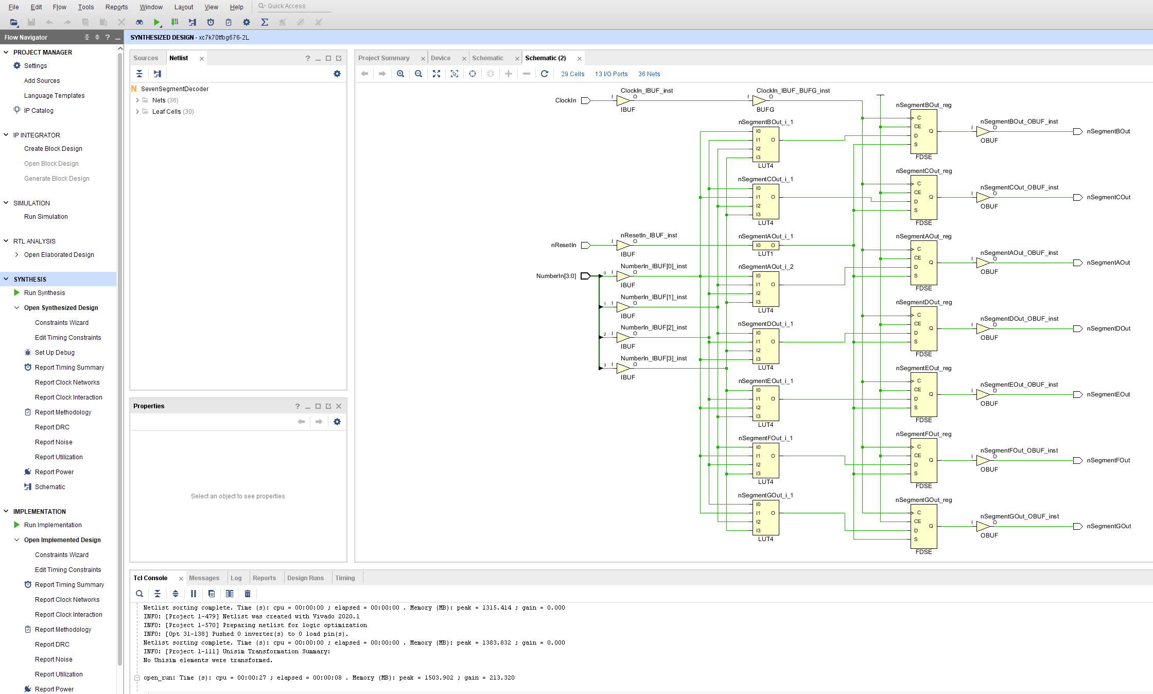
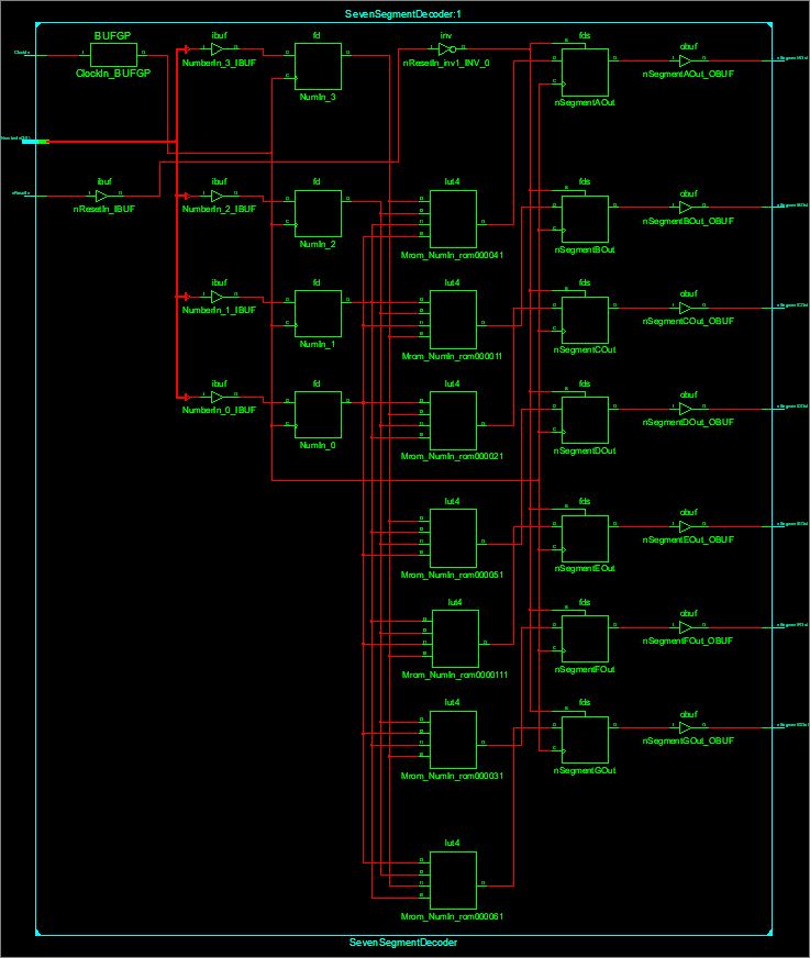
Lothar M. wrote:
.
> There is a stop watch with a 4 digit 7-segment display:
>
http://www.lothar-miller.de/s9y/archives/88-VHDL-vs.-Verilog-am-Beispiel-einer-Stoppuhr.html
> That whole design consumes less space and is better readable than your
> copyandpaste orgy.


 In the picture you can see schematic of implementation by Xilinx my
decoder design.

(Sorry for duplicate pictures. I can't not delete pictures. Can anybody
help me delete duplicate pictures ?)

 Your decoder design :
1 | -- the decoder
|
2 | segments <= "1000000" when digit=0 else |
3 | "1111001" when digit=1 else |
4 | "0100100" when digit=2 else |
5 | "0110000" when digit=3 else |
6 | "0011001" when digit=4 else |
7 | "0010010" when digit=5 else |
8 | "0000010" when digit=6 else |
9 | "1111000" when digit=7 else |
10 | "0000000" when digit=8 else |
11 | "0010000" when digit=9 else |
12 | "0111111"; -- is a dash, but will hopefully never be used! |
 Your design is same with my design.

You use :
1 | segments <= "1000000" when digit=0 else |
I use :
1 | case NumberIn is |
2 | when X"0" => |
3 | nSegmentAOut <= '0'; -- Segment A of 7 Segment Display A |
4 | nSegmentBOut <= '0'; -- Segment B of 7 Segment Display F B |
5 | nSegmentCOut <= '0'; -- Segment C of 7 Segment Display G |
6 | nSegmentDOut <= '0'; -- Segment D of 7 Segment Display E C |
7 | nSegmentEOut <= '0'; -- Segment E of 7 Segment Display D |
8 | nSegmentFOut <= '0'; -- Segment F of 7 Segment Display |
9 | nSegmentGOut <= '1'; -- Segment G of 7 Segment Display |
 Yes !

Your code is more shortly .

 But my code more easy for understand debug and repair.
My design is faster
(  Your design contains more than 10 consecutive checks, and mine always
does only one check.
 You do not know how the development system will make optimization and
what will be the result.),

 sometimes it's matters.
:
Edited by User
Lothar M. wrote:
> How fast is the led driver circuit?
> And how fast are your eyes?

 It's not problem of external device such as led driver or eyes or
other!

It's problem of big high speed (such as GMII 125 MHz of MII 25 ethernet
interfaces and other) design with display static information of main
design state.

  If you ask development system calculate max. design frequency of youe
design it calculated include your decoder as part of design.
 Development system don't know that decoder for static information.
 So, if your decoder can work with max. frequency such 10 MHz,
development system will say max. frequency of all design such 10 MHz.
---
 For calculate real time and  max. frequency of high speed part of your
design you have two option :

 All part of your design must work with max. frequency .

Or

 You need insert to development system constrains : not include slow
part of design to system timing calculation.

 If you have many slow parts in your design,
it's problem to insert this constrains.

 If you want to use your components in the future and don't know
application, preferable for my opinion to design all components for high
speed design : clockable.
 Don't use statement :
1 | if( = ) then |
2 | |
3 | elsif ( = ) then |
4 | |
5 | elsif ( = ) then |
6 | |
7 | else
|
8 | |
9 | end if; |
use only :
1 | case `SignalName` is |
2 | when `ConstantValue` => |
3 | -- Conditional Signal Assignment
|
4 | when `ConstantValue` => |
5 | -- Conditional Signal Assignment
|
6 | when `ConstantValue` => |
7 | -- Conditional Signal Assignment
|
8 | when others => |
9 | -- Conditional Signal Assignment
|
10 | end case; |
Use only synchronous reset .
....
....

 It's small part of many rules for high speed VHDL design.
.
:
Edited by User
Alexander S. wrote:
> Your code is more shortly .
>  But my code more easy for understand debug and repair.
> My design is faster (  Your design contains more than 10 consecutive
> checks, and mine always does only one check.
"My design is better than your design!"
Childisch game, isn't it?

> Your design contains more than 10 consecutive
> checks, and mine always does only one check.
Did you synthesize my design? Did you find 10 consecutive checks?

>  You do not know how the development system will make optimization and
> what will be the result.),
I check that out when my constraints are not met.

Alexander S. wrote:
> Don't use statement :
Why not? Can you proof your statements? What toolchain for what target
did you use for that proof?

> Use only synchronous reset .
My preffered design rule is: use no reset at all.
And if you have to use a reset, then ceck out whats the best way for the
target hardware. FPGAs behave different from manufacturer to
manufacturer and from series to another series.
Hi!

@Alexander S.
I just can't believe it...not a single knowledge how to develop VHDL
code, but such a big mouth!
First, I wanted to defend you against the arrogant tone in the forum,
but keep on reading your post I must see that you're unfortunately the
same ...


@Lothar don't waste your time with such kind of people and continue to
support people who are worth it.

Cheers :)
Attached files:
Lothar M. wrote:

> Did you synthesize my design? Did you find 10 consecutive checks?

  Yes.
Sorry ,it's only 9 consecutive checks in your design for decimal
display.

 In the Hex display such as in my design you will have 15 consecutive
checks.

 Regards Alex.
Attached files:
-

Lothar_M_Debounce.PNG
47 KB
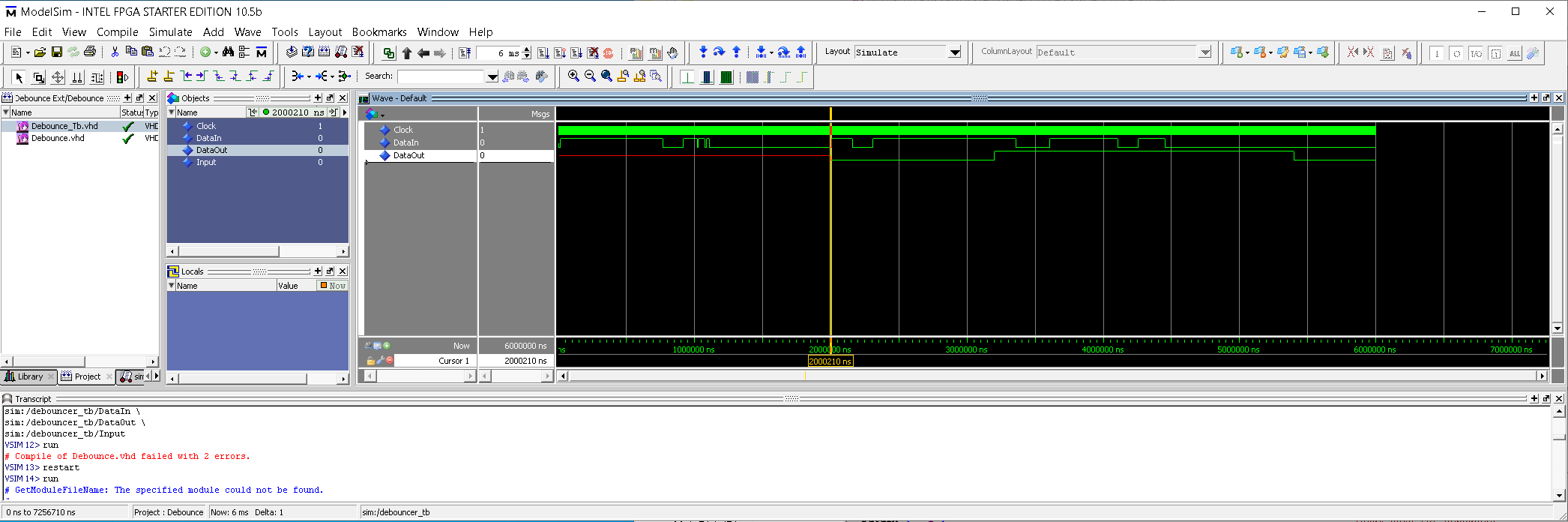
Lothar M. wrote:

> My preffered design rule is: use no reset at all.

 It's great rule : your designs have undefined state after power up.


See (attached picture) simulation of your reference Debounce design : it
may have 2 mS undefined output.

 If anybody include this design in the his design that all design will
have 2 mS undefined state after power up.

 Regards Alex.
:
Edited by User
Lothar M. wrote:
> Alexander S. wrote:

>> My design is faster (  Your design contains more than 10 consecutive
>> checks, and mine always does only one check.
> "My design is better than your design!"
> Childisch game, isn't it?

 Faster design it not say better if you do not need speed.
If you need speed your design may be not work.

 Regards Alex.
Attached files:
-

sseg_l.PNG
13 KB -

sseg_a.PNG
14 KB
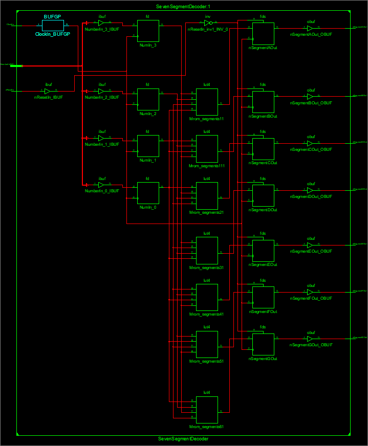
Alexander S. wrote:
> Yes. Sorry ,it's only 9 consecutive checks in your design for decimal
> display.
What is the resource use of those both designs? What is the timing
closure of both designs?

I did some tests with Xilinx ISE 14.7 (it's the only toolchain available
on this computer). I added input flipflops to get a timing calculation
to your design and implemented my design with the missing 7 segment
decoding for A to F. Now both of the designs do the very same.

Then I started the synthesizer and the result with your code is:
1 | Selected Device : 3s50pq208-5 |
2 | |
3 | Number of Slices: 6 out of 768 0% |
4 | Number of Slice Flip Flops: 11 out of 1536 0% |
5 | Number of 4 input LUTs: 8 out of 1536 0% |
6 | Number of IOs: 13 |
7 | Number of bonded IOBs: 13 out of 124 10% |
8 | Number of GCLKs: 1 out of 8 12% |
9 | : |
10 | Clock period: 2.482ns (frequency: 402.885MHz) |
The synthesis result with my code is:
1 | Selected Device : 3s50pq208-5 |
2 | |
3 | Number of Slices: 6 out of 768 0% |
4 | Number of Slice Flip Flops: 11 out of 1536 0% |
5 | Number of 4 input LUTs: 8 out of 1536 0% |
6 | Number of IOs: 13 |
7 | Number of bonded IOBs: 13 out of 124 10% |
8 | Number of GCLKs: 1 out of 8 12% |
9 | : |
10 | Clock period: 2.482ns (frequency: 402.885MHz) |
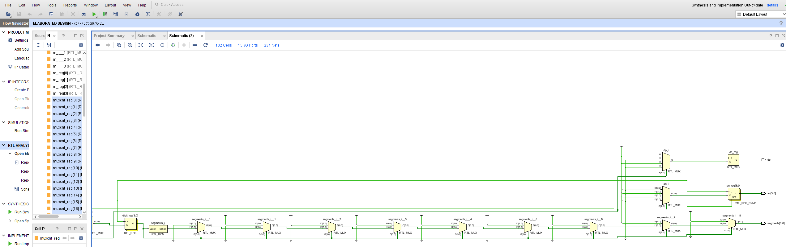
Do you find a difference?
Also the technology schematic of both look exactly the same.
And the RTL-schematic of both descriptions is much more simple:
input --> FF --> ROM(16x7) --> FF --> output

So even the old fashioned ISE toolchain can recognize such a simple
"everyday" description and transfer it correctly to a minimal
implementation.

Conclusion: neither of both ways is "faster" or "slower" in real life.

Alexander S. wrote:
> Lothar M. wrote:
>> My preffered design rule is: use no reset at all.
>  It's great rule : your designs have undefined state after power up.
SRAM based FPGAs have a well defined state at power up, because all of
the FPGA is loaded with defined values out of the config ROM in the
configuration cycle.
See the design guide of the configuration process for a specific FPGA
type. And for a Xilinx FPGA additionaly read the WP272.
:
Edited by Moderator
Lothar M. wrote:

> SRAM based FPGAs have a well defined state at power up, because all of
> the FPGA is loaded with defined values out of the config ROM in the
> configuration cycle.
> See the design guide of the configuration process for a specific FPGA
> type. And for a Xilinx FPGA additionaly read the WP272.

 But you do not know : how start your design with this defined state and
can't see that on the functional simulation !!!

 Regards Alex.
Lothar M. wrote:
> Do you find a difference?


 You see no difference for small design and after optimisation by
development tools.

 This optimisation not guaranteed by development tools.

My design will have this paramrters in all big design, Part of which is.

Your design will have parameters according to big design,Part of which
is and can change it if this big design will change.

 Regards Alex.

P.S.

 All asynchronous design can change it timing (without changes code)
after next implementation and will be or more good or more bad.
Have you already met Josef G. (bome) in this forum? I think you can
become best friends. He ist working on his own softcore processor called
bo8h:

https://www.mikrocontroller.net/articles/8bit-Computer:_bo8h
Andreas S. wrote:
> He ist working on his own softcore processor called  bo8h:

 With his VHDL design rules, this processor will not be quickly. I'm
sorry.

 Regards Alex.
Attached files:
-

Vivado_7_segments.PNG
230 KB

Lothar M. wrote:
 I started the synthesizer and the result with your code is:
> [pre]
> Selected Device : 3s50pq208-5
>
>  Number of Slices:                        6  out of    768     0%
>  Number of Slice Flip Flops:             11  out of   1536     0%
>  Number of 4 input LUTs:                  8  out of   1536     0%
>  Number of IOs:                          13
>  Number of bonded IOBs:                  13  out of    124    10%
>  Number of GCLKs:                         1  out of      8    12%


   See in the piture in the bottom : my design is smaller and not same
as your.

 It's only 7 (not 11) Slice Registers and we see that in the picture.

 Regards Alex.
:
Edited by User
Alexander S. wrote:
>  It's only 7 (not 11) Slice Registers
Fairly easy to see: because you kicked off the 4 input registers you can
easy calculate 11-4 = 7. Whats the news?

> my design is smaller and not same as your.
But in a usual design this decoder would use no (zero, nada, null, 0)
register at all. Because there is no need for no clock at all. And "no
clock" leads to "no registers".

> my design is smaller and not same as your.
This ist childisch.
Alexander, see it that way: when you are the big boss and your design
rules and your design style are the best in the world, why do you have
to prove it?
:
Edited by Moderator
Alexander S. wrote:
> Andreas S. wrote:
>> He ist working on his own softcore processor called  bo8h:
>
>  With his VHDL design rules, this processor will not be quickly. I'm
> sorry.

But you can try to persuade him that your style is much better.
Lothar M. wrote:
> you kicked off the 4 input registers you can
> easy calculate 11-4 = 7.

 My design never had input registers.Whats the news?
Regards Alex.
Lothar M. wrote:
> your design
> rules and your design style are the best in the world, why do you have
> to prove it?

 My design rules and my design style isn't the best in the world.
Your design rules and your design style is your problems

 Good luck in your designs.

 Regards Alex.
Alexander S. wrote:
> Your design rules and your design style is your problems
No. Lothars design rules are the result of experience and proven in real
hardware. Lothar can give reasons for every piece of code. And Lothar is
sharing a lot of his knowledge.

I have make often the same experience in FPGA design, so I can rate this
a little bit.


Duke
Alexander S. wrote:
> My design rules and my design style isn't the best in the world.
> Your design rules and your design style is your problems
>
>  Good luck in your designs.
>
>  Regards Alex.
Donald, is it you?
Duke Scarring wrote:

> I have make often the same experience in FPGA design, so I can rate this
> a little bit.
>
>
> Duke

   So, your experience say : asynchronous design more good (for high
speed design) then synchronous and that FPGA system does not need system
reset after Power Up ?

 I'm sorry that students have teachers like you.

 Regards Alex.
:
Edited by User
Alexander S. wrote:
> asynchronous design more good (for high
> speed design)

Who sad that? A rule of thumb: keep away from async stuff. It needs
different design rules (for the engineer) and the toolchains may not
protect you from mistakes.

Alexander S. wrote:
> FPGA system does not need system
> reset after Power Up

That's right. The FPGA does not needed an explicit reset, since due to
configuration, the FPGA is well defined. But: your design may need a
reset. See WP272 from Xilinx.

For me, I almost never have a POR. I use local resets when needed ans
where needed (stream interruptions, etc.). For example, I rarely reset
data register, most of the time, I only (re-)set (flow-) control
registers.

greetings
Alexander S. wrote:
> So, your experience say : asynchronous design more good (for high speed
> design) then synchronous
Where did you dig out this statement?

> and that FPGA system does not need system reset after Power Up ?
Yes. Indeed all SRAM based FPGA do not need a reset path in the VHDL
code. They will power up with predictable values.

> I'm sorry that students have teachers like you.
Alexander, no personal attack here, pls!
Lothar M. wrote:

> Yes. Indeed all SRAM based FPGA do not need a reset path in the VHDL
> code. They will power up with predictable values.

 Do you know from what state start your state machine if you have not
system reset ?

 Regards Alex.
Lothar M. wrote:
> Alexander S. wrote:
>> So, your experience say : asynchronous design more good (for high speed
>> design) then synchronous


> Where did you dig out this statement?

 Because you ask : why I use only synchronous logic !

 Regards Alex.
Alexander S. wrote:
>  Do you know from what state start your state machine if you have not
> system reset ?

During initialization of the FPGA "everything" is loaded from the
bitstream. This also includes the initialization values for all
registers. So the FPGA "knows" the states of all FSM.

Lothar wrote "predictable values" which means reproducible and well
defined. Of course it doesn't mean that the developer knows these
values. If one doesn't want to rely on the default values which are
determined by the VHDL used he can use explicit initialization values
for register definitions.
Alexander S. wrote:
> Do you know from what state start your state machine if you have not
> system reset ?
Yes. It behaves as for VHDL defined: the initial value is the leftmost
state in the state definitions. And for most synthesizers you can define
another initial value also. The synthesizers users guide is the place to
look for such information.

Alexander S. wrote:
> Because you ask : why I use only synchronous logic !
Where did I?
I'd asked why you implement unnecessary flipflops and add latency.
:
Edited by Moderator
Lothar M. wrote:
> Alexander S. wrote:

>> Because you ask : why I use only synchronous logic !
> Where did I?


> I'd asked why you implement unnecessary flipflops and add latency.

 This means the question : why I use only synchronous logic by setting
Flip Flop after LUT in common CELL!

 Regards Alex.
Andreas S. wrote:
> Of course it doesn't mean that the developer knows these
> values.

 So , you don't know from what state start your state machine ?

 Regards Alex.
:
Edited by User
Alexander S. wrote:
> Andreas S. wrote:
>> Of course it doesn't mean that the developer knows these
>> values.
>
>  So , you don't know from what state start your state machine ?

The FPGA doesn't know what the developer knows. It can only translate
the source code.
Alexander S. wrote:
> So , you don't know from what state start your state machine ?
As I said several times: RTFM of your toolchain. There it is written on
page 202!
https://www.xilinx.com/support/documentation/sw_manuals/xilinx2019_2/ug901-vivado-synthesis.pdf

And if you don't want to READ THE FULL MANUAL then learn searching the
internet:
https://www.xilinx.com/support/documentation/sw_manuals/help/iseguide/mergedProjects/destech/html/cd_webpackcontrolling_register_initial_states.html
Please log in before posting. Registration is free and takes only a minute.
Existing account
Do you have a Google/GoogleMail account? No registration required!
Log in with Google account
Log in with Google account
No account? Register here.