How to use FPGA to drive TFT LCD?
Which TFT?
TFT directly or TFT with controller?
Which FPGA?
What do you want to achieve, what's the surrounding project, ...?

br,mf
Cliff W. wrote:
> How to use FPGA to drive TFT LCD?


Just generate the correct timings, similar to VGA or HDMI.
https://www.fpga4fun.com/HDMI.html

For details plz consult 'your' TFT panel datasheet.
I have two TFT LCDs, one screen from Adafruit and one from Stone. I want
to implement the most basic functions, initialize the LCD, display RGB
colors and display pictures.
I am uploading the data sheet as an attachment.
So you have two displays with completely different control logic. The
first one is only a display for which you would have to implement the
basic control logic inside the FPGA. The second one is basically a
display already connected to a microcontroller where you can load
images, buttons, etc via an external software an then only need some
basic commands via a serial interface to draw on the display.
Cliff W. wrote:
> I want to implement the most basic functions, initialize the LCD,
> display RGB colors and display pictures.
... and play films in 4K.

> I have two TFT LCDs ...
> I want to implement the most basic functions
On both of them? Or only on the "easier" one? If that, then I would
recommend the YX700WV03, because you simply must connect some wires and
generate the fairly easy timing from page 7..9 of the data sheet.

The second ist not "a display", but instead a complete SOM connected to
the display. Theres no need for a FPGA to solve the tasks.
:
Edited by Moderator
Chris K. wrote:
> So you have two displays with completely different control logic.
> The
> first one is only a display for which you would have to implement the
> basic control logic inside the FPGA. The second one is basically a
> display already connected to a microcontroller where you can load
> images, buttons, etc via an external software an then only need some
> basic commands via a serial interface to draw on the display.

Okay, I will use the first TFT LCD.
>> I have two TFT LCDs ...
>> I want to implement the most basic functions
> On both of them? Or only on the "easier" one? If that, then I would
> recommend the YX700WV03, because you simply must connect some wires and
> generate the fairly easy timing from page 7..9 of the data sheet.

I think you are right, I will be using the first TFT LCD.
Lothar M. wrote:
>> I have two TFT LCDs ...
>> I want to implement the most basic functions
> On both of them? Or only on the "easier" one? If that, then I would
> recommend the YX700WV03, because you simply must connect some wires and
> generate the fairly easy timing from page 7..9 of the data sheet.

You also need a rather fast RAM for your project, which holds the data
for each pixel.

Because the actual display is a 18..24 bit type, you would need to
decide, if you want to reserve 16 or 32 bit of RAM for a pixel.

My recommendation is 16 bit: 5 bit for red and blue, each, and 6 bit for
green. This is the usual 565 format (I do know from Windows CE).

The actual problem ist the access by your microcontroller: µC-FPGA-RAM.
This needs to be transparent to the access RAM-FPGA-TFT. Keep in mind,
that the pixel clock will be around 30..40 MHz, so you will need to
establish 2 different accesses in your FPGA, each in a 15..20 ns
timeslot.

Because the TO asked such questions, I think, it would be better to use
a µC with a builtin TFT-peripheral, working by DMA on a external SDRAM.
There are useful chips in the market: LPC4088, some LPC17xx and similar.

W.S.
This sounds very professional, I'll take your advice and start learning
more about FPGAs! Thank you very much.
Attached files:
-

20210731_214946.jpg
240 KB
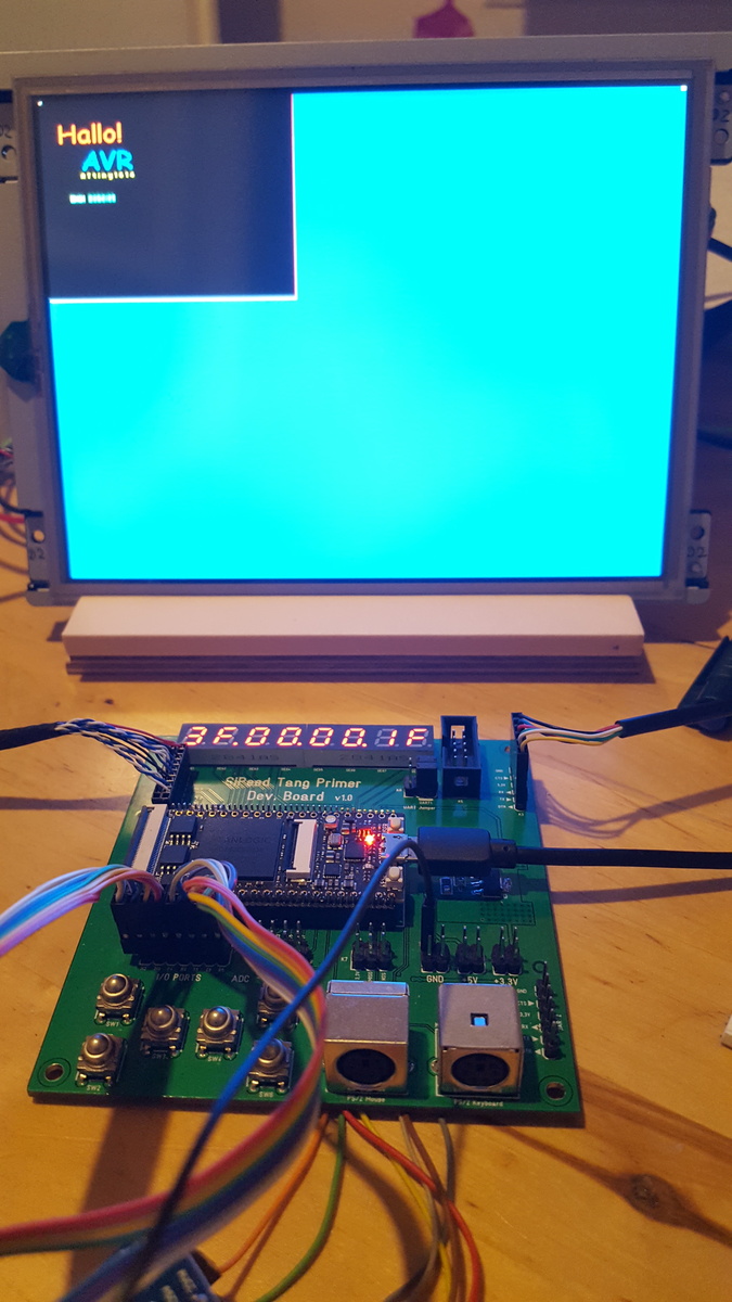
I am currently in the process of writing a small LCD / TFT controller
with SDRAM for data storage.  So far I have implemented the whole thing
in Verilog.  The advantage at the moment is the FPGA used.  This has
integrated the 64Mbit SDRAM.

Read pixel data: SDRAM -> RD-FiFo -> Display
Write pixel data: 6800 Interface -> WR-FiFo -> SDRAM

I was able to modify an SDRAM controller in such a way that I can
generate a continuous (burst) data stream reading beyond the page limit.
Since the data is stored in the SDRAM with a data width of 32 bits - but
I only need 16 bits for the display - I also have double the data rate
when reading.

This leaves enough time for data from an interface - I first integrated
an 8-bit parallel MCU 6800 interface to an AVR 8bit MCU like ATtiny1614.

My display have 800x600 pixel and use 1channel LVDS as interface. But
internaly FPGA I work with 40Mhz pixel clock.
Please log in before posting. Registration is free and takes only a minute.
Existing account
Do you have a Google/GoogleMail account? No registration required!
Log in with Google account
Log in with Google account
No account? Register here.