Hi,
I need to generate pulses at specific points in time and the pulses
should be periodical.

I need an counter.
I need comperators.
At every posedge of my clock signal, the counter is advanced by one and
when it reaches its end it start over at zero again ==> periodical.
There is one comperator for each pulse I need. The counter value is
compared at the negedge for equality , so this is save to not get false
results during the counting action.

The values identifying the points in time coming from outside and so
there is a special point in time (near the end of an cycle) to write
them into registers to have stable values for the next periode. No value
used for a comparison is grater than this point in time value ==> we
have a dead band.

I only give a sketch of code here to keep thins simple:

.....
// register
reg [10:0]  time_base_reg  = 11'd0;
reg [13:0]  signal_reg  = 14'd0;
... After signal pre-processing the remaining value is 11 bit wide.

...
always @(posedge clk)
   begin
     time_base_reg <= (enable) ? time_base_reg + 1 : 0;
   end

.....
always @(negedge clk)
  begin
    if ( time_base_reg == 11'd2043 )
      begin
  signal_reg <= signal;
        .. some more such lines ...
      end
    ... one version ..
    if ( time_base_reg < 11'd2043 )
  begin
    s1_r_reg <= ( time_base_reg == 11'd0 ) ? 1'd1 : 1'd0;
    s1_s_reg <= ( time_base_reg == p2_start + delay_reg ) ? 1'd1 : 1'd0;
        end
  end

Other version was, to isolate the s1_x_reg lines into separate always
blocks which also triggers at negedge of clk.

Now the 'fun':

Simulation works out anyway.

But using the real FPGA (Cyclon 10) some pulse trains working, and some
not. Sometimes no pulse is generated, sometimes there were randomly
missing pulses.

I tried a lot combinations, no idea whats going wrong.

Speed:
As an old hardware engineer I first draw schematics, placing comperators
and a counter and .. works fine, not one error. But, there is no
(simple) chance to have a parameter to set the width of the counter, the
registers ...

So I tried to put together a verilog version in the first step and
introduce parameters in the second step.

The first step fails.

Funny detail:
When I use a line like this:
always @(negedge clk)
  begin
    p2_h_r_reg   <= ( time_base_reg == p2_start ) ?  1 : 0;
  end
Here I get missing pulses.
But when I add (or subtract) something (value doesnt matter) it worked
out:

always @(negedge clk)
  begin
    p2_h_r_reg <= ( time_base_reg == p2_start+1 ) ?  1 : 0;
  end

Whats wrong with my design. I just tried to do the same as I do in my
symbolic schematic, just in 'code'. Schematic is fine ==> shouldn't be a
speed problem, principially.

(I am an software engineer too, maybe I use Verilog the wrong way??).

Thanks for helping

With best regards
Gerhard
Gerhard K. wrote:
> Whats wrong with my design.
I didn't see any input synchronizer.
Try http://www.lothar-miller.de/s9y/categories/35-Einsynchronisieren
with a translator.

Duke
Hi Duke,
the values specifying the trigger points were calculated within the same
fpga using the same clk signal.

At the rising edge of the 11th bit of the time_base the calculation is
triggered and when the time_base reaches 2043 the calculated value is
stored in the signal_reg at the negedge:

module pulses(  input clk,
    input [13:0] signal, .....

...

always @(negedge clk)
   begin
      if ( time_base_reg == 11'd2043 )
  begin
     signal_reg    <= signal;
....

As far as I understand Verilog (and this is not that far for now):

The input 'signal' is stored in the register 'signal_reg' if the
time_base_reg contains 11'd2043 and a falling edge at clk is detected.

The time_base_reg is incremented at rising edges of clk, so no
intermediate patterns on the time_base_reg outputs can cause an update
of 'signal_reg'.

The calculation of the value for 'signal' is triggered when the
time_base_reg is incremented from 1023 to 1024 which causes the 11th bit
to change from 0 to 1 ==> rising edge. This rising edge triggers the
signal generator.

I use this mechanism in my schematic I put together using symbols and
connections like classic schematics of logic circuits. This works fine,
no errors at all.

Doing the same in Verilog ...

So, why should I use special synchronizers in Verilog, the classic
schematics definetely didn't need them.

Is Verilog that different?

With best regards

Gerhard
Gerhard56 wrote:
> So, why should I use special synchronizers in Verilog, the classic
> schematics definetely didn't need them.
>
> Is Verilog that different?

For external asynchrosnous signals in a clocked circuit I use always two
flip-flops to synchronize the signal. If you don't do this, and you use
the signal at different destinations in your design, then the
destinations can an will see different levels of your signal at the same
time, because of different routing length.

That is no question of Verilog or VHDL or schematic.

Gerhard K. wrote:
> The values identifying the points in time coming from outside
That's sounds like an external signal.
Can you make sure they didn't get an update when your internal counter
does the overflow?

Gerhard56 wrote:
> the values specifying the trigger points were calculated within the same
> fpga using the same clk signal.
That's sounds like an internal signal.

Duke
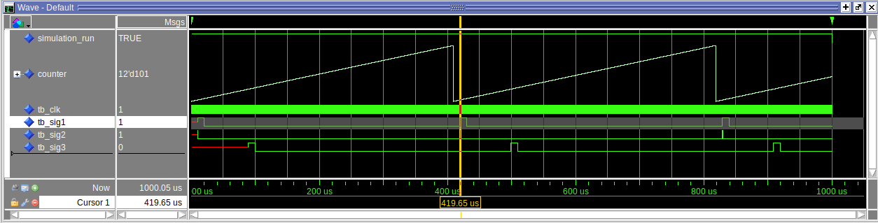
Hi Duke,

the 'signal' is generated on the same fpga using the same clk, generated
by the same PLL.
'Outside' means: outside of the module, not outside of this fpga.

I know, I have to synchronize everything from outside the fpga, but
there isn#t anything ...

The signal generator is triggered at rising edge of the 11th bit of my
time_base, so this is at time_base = 1024. There were 2043 - 1024
clk-cycles left to get signal ready. It needs maybe 3 or 4 cycles.

This concept works with 'classical schematic input', which is internally
converted to Verilog or VHDL by Quartus system.

==> I am pretty sure, that signal is stable when time_base reaches 2043.

After that moment, I only use 'signal_reg' ==> this should be stable for
all values of 'time_base_reg' except 2043.

I tried to enable comparison only at 'time_base_reg' < 2043, so I am
pretty sure, that the values I use for comparison didn't change during
'time_base_reg' runs up from 0 to 2022.

Maybe you (or some one else) can sketch some code, how to generate a
time_base (counter) counting up periodically and how to compare some
values against this time_base to get out short pulses (one clk cycle) if
the value matches.

Maybe I have to use a 'case' instead of 'if', no idea.

I thought this is a simple task written in Verilog giving an elegant and
easy to understand code, but ... works only in simulator, not in the
real world.

With best regards

Gerhard
Attached files:
-

simulation.png
22 KB
Ok, than I didn't understand you correctly.
In synchronous designs the FPGA tools make sure that your signals are
stable at the next edge of clock. (If you set the constraints
correctly.)

I'm not a native verilog speaker, so I can show you a possible solution
only in VHDL.

Duke
Gerhard K. wrote:
> But using the real FPGA (Cyclon 10) some pulse trains working, and some
> not. Sometimes no pulse is generated, sometimes there were randomly
> missing pulses.
> I tried a lot combinations, no idea whats going wrong.

are you sure that you're not hunting a measurement artefact? are only
short pulses missing or does it also affect longer pulses? is the
sampling rate of your oscilloscope appropriate for the puls duration?
Hi Achim,

the clock is 400Mhz, the pulse-length is 2.5ns.
The scope is a Keysight 500Mhz scope, with 2 GSa/s.

When I use my 'symbolic input' solution no pulse is missing, when I use
the Verilog version (same fpga, scope ...) pulses were missing.

This short pulses were used to set/reset flip.flops which were inside
the same fpga, so I only see pulses of ~200kHz outside the fpga.

In my 'symbolic input' version, the short pulses inside the fpga were
able to set/reset the flip-flops, and yes, the clock for the FFs is
correct, so the rising edge is perfect in the middle of the short
pulses. I checked this per simulation for both solutions.

The Verilog version should do the same thing (but give the chance to use
parameters) but for some reason .. no chance.

With best regards

Gerhard
Gerhard56 wrote:
> the clock is 400Mhz
That sounds quite fast for a low cost device.
Did you set a timing constraint for your clock?
What results give the timing report?
Duke Scarring wrote:
> Gerhard56 wrote:
>> the clock is 400Mhz
> That sounds quite fast for a low cost device.
> Did you set a timing constraint for your clock?
> What results give the timing report?

Especially as you use posedge and negedge...then you have critical paths
of 800 MHz.

Gerhard K. wrote:
> The counter value is
> compared at the negedge for equality , so this is save to not get false
> results during the counting action.

You dont need to take care of this in a constrained synchronous design.
Just write and read your counter on posedge.
Duke Scarring wrote:
> That sounds quite fast for a low cost device.
And additionally the clock frequency ist virtually doubled by using both
edges.

And not only this. Because if the clock signal is misshaped lets say
30/70 instead of 50/50 then there is less time to stabilize internal
signals for a proper setup time.

Gerhard56 wrote:
> the clock is 400Mhz, the pulse-length is 2.5ns
Although this looks like a fairly low number to one used to processors
with up to and over 2 GHz, it is a very demanding task for a FPGA
design.

I would slow down the clock to reasonable 100 MHz and check the
behaviuor again. And I would use only 1 and the same clock edge
throughout the whole design.
Hi,

as I told you, no speed problems with 'symbolic input'.
Clock is 50/50, Intel told me in the PLL specs and basic clock is 50/50
really good, my scope told me. But you were right, I have to double
check everything.

BUT, I got it ...

I checked out your VHDL code and you increment the counter at the LAST
line of the process/block. I do it at the first line.

Ok, I also used a different clock edge, but who knows ..

I did the comparisons now in the posedge block and at the last line of
this block I increment the counter ==> works fine.

Thanks a lot.

As I guessed at the beginning, as (an also) software-engeneer, I look at
code lines different, which isn't that helpful looking at Verilog/VHDL
code.

Thanks for helping.

With best regards

Gerhard
Gerhard56 wrote:
> I checked out your VHDL code and you increment the counter at the LAST
> line of the process/block. I do it at the first line.
If I use a signal in VHDL process block, it is no difference, where the
line stands. The counter value is (logically) updated at the end of the
process and the last assignment 'win'.

I do the counter update in the last line, to make clear that the
compares are done with the 'old' value.

But the concept with blocking and always in verilog may be different.

Duke
Today I could test to synthesize the VHDL code from above.
I use a Lattice MachXO2-2000, which I think is somewhat similar to
Cyclone 10.

The maximum usable frequency is 150 MHz:
1 | Report: 150.150MHz is the maximum frequency for this preference. |
2 | |
3 | Report Summary |
4 | -------------- |
5 | ---------------------------------------------------------------------------- |
6 | Preference | Constraint| Actual|Levels |
7 | ---------------------------------------------------------------------------- |
8 | | | | |
9 | FREQUENCY PORT "clk" 150.000000 MHz ; | 150.000 MHz| 150.150 MHz| 0 |
10 | | | | |
11 | ---------------------------------------------------------------------------- |
12 | |
13 | |
14 | All preferences were met. |
Duke
Please log in before posting. Registration is free and takes only a minute.
Existing account
Do you have a Google/GoogleMail account? No registration required!
Log in with Google account
Log in with Google account
No account? Register here.