-
PDF
LQ121S1LG75.pdf
L(GND) or Open Controller THC63LVDM83R RXIN0+ Single LVDS interface contained in a control IC R0-R5,G0 7 TA 0 - 6 RA 0 - 6 7 S RXIN0- T RB 0 - 6 G1-G5,B0,B1 TB 0 - 6 V T 7 TC 0 - 6 - RXIN1+ E RC 0 - 6 B2-B5, NA,NA,DE 7 O RXIN1- L TD 0 - 6 - A RD 0 - 6 t R6,R7,G6,G7, E RXIN2+ A u L - i A RXIN2- O c
in „Mini2440 LVDS Display Adapter für größere TFTs“ · Projekte & Code ·
-
PDF
HV-Progger.pdf
(OC0A)PB2 13 SDI 0 R 1 4 R R TARGET (AIN1)PB1 12 RESET D2 8 1 4 (AIN0)PB0 VCC_P E E VCC NRES/PB5 3 PA1(XTAL2) - 1 1 PB4 2 5 PA0(XTAL1) O 1 GND E PB2 7 (ICP)PD6 11 R 0 L PB1 6 (T1)PD5 9 P 5 5 R 6 4 GND PB0 5 5 (T0)PD4 8 + 0 R + 20 VCC (INT1)PD3 7 T2 GND 2 ATTINY45-20P (INT0)PD2 6 BC554 0 GND (TXD
in „Einfacher Serial-HV-Fuse-Progger für AVR“ · Projekte & Code ·
-
Datei
Profibus_DP_slave_mega.ino
define BAUD 45450 // DELAY_TBIT = 44 // Working on Arduino @16MHz //#define trimmer A0 //#define led 5 //#define servo 10 #define piu A14 #define meno A15 #define jolly A12 #define rs 12 #define en1 11 #define d4 4 #define d5 5 #define d6 6 #define d7 7 #define en2 10 //----------ingressi---------- byte
-
Datei
DCF77.INC
flags, dcf77value add r0, a0 st z, r0 _ddc5: cbr flags, 1<<dcf77pulse^1<<dcf77value inc newsecond brne _ddc6 sbr flags, 1<<dcf77error _ddc6: ret ;------------------------------------------------------------------------- Dcf77Table: .db AddrNewMinute
-
Datei
irmp.c-patch1.patch
diff --git "a/irmp.c" "b/irmp.c" index 0427770..bbaca5a 100644 --- "a/irmp.c" +++ "b/irmp.c" @@ -2978,6 +2978,12 @@ irmp_store_bit2 (uint_fast8_t value) } #endif // IRMP_SUPPORT_RC5_PROTOCOL == 1 && (IRMP_SUPPORT_FDC_PROTOCOL == 1 || IRMP_SUPPORT_RCCAR_PROTOCOL
in „IRMP - Infrared Multi Protocol Decoder“ · Projekte & Code ·
-
PDF
Medugu_et_al.pdf
day open – sky test giving irradiances of 20.76 and 21.7 Wm for RMP001 and CMP3, respectively, at 5:25 p.m. RMP001 will be used for the collection of authentic irradiance data for comparative evaluation with the theoretical predicted results given by researchers. Key words: Solar radiation, pyranometer
in „Sonnenscheindauer Sensor selber bauen Eigenbau ATmega Assembler“ · Projekte & Code ·
-
PDF
Transistortester092k.pdf
2150nF 2% 2149nF 2% 22µF 21,94µF 25,61µF 16% 21,92µF 0% 21,41µF 3% 21,41µF 3% 16% 0% 1% 1% 47µF 47,5µF 55,29µF 47,30µF 46,70µF 46,9µF 100µF 97,5µF 112,94µF 15% 91,30µF 6% 91,7µF 6% 91,3µF 6% 220µF 229µF 272,69µF 19% 219,2µF 5% 219,2µF 5% 219,2µF 5% 28% 0% 1% 1% 1000µF 1071µF 1371,95µF 1076µF 1063µF
-
PDF
USI_Servo_readme.pdf
zwischen 0.9ms und 2.1ms, bei 1.5ms nimmt der Servo theoretisch die Mittelposition ein. Für die Neutralposition bei 1.5ms ist ein Wert von 1500us / 8us = 187 ins Compare-Register zu schreiben. In der Praxis verhalten sich die Servos
in „Ansteuerung von Modellbauservos via TWI mit ATTiny25 in C“ · Projekte & Code ·
-
Thread
Software MP3 decoder for ATmega/ATxmega
embdev.net/topic/370373) I've implemented the remaining features to fully *) decode single channel MPEG 2.5 Layer 3/LSF. Beside that a few nasty bugs were fixed (but don't worry, there are still some left for everybody). You can feed any single channel MP3 file with sampling frequency 8, 11.025 or 12 kHz
headphones have to be connected to pins OC1A (direct output) and OC1B (inverted output) via simple RC low pass filter. Try 47 Ohms and 2.2 or 4.7 uF. For suppression of DC connect a 100 uF capacitor in series. Of course, this is just the simplest design. Higher order low pass filters will provide better
Projekte & Code ·Horst Meier · ·0 Antworten
-
Datei
Drehgeber_ISR.c
) liegt. An einem Schaltausgang, hier PHASE_A genannt, wird mit einen 10k Pullup- Widerstand nach +5V (VCC) der '1'-Pegel erzeugt und ueber ein RC-Glied (Tiefpass) 100k/1nF an den PCINT18-Eingang des ATmega328 (PORTD.2) gelegt. (beim Arduino: digitaler Eingang "2"). Wer es noch nicht im Datenblatt gelesen
in „Drehgeber per Interrupt auswerten, AVR“ · Projekte & Code ·
-
PDF
Mega8-88_ADR_doc2553.pdf
0x55) EICRA (0x69) E OSCCAL 0x31 (0x51) OSCCAL (0x66) WDTCR 0x21 (0x41) WDTCSR (0x60) SREG 0x3F (0x5F) SREG 0x3F (0x5F) SPH 0x3E (0x5E) SPH 0x3E (0x5E) SPL 0x3D (0x5D) SPL 0x3D (0x5D) SPMCR 0x37 (0x57) SPMCSR 0x37 (0x57) GICR 0x3B (0x5B) EIMSK 0x1D (0x3D) ) F GICR 0x3B (0x5B) MCUCR 0x35 (0x55) x SFIOR
in „Einstellbarer Frequenzgenerator für 0.12 Hz - 8 MHz mit Atmega 8 und Bascom“ · Projekte & Code ·
-
Datei
Arduino_Drehgeber.ino
) liegt. An einem Schaltausgang, hier PHASE_A genannt, wird mit einen 10k Pullup- Widerstand nach +5V (VCC) der '1'-Pegel erzeugt und ueber ein RC-Glied (Tiefpass) 100k/1nF an den PCINT18-Eingang des ATmega328 (PORTD.2) gelegt. (beim Arduino: digitaler Eingang "2"). Wer es noch nicht im Datenblatt gelesen
in „Drehgeber per Interrupt auswerten, AVR“ · Projekte & Code ·
-
Datei
libsht.h
2006-07-17 NA - Adjusted timing in measurement - changed data transfer in calc_sht; 2006-07-20 0v1rc - Included heating element code 2006-08-05 0v1 - Some additional cleanup - homogenized function names; */ #ifndef _SHT_LIB_ #define _SHT_LIB_ /* Defining the CPU frequency for the additional delay loops
in „Lib für Sensirion SHT1x Sensor an AVR“ · Projekte & Code ·
-
Datei
Drehgeber_per_interrupt.ino
) liegt. An einem Schaltausgang, hier PHASE_A genannt, wird mit einen 10k Pullup- Widerstand nach +5V (VCC) der '1'-Pegel erzeugt und über ein RC-Glied (Tiefpass) 100k/1nF an den INT0- Eingang des ATmega328 (PORTD.2) gelegt. (beim Arduino: digitaler Eingang "2"). Wer es noch nicht im Datenblatt gelesen
in „Drehgeber per Interrupt auswerten, AVR“ · Projekte & Code ·
-
Datei
main.c
(n+1) clock cycles */ EMC_DYN_APR = 2; /* Data out to active: 3(n+1) clock cycles */ EMC_DYN_DAL = 5; /* Data in to active: 6(n+1) clock cycles */ EMC_DYN_WR = 1; /* Write recovery: 2(n+1) clock cycles */ EMC_DYN_RC = 5; /* Active to Active cmd: 6(n+1) clock cycles */ EMC_DYN_RFC = 5; /* Auto-refresh
-
PDF
U_f_RC_npn.pdf
VCO ext. RC + Transistor 2.200 kHz 2.000 kHz 1.800 kHz 1.600 kHz 1.400 kHz 1.200 kHz 1.000 kHz V V V V V V V V V V V V V V V V V V V V V V , , , , , , , , , , , , , , , , , , , , , , 0 1 1 1 1 1 2 2 2 2 2 3 3 3 3 3 4 4 4 4 4 5
in „VCO Rechteck mit µC AVR u.a. ATmega8 Assembler“ · Projekte & Code ·
-
Datei
Drehgeber_per_interrupt.c
) liegt. An einem Schaltausgang, hier PHASE_A genannt, wird mit einen 10k Pullup- Widerstand nach +5V (VCC) der '1'-Pegel erzeugt und ueber ein RC-Glied (Tiefpass) 100k/1nF an den PCINT18-Eingang des ATmega328 (PORTD.2) gelegt. (beim Arduino: digitaler Eingang "2"). Wer es noch nicht im Datenblatt gelesen
in „Drehgeber per Interrupt auswerten, AVR“ · Projekte & Code ·
-
Datei
am2320.asm
AOSONG) Temperatur+Luftfeuchte-Sensor ; "ONE-WIRE" AVR-ASM-Lese-Routine mit TimeOut+CRC. ; Hier @8Mhz RC, 1-Param-adaptierbar für andere µC-Clocks ; J. Müller, 7/2021 ;======================================================================================================= ; HINTERGRUND: ; AM2320 misst Temperatur
in „AM2320, Temp./-Feuchte-Sensor: Stabile OneWire AVR-ASM Lösung mit TimeOut+CRC-Check“ · Projekte & Code ·
-
Datei
KASEIKYO_Genre2.patch
irmp_tmp_address = 0; +#if IRMP_SUPPORT_KASEIKYO_PROTOCOL == 1 + genre2 = 0; +#endif + #if IRMP_SUPPORT_RC5_PROTOCOL == 1 && (IRMP_SUPPORT_FDC_PROTOCOL == 1 || IRMP_SUPPORT_RCCAR_PROTOCOL == 1) || IRMP_SUPPORT_NEC42_PROTOCOL == 1 irmp_tmp_command2 = 0; irmp_tmp_address2 = 0; @@ -3336,6 +3301,7 @@ ANALYZE_PRINTF ("error 4: wrong XOR check for data bits: 0x%02x 0x%02x\n", xor, xor_check[5]); irmp_ir_detected = FALSE; } + irmp_flags |= genre2; // write the genre2 bits into MSB of the flag byte } #endif // IRMP_SUPPORT_KASEIKYO_PROTOCOL == 1 --- irsnd.c Mon Jan 19 23:26:36 1970 +++ irsnd.c
in „IRMP - Infrared Multi Protocol Decoder“ · Projekte & Code ·
-
Datei
Auto-Dimmer01a.BAS
Lichtschalter und Zündung werden überwacht. 'Tür öffen, Licht gedimmt an, Tür zu, Lich geht nach ca 5 sec gedimmt aus. 'Zündung vor den 5 sek an, licht geht sofort aus. 'Lichtschalter kann Licht immer einschalten; Aus nur, wenn Tür zu, logisch oder? 'Kein externes Quarz, interner RC reicht $regfile =
-
 Bild
Bild
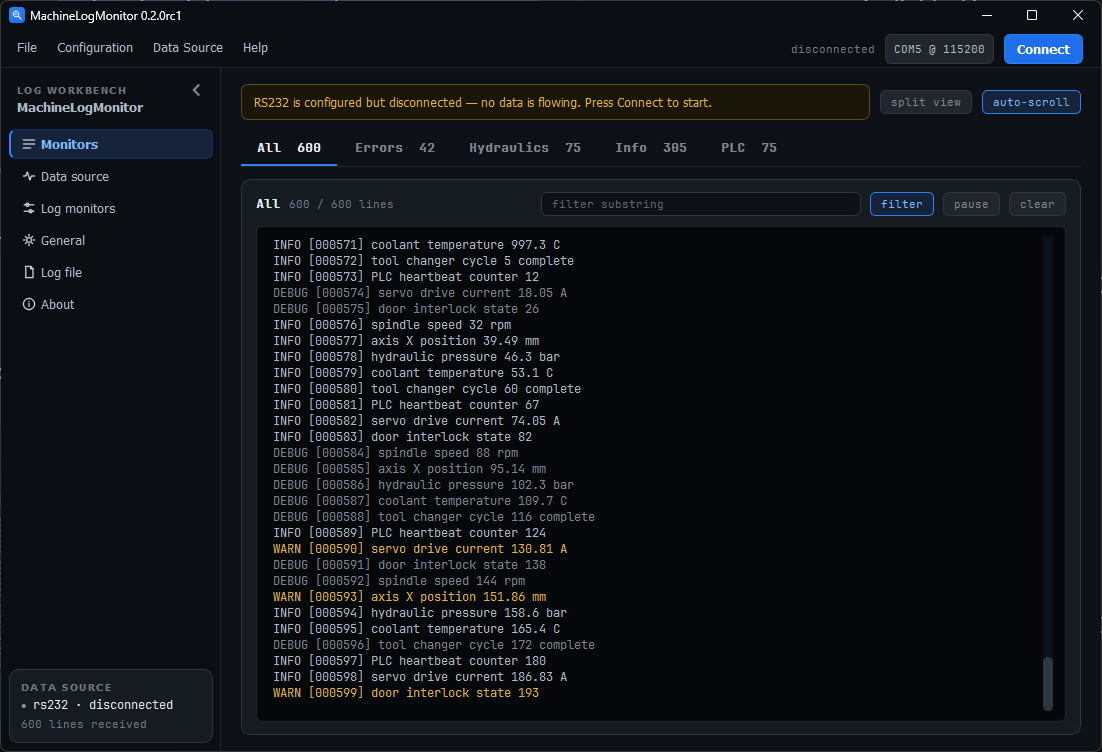
Screenshot einer Log-Monitor-Software mit Statusmeldungen
MachineLogMonitor 0.2.0rc1 LOG WORKBENCH Monitors Data source Log monitors General Log file About RS232 is configured but disconnected — no data is flowing. Press Connect to start. All 600 Errors 42 Hydraulics 75 Info 305 PLC 75 All 600 / 600 lines INFO [000571] coolant temperature 997.3 C INFO [000572] tool changer cycle 5 complete INFO [000573] PLC heartbeat counter 12 DEBUG [000574] servo drive current 18.05 A INFO [000576] spindle speed 37 rpm INFO [000577] axis X position 39.49 mm INFO [000578] hydraulic pressure 46.3
in „MachineLogMonitor – Textlogs von RS232, CAN und CAN-Trace-Dateien mehrere gefilterte Ansichten“ · Projekte & Code · · Screenshots
-
PDF
Transistortester093k.pdf
2150nF 2% 2149nF 2% 22µF 21,94µF 25,61µF 16% 21,92µF 0% 21,41µF 3% 21,41µF 3% 16% 0% 1% 1% 47µF 47,5µF 55,29µF 47,30µF 46,70µF 46,9µF 100µF 97,5µF 112,94µF 15% 91,30µF 6% 91,7µF 6% 91,3µF 6% 220µF 229µF 272,69µF 19% 219,2µF 5% 219,2µF 5% 219,2µF 5% 28% 0% 1% 1% 1000µF 1071µF 1371,95µF 1076µF 1063µF
-
PDF
Transistortester094k.pdf
2150nF 2% 2149nF 2% 22µF 21,94µF 25,61µF 16% 21,92µF 0% 21,41µF 3% 21,41µF 3% 16% 0% 1% 1% 47µF 47,5µF 55,29µF 47,30µF 46,70µF 46,9µF 100µF 97,5µF 112,94µF 15% 91,30µF 6% 91,7µF 6% 91,3µF 6% 220µF 229µF 272,69µF 19% 219,2µF 5% 219,2µF 5% 219,2µF 5% 28% 0% 1% 1% 1000µF 1071µF 1371,95µF 1076µF 1063µF
-
Datei
Random.asm
durch User eingriff ; B Anfangswert zufällig wählen ( SRAM soll da funktionieren ) ; C Externe IRQ wie RC combination ; ; Sonst erhält man immer den gleichen Endwert .NOLIST .include "4433def.inc" .LIST ; .DEF Carry = r16 .DEF MR = r20 .DEF Noise_L = r22 .DEF Noise_H = r23 .DEF Noise_HH = r24 .DEF Noise_HHH
in „Pseudo zufallszahlen / Rausch Generator ( AVR Assy)“ · Projekte & Code ·
-
Datei
config.xml
Setting caption="8 MHz internal" CKSEL3="0" CKSEL2="1" CKSEL1="0" CKSEL0="0"/> <Setting caption="ext RC 0.1-0.9 MHz" CKSEL3="0" CKSEL2="1" CKSEL1="0" CKSEL0="1"/> <Setting caption="ext RC 0.9-3.0 MHz" CKSEL3="0" CKSEL2="1" CKSEL1="1" CKSEL0="0"/> <Setting caption="ext RC 3.0-8.0 MHz" CKSEL3="0" CKSEL2=
in „Fuseeditor, grafische Benutzeroberfläche für AVRdude“ · Projekte & Code ·
-
Datei
Hysterese_4.asm
Schwellwertflag 6 setzen... cbr SW_FLAGS,1<<SWF_7 ;...ansonsten Schwellwertflag 7 loeschen... rjmp sw_5 ;...und naechsten Schwellwert pruefen set_sw_6: sbr SW_FLAGS,1<<SWF_6 ;Schwellwertflag 6 setzen sw_5: cpi AKKU_L,low(W_PEGEL_5) ;10-Bit ADC-Wert mit Schwellwertpegel 5... ldi A,high (W_PEGEL_5) ;... cpc AKKU_H,A ;...vergleichen... brsh set_sw_5 ;...falls >=, Schwellwertflag 5 setzen... cbr SW_FLAGS,1<<SWF_6 ;...ansonsten Schwellwertflag 6 loeschen... rjmp sw_4 ;...und naechsten Schwellwert pruefen set_sw_5: sbr SW_FLAGS,1<<SWF_5 ;Schwellwertflag
in „ATtiny26 Balkenanzeige ( Hysterese ) mit acht Schaltschwellen (ASM)“ · Projekte & Code ·
-
Datei
ws2812c.asm
------------------------------------------------------------------------------ ;USING ATTINY1614 @ 5V/20MHz, WS2812B LED STRIP ;FUSE: INT.RC OSC20 ;PORT-Belegung: I/O-A0: UPDI INP-B0: ; INP-A1: INP-B1: ; INP-A2: INP-B2: ; INP-A3: INP-B3: ; OUT-A4: WS2812 DATA ; INP-A5: ; INP-A6: ; INP-A7: .EQU LEDCN
in „WS2812 control @ ATTiny1614 (Assembler)“ · Projekte & Code ·
-
Datei
avr-video-8-8.asm
Steuerzeichen CR, LF, FF ; - Cursorpositionierung, Scrollen ; ; - Läuft auf dem ATMEGA-8 mit dem internen 8MHz RC-Oscillator. ; - keine externen Bauteile ausser drei Widerständen ; zur Pegelanpassung des Videosignales. ; ;Dieses Programm muss in den ATMEGA-8 geflasht werden. ;Es muss die Fuse-Einstellung 8MHZ int.RC-Clk
-
Datei
irmp-3.2.3-melinera.diff
_0_PAUSE_TIME * MAX_TOLERANCE_30 + 0.5) + 1) +# define MELINERA_1_PULSE_LEN_MIN ((uint_fast8_t)(F_INTERRUPTS * MELINERA_1_PULSE_TIME * MIN_TOLERANCE_30 + 0.5) - 1) +# define MELINERA_1_PULSE_LEN_MAX ((uint_fast8_t)(F_INTERRUPTS * MELINERA
in „IRMP - Infrared Multi Protocol Decoder“ · Projekte & Code ·
-
Datei
IS52Basic.a51
*************************** ; CR1: CJNE R3,#03H,CR11 ;NEED THIS MUCH RAM CR11: ;hier JC CRST JNC $+5 ljmp CRST MOV DPTR,#MEMTOP ;SAVE MEMTOP ACALL S31DP2 ;SAVE MEMTOP AND SEED RCELL ACALL CNEW ;CLEAR THE MEMORY AND SET UP POINTERS ; CR2: ACALL RC1 ;SET UP STACKS IF NOT DONE ; LCALL AXTAL0 ;DO THE CRYSTAL
in „Layout für MCS51 Experimentierboard“ · Projekte & Code ·
-
Datei
IS52Basic.a51
*************************** ; CR1: CJNE R3,#03H,CR11 ;NEED THIS MUCH RAM CR11: ;hier JC CRST JNC $+5 ljmp CRST MOV DPTR,#MEMTOP ;SAVE MEMTOP ACALL S31DP2 ;SAVE MEMTOP AND SEED RCELL ACALL CNEW ;CLEAR THE MEMORY AND SET UP POINTERS ; CR2: ACALL RC1 ;SET UP STACKS IF NOT DONE ; LCALL AXTAL0 ;DO THE CRYSTAL
in „Layout für MCS51 Experimentierboard“ · Projekte & Code ·
-
Datei
IS51Basic133.a51
ACALL S31DP2 ;SAVE MEMTOP AND SEED RCELL ACALL CNEW ;CLEAR THE MEMORY AND SET UP POINTERS ; CR2: ACALL RC1 ;SET UP STACKS IF NOT DONE ; LCALL AXTAL0 ;DO THE CRYSTAL MOV A,MT1 ;GET THE RESET BYTE CJNE A,#5,CR20 LCALL 4039H CR20: JNC BG1 ;CHECK FOR 0,1,2,3, OR 4 JNB ACC.0,BG3 ;NO RUN IF WRONG TYPE MOV DPTR
in „Layout für MCS51 Experimentierboard“ · Projekte & Code ·
-
Datei
ir-nec.c
************************ * (C) Bernhard Michler 2009 * Based on ideas and code of Peter Danneggers rc5 decoder * * File : ir_nec.c * Created : August 2009 * Author(s) : Bernhard Michler * * * DESCRIPTION: * Routines for IR receivers, decoding the ancient the widely spread * Japanese NEC code. * *****
-
Datei
AVRrescue.c
_3 0b01011011 // 3 #define DIGIT_4 0b00011110 // 4 #define DIGIT_5 0b01011101 // 5 #define DIGIT_6 0b01111101 // 6 #define DIGIT_7 0b00001011 // 7 #define DIGIT_8 0b01111111 // 8 #define DIGIT_9 0b01011111 // 9 #define DIGIT_A 0b00111111 // A #define DIGIT_B 0b01111100
in „AVR-Rescue: standalone Parallel HV-Programmer“ · Projekte & Code ·
-
PDF
readme.pdf
entsteht ein unschöner Treppeneffekt im Verlauf der Spannungskurve. (Bei der Messung von Spannung bis 5V beträgt dieAuflösung bis zu 20mV, bei Spannungen von 14V treten Sprünge von ca. 50mV zwischen benachbarten Messwerten auf.) Daher setze ich eine externe Referenzspannung ein. Um von Spannungsschwankungen
in „Messung von AKKU-(Entlade-)Kapazitäten mit ATTINY24 in C“ · Projekte & Code ·
-
Datei
VU-Meter.c
www.mikrocontroller.net/topic/419372 - dort ist die HW mit einem Tiny13 beschrieben * * Taktfrequenz 8MHz intern RC-Oszillator * Autotrigger des ADC durch TIMER0_OVL --> Samplefrequenz 31.25 kHz, * LED MUX Charlie-Plexing * Peak-Hold Anzeige für ca. 500ms * ADC input an PB4 (ADC2) mit ca. 0.55V Offset durch Spannungsteiler
in „VU-Meter mit Attiny13a statt LM3916“ · Projekte & Code ·
-
PDF
PWM_Controller_Manual_ohne_EEPROM.pdf
Kanal 2 R/W PWM Kanal - Wert 3 PWM Kanal 3 R/W PWM Kanal - Wert 4 PWM Kanal 4 R/W PWM Kanal - Wert 5 PWM Kanal 5 R/W PWM Kanal - Wert 6 PWM Kanal 6 R/W PWM Kanal - Wert 7 PWM Kanal 7 R/W PWM Kanal - Wert 8 PWM Kanal 8 R/W PWM Kanal - Wert 9 PWM Kanal 9 R/W PWM Kanal - Wert 0A PWM Kanal 10 R/W PWM Kanal
in „18- Kanal PWM Controller TWI(IIC)Interface FW. V.3“ · Projekte & Code ·
-
Datei
graphical_avrnetio.py
sg(netio,'setport 4.' + ('1' if Output[3]['bg'] == color_off_bg else '0') ) #einschalten def toggle5(): sg(netio,'setport 5.' + ('1' if Output[4]['bg'] == color_off_bg else '0') ) #einschalten def toggle6(): sg(netio,'setport 6.' + ('1' if Output[5]['bg'] == color_off_bg else '0') ) #einschalten def
in „AVR NET-IO - Zugriff und Loggen mit Python, mit grafischer Benutzeroberfläche“ · Projekte & Code ·
-
Datei
DUO_LED_12.asm
;.equ = PORTA0 ; ;.equ = PORTA1 ; ;.equ = PORTA2 ; ;.equ = PORTA3 ; ;.equ = PORTA4 ; ;.equ = PORTA5 ; ;.equ = PORTA6 ; ;.equ = PORTA7 ; ; ;.equ = PORTB0 ; ;.equ = PORTB1 ; ;.equ = PORTB2 ; ;.equ = PORTB3 ; .equ DLED_GN = PORTB4 ;DUO-LED_Grün .equ DLED_RT = PORTB5 ;DUO-LED_Rot ;.equ = PORTB6 ; ;.equ
-
Datei
libsht.c
2006-07-17 NA - Adjusted timing in measurement - changed data transfer in calc_sht; 2006-07-20 0v1rc - Included heating element code 2006-08-05 0v1 - Some additional cleanup - homogenized function names; */ #include <avr/io.h> //Microcontroller specific library, e.g. port definitions #include <math.h
in „Lib für Sensirion SHT1x Sensor an AVR“ · Projekte & Code ·
-
PDF
DE2012010361.pdf
18 RSSF 4 ISP_D 4 17 DCF- 1mH PGED1/RB0/RP0 RB8/RP8 5 ISP_C 5 16 PWM2 PGEC1/RB1/RP1 RB7/RP7 14 J2 RB6/RP6 15 U1TX ISP dsPIC33FJ32 VCC 1 GP202xSP R20 VCC 14 RB5/RP5 RB3/RP3/AN5 7 LED+ 220R 1 U3 2 2 21 3 4 3 RB10/RP10 1 LED1 R17 22 3 5 6 4 RB11/RP11 AN1/RA1
-
Datei
IS51Basic.ASM
SEED RCELL ACALL CNEW ;CLEAR THE MEMORY AND SET UP POINTERS ; CR2: ACALL RC1 ;SET UP STACKS IF NOT DONE ; LCALL AXTAL0 ;DO THE CRYSTAL MOV A,MT1 ;GET THE RESET BYTE CJNE A,#5,CR20 LCALL 4039H CR20: JNC BG1 ;CHECK FOR 0,1,2,3, OR 4 JNB ACC.0,BG3 ;NO RUN IF WRONG TYPE MOV DPTR
in „Layout für MCS51 Experimentierboard“ · Projekte & Code ·
-
PDF
PWM_Controller_Manual_normal.pdf
Kanal 2 R/W PWM Kanal - Wert 3 PWM Kanal 3 R/W PWM Kanal - Wert 4 PWM Kanal 4 R/W PWM Kanal - Wert 5 PWM Kanal 5 R/W PWM Kanal - Wert 6 PWM Kanal 6 R/W PWM Kanal - Wert 7 PWM Kanal 7 R/W PWM Kanal - Wert 8 PWM Kanal 8 R/W PWM Kanal - Wert 9 PWM Kanal 9 R/W PWM Kanal - Wert 0A PWM Kanal 10 R/W PWM Kanal
in „18- Kanal PWM Controller TWI(IIC)Interface FW. V.3“ · Projekte & Code ·
-
PDF
PWM_Controller_Manual.pdf
. TWI - CMD [HEX] Funktion Notes 0 ── none 1 PWM Kanal 1 2 PWM Kanal 2 3 PWM Kanal 3 4 PWM Kanal 4 5 PWM Kanal 5 6 PWM Kanal 6 7 PWM Kanal 7 8 PWM Kanal 8 9 PWM Kanal 9 0A PWM Kanal 10 0B PWM Kanal 11 0C PWM Kanal 12 0D PWM Kanal 13 0E PWM Kanal 14 0F PWM Kanal 15 10 PWM Kanal 16 11 PWM Kanal 17 HB
in „PWM- Controller 18- Kanal TWI- Bus Proj.“ · Projekte & Code ·
-
Datei
BASIC131-PS3.a51
ACALL S31DP2 ;SAVE MEMTOP AND SEED RCELL ACALL CNEW ;CLEAR THE MEMORY AND SET UP POINTERS ; CR2: ACALL RC1 ;SET UP STACKS IF NOT DONE ; LCALL AXTAL0 ;DO THE CRYSTAL MOV A,MT1 ;GET THE RESET BYTE CJNE A,#5,CR20 LCALL 4039H CR20: JNC BG1 ;CHECK FOR 0,1,2,3, OR 4 JNB ACC.0,BG3 ;NO RUN IF WRONG TYPE MOV DPTR
in „Spaß mit Kloeckner-Moeller PS3 in BASIC(?)“ · Projekte & Code ·
-
Datei
version_1p3_assembler.asm
ACALL S31DP2 ;SAVE MEMTOP AND SEED RCELL ACALL CNEW ;CLEAR THE MEMORY AND SET UP POINTERS ; CR2: ACALL RC1 ;SET UP STACKS IF NOT DONE ; LCALL AXTAL0 ;DO THE CRYSTAL MOV A,MT1 ;GET THE RESET BYTE CJNE A,#5,CR20 LCALL 4039H CR20: JNC BG1 ;CHECK FOR 0,1,2,3, OR 4 JNB ACC.0,BG3 ;NO RUN IF WRONG TYPE MOV DPTR
in „Spaß mit Kloeckner-Moeller PS3 in BASIC(?)“ · Projekte & Code ·
-
Datei
readme.txt
the download section, the kernel package is: http://www.kernel.org/pub/linux/kernel/v2.6/linux-2.6.5.tar.bz2 3) the Philips LPC22xx patch You could find the Philips LPC22xx patch for uClinux-2.6.5 from the maillist of uClinux.org. The mail title is "[PORT]uClinux and linux-2.6.5 patch for Philips LPC22xx
in „uCLinux Bootloader + Kernel für ARM LPC2294“ · Projekte & Code ·
-
PDF
FMeter-G431-Entwurf.pdf
- 160 MHz mit 8 - 11-stell. Ergebnis; lückenlose Messungen 0,1 Hz - 50 Hz @ 1 s: 8-stellig 50 Hz - 5 kHz @ 1: 9-stellig >= 5 kHz @ 1 s: 10-stellig >= 5 kHz @ 10 s: 11-stellig Hilfseingang F2: 0,1 Hz - 1 MHz mit 8-stell. Ergebnis/s; für 1 pps GPS-Signal Vorgabe der Messzeit von 0,001 – 25,000 s in
in „8-stelliger Frequenzzähler, reziprok, STM32F7xx“ · Projekte & Code ·
-
Datei
bas_main.bas
.2 = Eingang Radencoder Int0 Pind.3 = Eingang Radencoder Int1 Pind.4 = Motor2 Pwm Timer1 Pwrmb Pind.5 = Motor1 Pwm Timer1 Pwrma Pind.7 = Testpin 10ms Int Timer 0 = Sony Fernsteuerung Cntrl - S - Code Bzw. Sircs - Code Sony Hat Keinen Rc5 - Code !!! Timer 1 = Pwm Fuer 2 Motoren Timer 2 = 10ms Interrupt
in „eine lanze für den bascom-avr-compiler brechen...“ · Projekte & Code ·
-
PDF
PWM_Controller_Manual_Basic.pdf
2 Save W Aktuellen Kanal Wert abspeichern C4 PWM Kanal 3 Save W Aktuellen Kanal Wert abspeichern C5 PWM Kanal 4 Save W Aktuellen Kanal Wert abspeichern C6 PWM Kanal 5 Save W Aktuellen Kanal Wert abspeichern C7 PWM Kanal 6 Save W Aktuellen Kanal Wert abspeichern C8 PWM Kanal 7 Save W Aktuellen Kanal
in „PWM- Controller 18- Kanal TWI- Bus Proj.“ · Projekte & Code ·