-
PDF
SAT-L1_Flight_Controller.pdf
1 2 3 4 5 6 +3.3V +3.3V +3.3V +3.3V +3.3V R2 R1 4.7k 6 8 4.7k ESP_EN U1 MPU_SCL 4 I D SCK D V ESP_EN ESP32-WROOM-32E ESP_IO0 MPU_SDA 3 D 2 SDI V U3 5 3 D 25 ESP_IO0 GND SDO BMP280 A J1 EN V IO0 +3.3V +3.3V 2 D D
in „Prüfung Schaltplan Flight Controller“ · Mikrocontroller und Digitale Elektronik ·
-
Bild
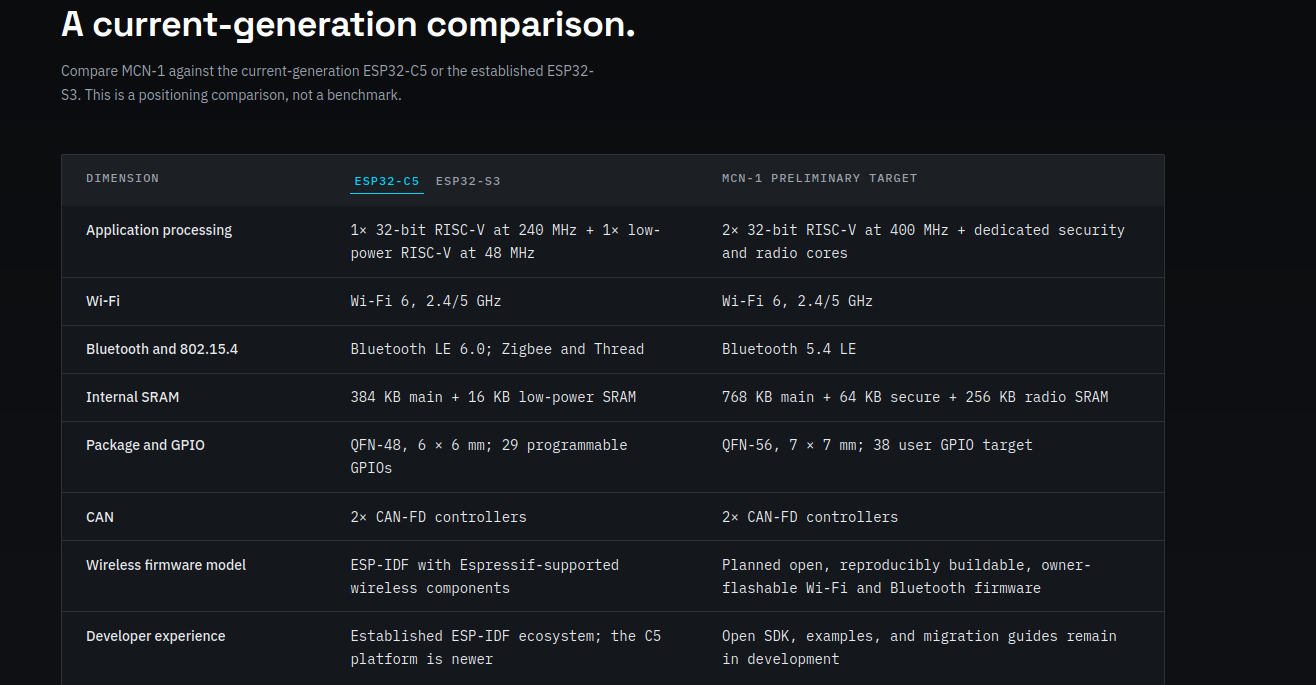
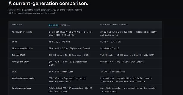
Vergleichstabelle ESP32-C5 gegen MCN-1
A current-generation comparison. Compare MCN-1 against the current-generation ESP32-C5 or the established ESP32-S3. This is a positioning comparison, not a benchmark. DIMENSION ESP32-C5 ESP32-S3 MCN-1 PRELIMINARY TARGET Application processing 1x 32-bit RISC-V at 240 MHz + 1x low-power RISC-V at 48 MHz 2x 32-bit RISC-V at 400 MHz + dedicated security and radio cores Wi-Fi Wi-Fi 6, 2.4/5 GHz Wi-Fi 6, 2.4/5 GHz Bluetooth and 802.15.4 Bluetooth LE 6.0; Zigbee and Thread Bluetooth 5.4 LE Internal SRAM 384 KB
in „ESP32-S31 in Massenproduktion, MERICRON als ESP32-Alternative uvam“ · Mikrocontroller und Digitale Elektronik · · Screenshots
-
Datei
BLE_Keyboard5.ino
/* Bluetooth BLE Keyboard - Deutsches Tastaturlayout (QWERTZ) ESP32 wird per USB an den Sender-PC angeschlossen und sendet Tastenanschlaege per BLE an den Ziel-Rechner. Benutzung mit minicom (Linux) als Sender: minicom -D /dev/ttyUSB0 Hardware: ESP32 WROOM Framework
in „Remote Tastatur“ · Projekte & Code ·
-
Bild
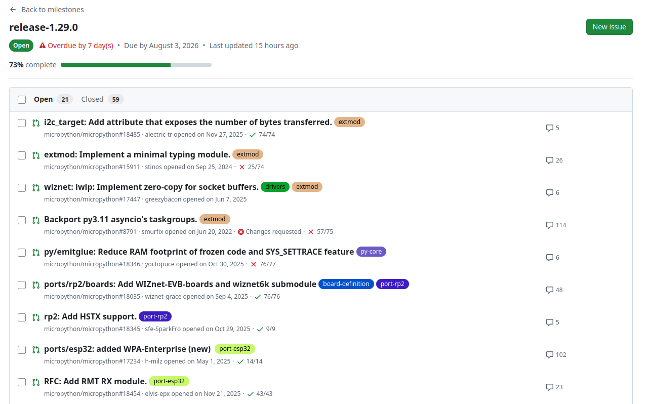
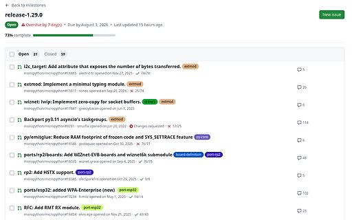
Liste von GitHub Issues zu MicroPython
release-1.29.0 Open 21 Closed 59 i2c_target: Add attribute that exposes the number of bytes transferred. extmod micropython/micropython#18485 electric-tr opened on Nov 27, 2025 74/74 extmod: Implement a minimal typing module. extmod micropython
in „MicroPython-Updates, Abschaltung von 2G-Netzen, BaoChip und AI-Software“ · Mikrocontroller und Digitale Elektronik · · Screenshots
-
Bild
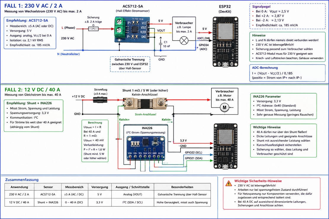
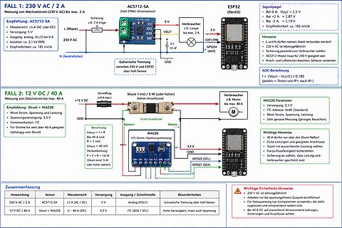
Vergleich zweier Messschaltungen für AC und DC Strom
Wechselstrom (230 V AC) bis max. 2 A Empfehlung: ACS712-5A L (Phase) 230 V AC N (Neutralleiter) ACS712-5A ESP32 (DevKit) Signalpegel Bei 0 A: VOUT = 2,5 V Bei +2 A: VOUT = 2,8 V Bei -2 A: VOUT = 2,13 V Empfindlichkeit: ca. 185 mV/A Verbraucher z.B. Lampe 5 V 5 V C1 10 nF VOUT bis max. 2 A GPIO1_CH4 GND Galvanische Trennung zwischen 230 V und ESP32 über Hall-Sensor FALL 2: 12 V DC / 40 A Messung von Gleichstrom bis max. 40 A Empfehlung: Shunt + INA226 +12 V DC GND Shunt 1 mOhm / 5 W (oder höherer) Kelvin-Anschluss Verbraucher z.B. Motor INA226
in „Was für eine KI verwendet ihr für Schaltungsentwurf“ · /dev/null · · Diagramme
-
PDF
CPSignal_Wallbox_mit__C.pdf
Stromvorgabe per PWM Im üblichen Bereich von 10 bis 85 % gilt: Maximalstrom [A] = Tastgrad [%] × 0,6 Beispiele: Maximalstrom Tastgrad 6 A 10 % 10 A 16,7 % 16 A 26,7 % 20 A 33,3 % 32 A 53,3 % Oberhalb 85 % gilt eine andere Kennlinie. 5 % ist für High-Level-Kommunikation reserviert und sollte nicht als
in „saubere Rechtecksignalpegelwandlung 0/5V auf +12/-12V“ · Mikrocontroller und Digitale Elektronik ·
-
PDF
Elektronusches_Uhren_Relay-V4.pdf
------~~-- 1 . 01 j1 . ..I ~ f ! ;-c ~ ~ dl ~ . r. 1 14 i j~ ' ) 14 ) ' 112 !~J- 4 13 4 D 11 300-48.3101.0310 1 ,t 6 11 6 90 ~~~~--~~-----------------'il i1 ~ 7 10 7 B 1 9 Elektron. Uhrenrelais :-;-':.] :i : r 1 !I * 32 4 --4-8 .3 70 7
in „Polwechselnden Impuls mit Transistoren verstärken“ · Analoge Elektronik und Schaltungstechnik ·