-
PDF
DOC004015493.pdf
20.5CFM Note.245W 146W 143W 147.8W POWER OUTPUT ConvectionNote.38.6W 98.4W 99W 98.2W RIPPLE & NOISE (max.) Note.60mVp-p 80mVp-p 120mVp-p 60mVp-p 100mVp-p 100mVp-p 60mVp-p 80mVp-p 100mVp-p 80mVp-p 100mVp-p 120mVp-p VOLTAGEADJ. RANGE CH1:5 ~ 5.5V VOLTAGE TOLERANCE Note.5±2.0% ±5.0% -5,+7% ±2.0% ±5.0% -4,
in „Willtek Schlumberger Stabilock 4031 4032“ · HF, Funk und Felder ·
-
Bild
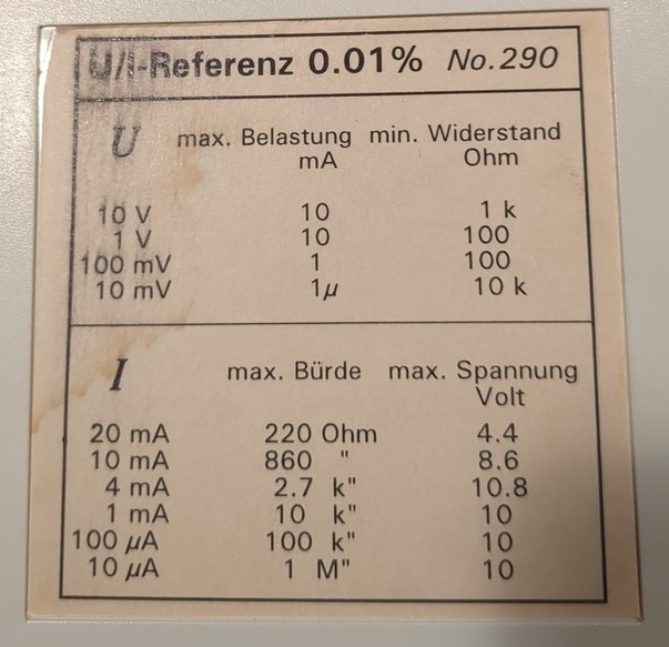
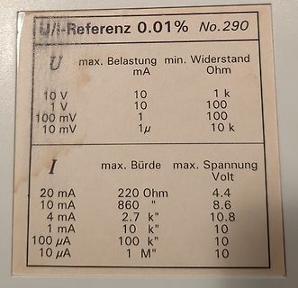
Typenschild mit Messwerten für Spannung und Strom
U/I-Referenz 0.01% No.290 U max. Belastung min. Widerstand Ohm 10 V 10 1 k 1 V 10 100 100 mV 1 100 10 mV 1µ 10 k I max. Bürde max. Spannung Volt 20 mA 220 Ohm 4.4 10 mA 860 " 8.6 4 mA 2.7 k" 10.8 1 mA 10 k" 10 100 µA 100 k" 10 10
in „[V] Referenzspannungsquelle /-stromquelle“ · Markt · · Fotos
-
PDF
Schaltplan__1_.pdf
_RST R15 +3V3 1 2 3 4 18 31 100uF +3V3 C6 + C25 19VBG XO 30 1 2 10k R AGND XI/CLKIN U1 X _ W5500_TOCAP 20 TOCAP GND 29 R16 C4 C2 5 _ U +3V3A2 21 28 +3V3 C16 25MHz W5500_INT +3V3 100uF C1 1 GND 100nF GND + 0 O 100nF 1V2O 22AVDD VDD
in „Platinen Prüfung“ · Platinen ·
-
PDF
SCH_Schematic1_2026-11-01.pdf
C14 100nF ETH_OUT_RX+ 3 RD+ J5 GND 4 3 GND +3V3A 100nF R29 1CT:1CT J4 +3V3A RXP4 GND C26 ETH_OUT_TX- 2 TD- J3 RX+ 100nF 100nF +3V3A J1 +3V3A2 1 2 C12 GND 4 J2 TX- R8 GND 1CT:1CT J8 ETH_OUT_TX+ 1 TD+ J1 TX+
in „Platinen Prüfung“ · Platinen ·
-
PDF
RS-25-SPEC.pdf
Short circuit / Overload / Over voltage Cooling by free air convection LED indicator for power on 100% full load burn-in test All using 105 ℃ long life electrolytic capacitors Withstand 300VAC surge input for 5 second High operating temperature up to 70 ℃ Withstand 5G vibration test No load power consumption
in „Willtek Schlumberger Stabilock 4031 4032“ · HF, Funk und Felder ·
-
PDF
RS-50-spec.pdf
Short circuit / Overload / Over voltage Cooling by free air convection LED indicator for power on 100% full load burn-in test All using 105℃ long life electrolytic capacitors Withstand 300VAC surge input for 5 second High operating temperature up to 70 ℃ Withstand 5G vibration test No load power consumption
in „Willtek Schlumberger Stabilock 4031 4032“ · HF, Funk und Felder ·
-
Bild
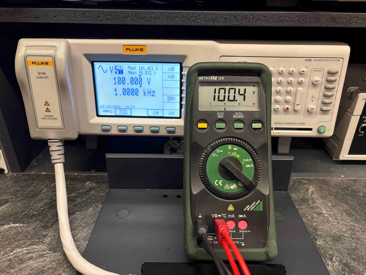
Fluke Kalibrationssystem und Multimeter
FLUKE 9105 LEAD KIT Peak 141.421 V Mean 30.032 V 100.000 V 1.0000 kHz 29/10/2026 19:53 ZERO FLUKE 9100 CALIBRATION SYSTEM METRA HM 12S 100.4 V AUTO MAN OFF DATA MIN/MAX ON CE
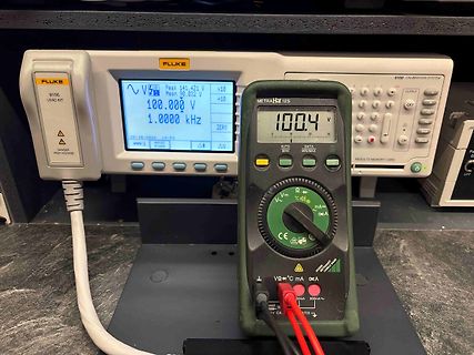
in „[V] Verschiedene Digitalmultimeter Handmultimeter – Gossen Metrawatt, Wavetek, Voltcraft, Maxcom“ · Markt · · Fotos
-
Datei
ESP_Gleissteuerung_29_10_26_A_WS_2.ino
-> <g id="coordinates"> <text class="coordLabel" x="0" y="16">0</text> <text class="coordLabel" x="100" y="16">100</text> <text class="coordLabel" x="200" y="16">200</text> <text class="coordLabel" x="300" y="16">300</text> <text class="coordLabel" x="400" y="16">400</text> <text class="coordLabel" x
-
Bild
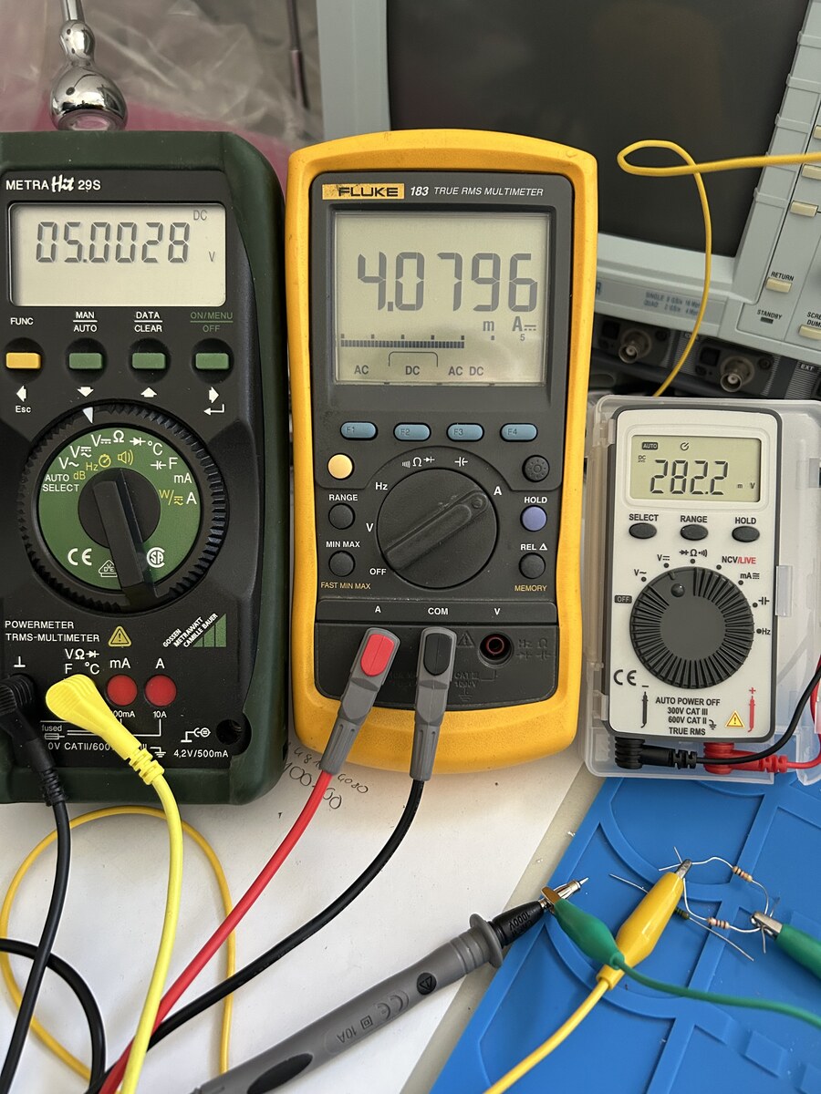
Drei Multimeter und Messaufbau auf Werkstattunterlage
METRA HM 29S 05.0028 DC V MAN AUTO DATA CLEAR ON/OFF FUNC Ω + F mA W/A CE AUTO SELECT LOW LIMIT 100mA 0V CAT II 600V 4.2V/500mA FLUKE 183 TRUE RMS MULTIMETER 4.0796 mA AC DC AC DC RANGE Ω A HOLD MIN MAX V REL A COM V CE AUTO POWER OFF 300V CAT II 600V CAT II RMS TRUE 282.2 SELECT RANGE
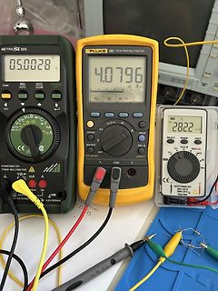
in „KiCAD: Erste Gehversuche - bitte um Feedback“ · Platinen · · Fotos
-
Datei
esp_Gleissteuerung_OK.ino
;font-weight:bold} .small{font-size:12px;color:#b9c7d3} #status{overflow-wrap:anywhere} svg{ width:100%;height:auto;display:block; background:#111;border-radius:8px } .grid{stroke:#777;stroke-width:.6} .coordLabel{fill:#7dd3fc;font:12px Arial,sans-serif;text-anchor:middle;pointer-events:none} .coordY