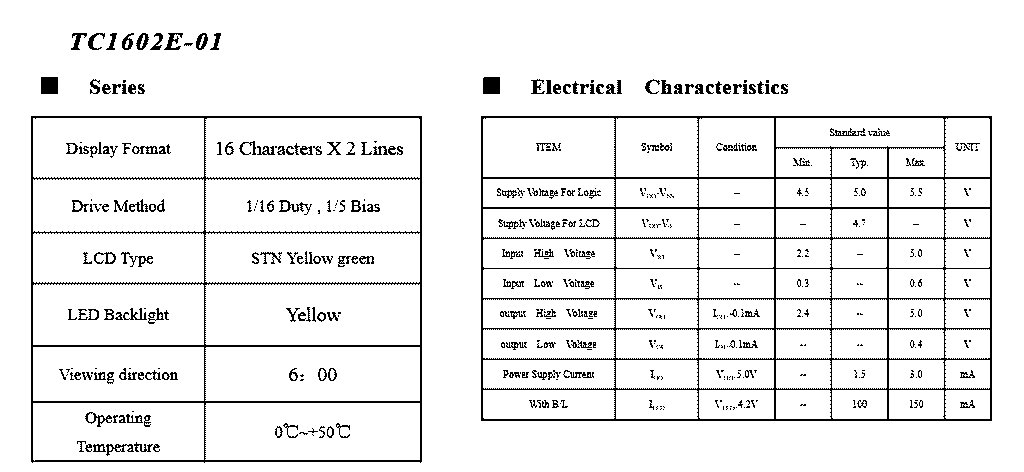
UNIT
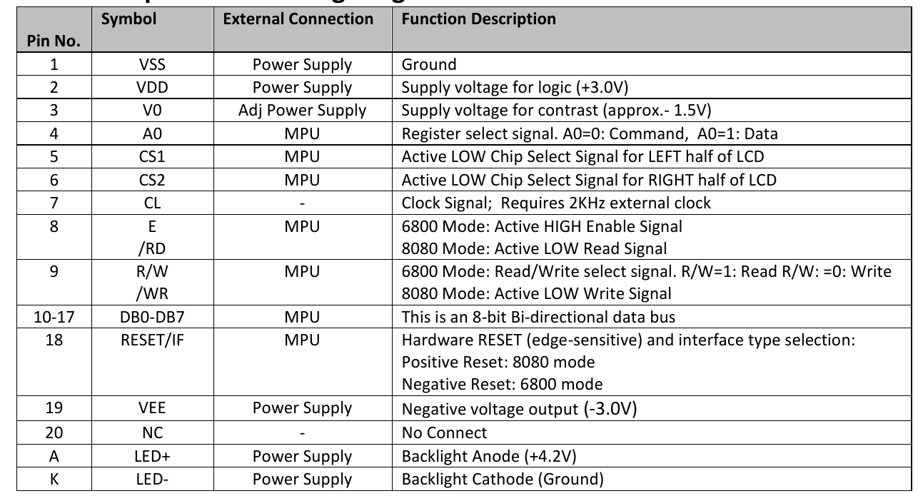
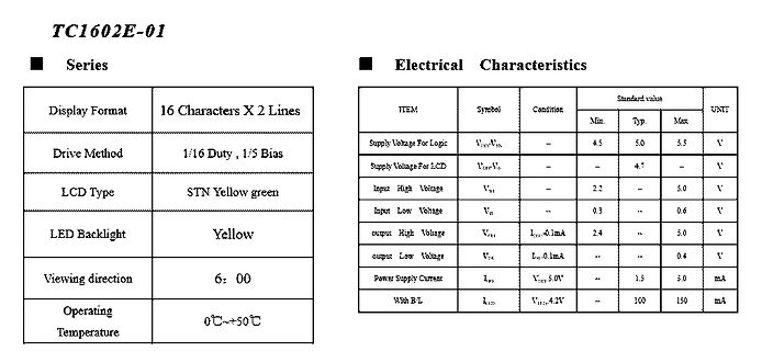
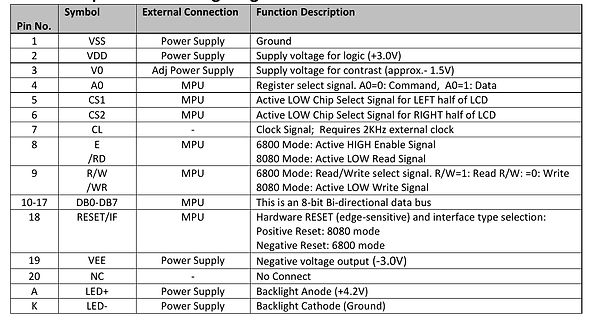
Supply Voltage For Logic VDD-VSS - 4.5 5.0 5.5 V
Supply Voltage For LCD VDD-VSS - 4.7 - V
Input High Voltage VIN - 2.2 - 5.0 V
Input Low Voltage VSS - 0.3 - 0.6 V
Output High Voltage VOH Iout=0.1mA 2.4 - 5.0 V
Output Low Voltage VOL Iout=0.1mA - - 0.4 V
Power Supply Current IPD VDD-VSS 1.5 3.0 mA
With
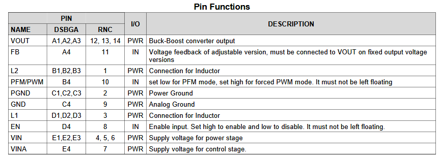
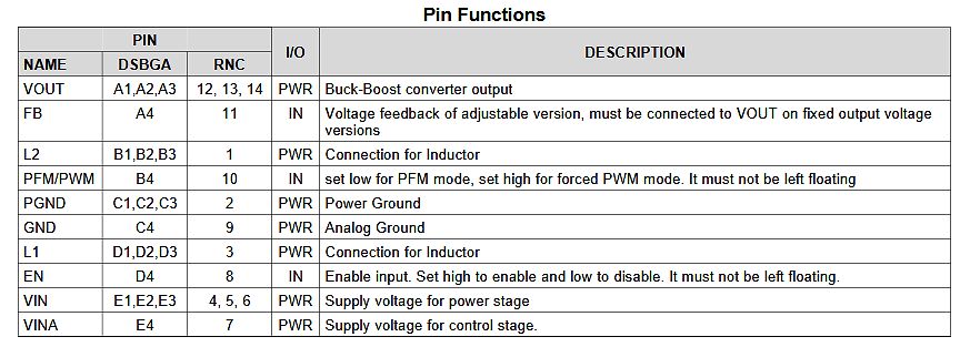
VOUT on fixed output voltage versions
L2 B1,B2,B3 1 PWR Connection for Inductor
PFM/PWM B4 10 IN set low for PFM mode, set high for forced PWM mode. It must not be left floating
PGND C1,C2,C3 2 PWR Power Ground
GND C4 9 PWR Analog Ground
L1 D1,D2,D3 3 PWR Connection for Inductor
EN D4 8 IN Enable input. Set high to enable and low to disable. It must not be left floating.
VIN E1,E2,E3 4, 5, 6 PWR Supply voltage for power stage
VINA E4 7 PWR Supply voltage for control stage.
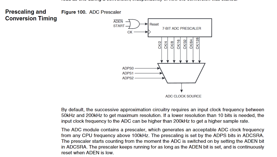
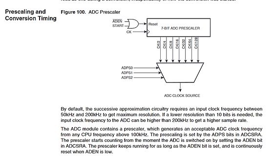
circuitry requires an input clock frequency between 50kHz and 200kHz to get maximum resolution. If a lower resolution than 10 bits is needed, the input clock frequency to the ADC can be higher than 200kHz to get a higher sample rate.
The ADC module contains a prescaler, which generates an acceptable ADC
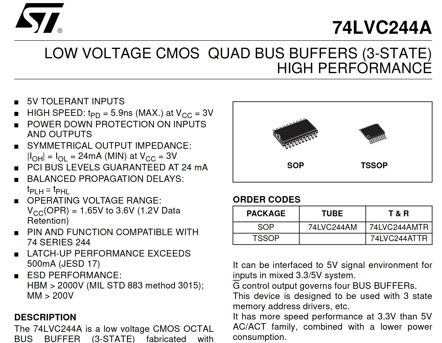
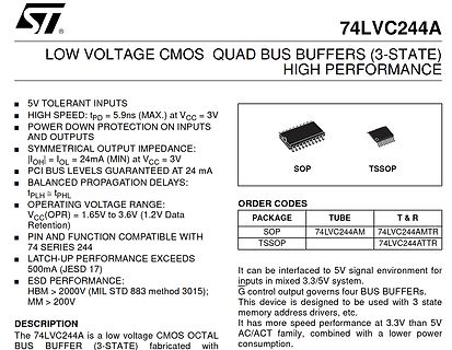
ST 74LVC244A LOW VOLTAGE CMOS QUAD BUS BUFFERS (3-STATE) HIGH PERFORMANCE 5V TOLERANT INPUTS HIGH SPEED: tPD = 5.9ns (MAX.) at VCC = 3V POWER DOWN PROTECTION ON INPUTS AND OUTPUTS SYMMETRICAL OUTPUT IMPEDANCE: |OHL
versions like Windows 11, requires a significant amount of system resources to run smoothly. On lower-end hardware, it can feel like it's constantly fighting for resources. 7. Lack of User Control: Sometimes, it feels like Windows is making decisions for you—like automatic updates or features
: unter Linux funktioniert, ohne massive Bastelei, kein HDMI 2.1 - gerade für Spieler, mit Mid- / High-End Ausrüstung ist das ein großes No-Go wenn bei 4K bei 60Hz Schluss ist, und das ohne Dyn-HDR. Da ist aber wiederrum nicht Linux dran schuld sondern das HDMI Konsortium und deren Lizenzpolitik - aber
wiringPiSetup(); gpio_num = i =0; pinMode (i, OUTPUT) ; for ( ;; ) { digitalWrite (i, HIGH); // On digitalWrite (i, LOW); // Off } return 0; } [/c] Lohn der Mühen ist das in der Abbildung gezeigte Schirmbild. 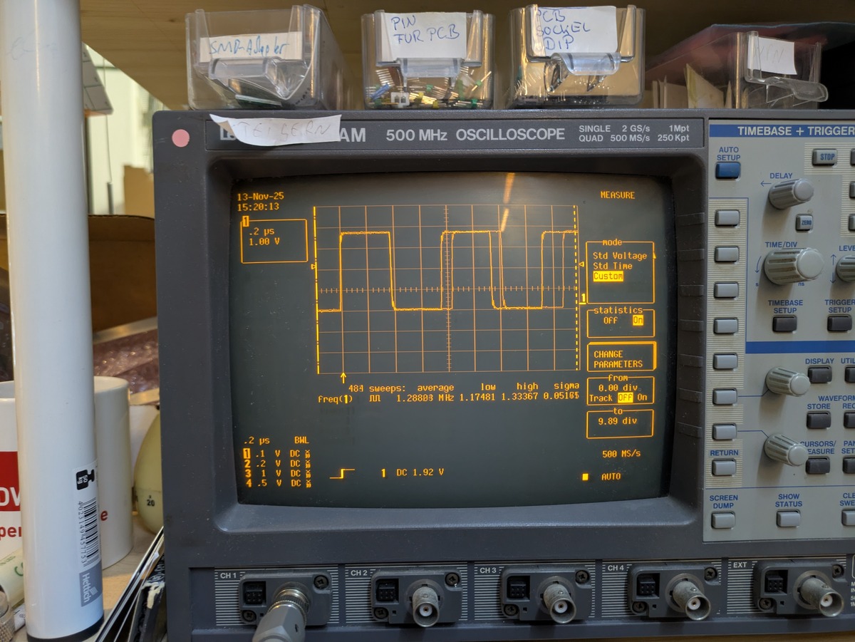 Zu beachten ist, dass
article directly here! Tutorials: ■ Connecting LAN Transformers (PDF) ■ The LAN-PoE Connection (PDF) ■ High Performance Low EMI Series (PDF) ■ RJ45 Through Hole Reflow Technology (PDF) CHECKED REVISION DATE (YYYY-MM-DD) GENERAL TOLERANCE METHODTION LuWe 003.000 2024-03-20 DIN ISO 2768-1m DESCRIPTION WE-RJ45LAN
oberen Nibble D4-D7 gefüttert werden will. Weil bei den ersten drei 30-er- Gruppen D0-D3 so wie so "low" "0" sind, ist es egal, ob das durch Portpegel oder äußere Beschaltung (Widerstände) auf GND geschieht. Das obere Nibble mit der "3" in der 30-er Gruppe wird immer von D4-D7 gelesen. Die Routine ist
"portb" statt "daten" out portb, temp ; PB0-PB3=Daten ... ori temp, 0b00010000 ; RS=high out daten,temp ; Ausgabe D4-D7-Daten-Nibble auf Port D0-D3 ... [/code] usw. Konsequent durchziehen, dann kannst du das über .equ-Änderungen auch anpassen.
also 20 mA fließen lassen könntest, dann vergiss die Transistoren und puffere das Signal nur mit "low coil power" bzw "high sensitive" Relais wie z.B. Finder 40.62.7.024.0000 (20mA) oder Hongfa HFD16 (10mA)
When RS485 mode is enabled, inverts the RTS line from active-high (default) to active-low. rs485_rts_on_delay When RS485 mode is enabled, sets the delay (in milliseconds) between data transmission starting
100% PWM buck (step-down) DC/DC converter, Minimum Drop Out 0.3V capable of driving a 5A load with high Fixed 180KHz Switching Frequency efficiency, low ripple and excellent line and 5A Constant Output Current Capability load regulation. Requiring a minimum Internal Optimize Power MOSFET number of external
Bildquelle: https://www.raspberrypi.com/news/raspberry-pi-flash-drive-available-now-from-30-a-high-quality-essential-accessory/ Als neuestes Werkzeug schickt man einen USB-Stick ins Rennen, der mit entweder 128 oder 256 GB Kapazität verfügbar ist: [c] It can sustain a write speed of 75MB/s (
until they can run software recognizing whether or not they’re printing a prohibited item, like the lower receiver of an AR-15 rifle/pistol. A registry of prohibited items would be listed by the state attorney general, updated annually. [/c] Zum Zeitpunkt der Abfassung ist völlig unklar, wie dies technisch
• Adjacent channel noise suppression (114 kHz) • Pilot canceller • Analog control of de-emphasis; High Cut Control (HCC) • Applicable as source selector for AM/FM/cassette switching • Separate interference noise detector • Integrated input low-pass filter for delayed noise blanking • Noise blanking at
the „ESC Y W“ command. A maximumcurrentof10mAcanbeswitchedperline.Thisgivetheopportunity to drive a low power LED in direct way. To source higher current please use an external transistor. EXTENDEDOUTPUTS It is possible to connect 1 to 32 chips like 74HC4094 to the eDIP (OUT1...OUT3), this is why it is
been connected if (currentVbusState == true) { // Start USB operations status = USB_Start(); LED_SetHigh(); } else { // Stop USB operations status = USB_Stop(); LED_SetLow(); } // Save state prevVbusState = currentVbusState; } } /** * Interrupt routine used to check VBUS status using the Real-Time Counter
Idee, den ADL5511 zu verwenden). Die Idee wäre, das Wandeln und Kopieren mit einem schnellen, low-noise, high slew-rate FDA zu machen. Für die Amplitudenerfassung ist die Phase ja egal :). In der Simulation habe ich bisher die ADA4927, ADA4932 und ADA4938 ausprobiert. Ich weiß, dass die FDA
1、Product Overview HDS10 condensation sensor switching element of the positive characteristics of low humidity sensitive only to high humidity sensitive work in the DC voltage, stable quality, reliability reached the international advanced level. Physical map Dimensions(Unit: mm) 2、Range of applications
NXP immobilizer system solutions Reduced system cost for high-security immobilizer designs NXP’s leading portfolio for immobilizer system includes a full range of security options for the transponder side, perfectly complemented by advanced basestation solutions
RoHS 标准 Welding Method: Reflow soldering Compliance with RoHS standards ◆ 采用高可靠性封装能量稳定 ◆体积小、功耗低、指向性好 High reliability packaging energy stabilizatSmall size, low power consumption, good directivity 2.应 用 范 围 ( Applications ) ◆油墨、UV 胶水、油漆等需要快速、高效固化的领域 Ink, UV glue, paint and other areas need fast and efficient
FTR-K1 SERIES POWER RELAY 2 POLES - 5A LOW PROFILE TYPE FTR-F1 Series n FEATURES l Low profile (height: 16.5mm) l DPST/DPDT 5A, TV-3 rating available l High insulation (due to its reinforced insulation construction) Insulation Distance (between
where voltages in excess of the supply voltage are common. With E LOW, one of the eight switches is selected (low impedance ON-state) by S0 to S2. With E HIGH, all switches are in the high-impedance OFF-state, independent of S0 to S2. The injection-current effect control
time of rainy weather From the classroom to the 2 cafeteria, the fox you campus 1.8 million to read. High efficiency: 83% (typical), sufficient 60 years old, fat East founder in 3 the east, announced the Spring Using solar cells 320,000 Reading Guo Shiqiang reiterated the Less peripherals: only one inductor selection criteria of the 53 million Reading Low-voltage battery protection function The input current can be adjusted by the inductance Sohu Scope of application What is the history and Funny n… culture of Wuxi County and the famous people? Solar
PE 1 2 3 4 br bl bk bk b b b b 1 4 2 3 Y1 T >150 454 143/15R 19 FLA 206 Control unit A3 DMS Sense Low X6/1 Sense High Common Vref X6/2 + Input - Input X6/7 X6/5 X5 13 X6/6 14 Y X Y X A D S S Q D T Q R X8/1 Sense Low Sense High Common Vref + Input X8/2 s u - Input X8/7 B X8/5 T X7 A 13 X8 /6 e a 14 r
Nischenthema. Sieht so aus. Simple Antennenverstärker sind gefragter ;-) Kann mich aber auch für low-tech-Themen begeistern. Wollte schon immer mal einen super-stromsparenden, schmalbandigen UHF-Regen.-Receiver mit 3-Port SAW-Filter aufbauen. Auch so ein 2- 4- Transistor Projekt. > Bastle damit
compilieren kann. Auf jeden Fall macht das Sinn. Wenn's kompliziert wird, gehe ich dreistufig vor. Erst "High-Level" in Matlab/Octave, dann in C/C++ auf dem PC und im letzten Schritt erst auf dem uC. Auch da nutze ich zunächst Testdaten vom PC, sonst wird die Fehlersuche zu mühsam. Hatte ich so beim FT8-Decoder
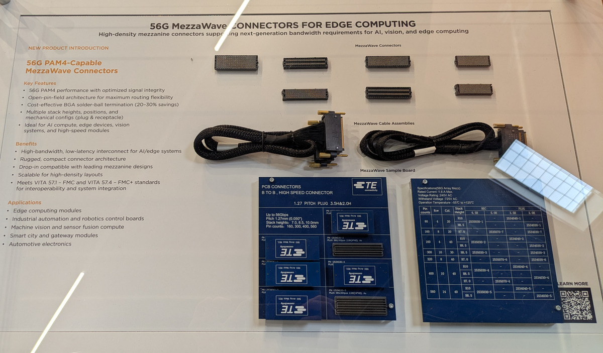
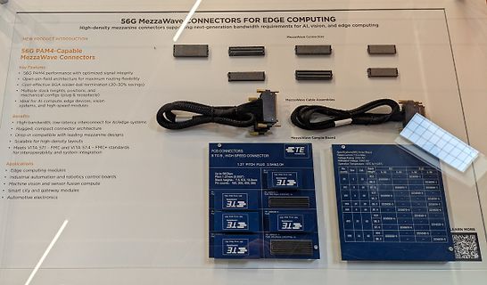
and mechanical configs (plug & receptacle)
Ideal for AI compute, edge devices, vision systems, and high-speed modules.
Benefits
High-bandwidth, low-latency interconnect for AI/edge systems
Rugged, compact connector architecture
Drop-in compatible with leading mezzanine designs
Scalable for high-density
normal operating temperature should be between 0° and 40°C. Never use the instrument in a room with high humidity (>95 %) or at very low temperatures (condensation water!). Manufacturer Consort bvba Parklaan 36 Tel (+32)(14)41 12 79 B2300 Turnhout Fax (+32)(14)42 91 79 Belgium E-mail: info@consort.be Warranty
contrast (approx. 1.5V)
4 A0 MPU Register select signal. A0=0: Command, A0=1: Data
5 CS1 MPU Active LOW Chip Select Signal for LEFT half of LCD
6 CS2 MPU Active LOW Chip Select Signal for RIGHT half of LCD
7 CL CL Signal; Requires 2KHz external clock
8 E MPU 6800 Mode: Active HIGH Enable Signal
9 /RD R/W 8080 Mode: Active LOW Read Signal
/RW 6800 Mode: Read/Write select signal. R/W=1: Read R/W: =0: Write
/WR 8080 Mode: Active LOW Write Signal
10-17 DB0-DB7 MPU This is an 8-bit Bi-directional data bus
18 RESET/IF MPU Hardware
DESCRIPTION OUTLINE DRAWING RD70HVF1C is a MOS FET type transistor specifically designed for VHF/UHF High power amplifiers 25.0±0.3 applications. 7.0±0.5 11.0±0.30 6.2±0.7 4.5±0.7 4-C2 1 FEATURES 2 High power and High Gain: 0 0 0 7 . 0 Pout>70W, Gp>10.6dB @Vds=12.5V,f=175MHz 1 9 1 Pout>50W, Gp>7.0dB @Vds=12.5V,f=520MHz 3 High Efficiency: 60%typ.on VHF Band 2-R1.6 ± 0.15 5.0±0.3 0-0.01 High Efficiency: 55%typ.on UHF Band 18.5±0.3 Integrated gate protection diode PIN 2. SOURCE 3. GATE 2 ± UNIT:mm APPLICATION 3 For output stage
Als nächste Erweiterungen sind unter anderem eine visuelle Anzeige der Schiebeschalter und der der HIGH/LOW-Pegel an den Steckbuchsen, das Speichern und Laden von Schaltungen sowie möglicherweise ein virtueller Signalprüfer vorgesehen. Mich würden besonders eure Meinungen zur technischen Umsetzung
(3.3V) (5V) USB Micro-AB Connector Figure 5.1. Power Switch With the switch in the AEM position, a low-noise 3.3 V LDO on the starter kit is used to power the EFM8UB2. This LDO is again pow- ered from the debug USB cable. The Advanced Energy Monitor is now connected in series, allowing accurate high-speed
Schaltung auch nicht der Hammer, aber ich würde das nicht so eng sehen. Es geht ja nicht darum ein High-End Audiogerät, am besten noch für die Serienproduktion, zu entwickeln, sondern einfach nur ein paar Bauteile zusammen zu stecken und mal sehen was raus kommt. Ein paar Töne werden schon raus kommen
LED-Geraffel was in dem ganzen Blinki-Blinki-Chichi verbaut ist. Die Typen des TO sind bestenfalls Low Current (die leuchten vermutlich bei 50µA erkennbar) - wir wissen es nicht - und bei den Widerständen hat er einfach einen Wert genommen der ihm brauchbar erschien. Ich habe mal eine LED aus meiner
stored program begins execution when FOCAL is given the GO command. This execution begins at the lowest line number in the stored program and will proceed from there to higher line numbers as the program logic allows. The running program can be stopped by the user, by FOCAL or by the program itself;
e.g. reverse polarity) LED 9 is flashing Device fault LED 9 lights permanently Battery voltage too low (Ubat<Uesp) LED 6 and 9 are flashing Pre-Conditioning LED 2, 4, 5 and 6 light permanently Battery fault LED 9 lights permanently * Low ambient temperature (LED3) can be signalized simultaneous at every
fps) at full frame and is specifically designed to capture fast-moving events and perform precise high‑speed measurements. Flash 8K (8K x 1K) achieves 1,800 fps, providing a powerful solution for high-end 3D laser profiling applications and high-speed, high-resolution inspection systems. [/c] #
Semiconductor is pleased to announce a global distribution partnership with Rutronik, making our nPZero™ ultra-low-power technology more accessible to customers and design engineers worldwide. Rutronik will represent two products from the nPZero platform: the nPZero G1S and our newest device, the nPZ2100. [/c]
a few external reactive elements between the gain select terminals, the circuit can function as a high-pass, low-pass, or G GAIN SELECT 3 12 G GAIN SELECT 2B 2A band-pass filter. This feature makes the circuit ideal for use as a video or pulse amplifier in communications, magnetic memories, G1B GAIN
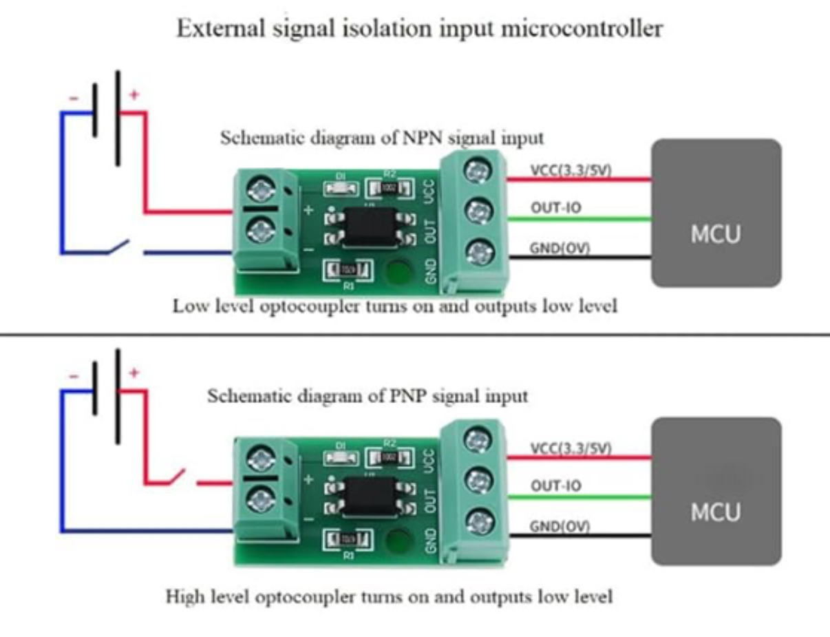
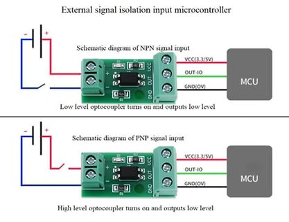
microcontroller
Schematic diagram of NPN signal input
DI R2 VCC(3.3/5V)
+ - OUT-IO
MCU
R1 GND(0V)
Low level optocoupler turns on and outputs low level
Schematic diagram of PNP signal input
High level optocoupler turns on and outputs low level
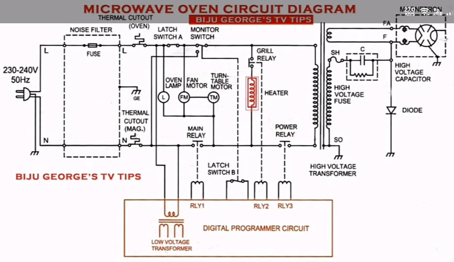
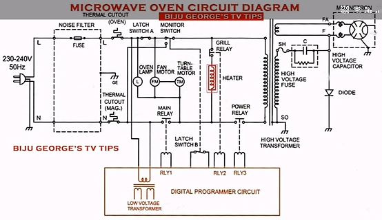
OVEN LAMP
FAN MOTOR
TABLE MOTOR
MAIN RELAY
LATCH SWITCH B
RIY1
RLY2
RLY3
DIGITAL PROGRAMMER CIRCUIT
LOW VOLTAGE TRANSFORMER
GRILL RELAY
HEATER
POWER RELAY
HIGH VOLTAGE FUSE
HIGH VOLTAGE TRANSFORMER
HIGH VOLTAGE CAPACITOR
DIODE
SO
F
description of HS����. �、�, in line with USB�.� specifications: one to four, the upstream port supports high-speed (HS) and full-speed (FS) channels, downstream ports support HS, ,FS and low-speed (LS) channels. �、�-bit microprocessor: Includes RISC-like architecture, USB optimized instruction set. �, TSSOP
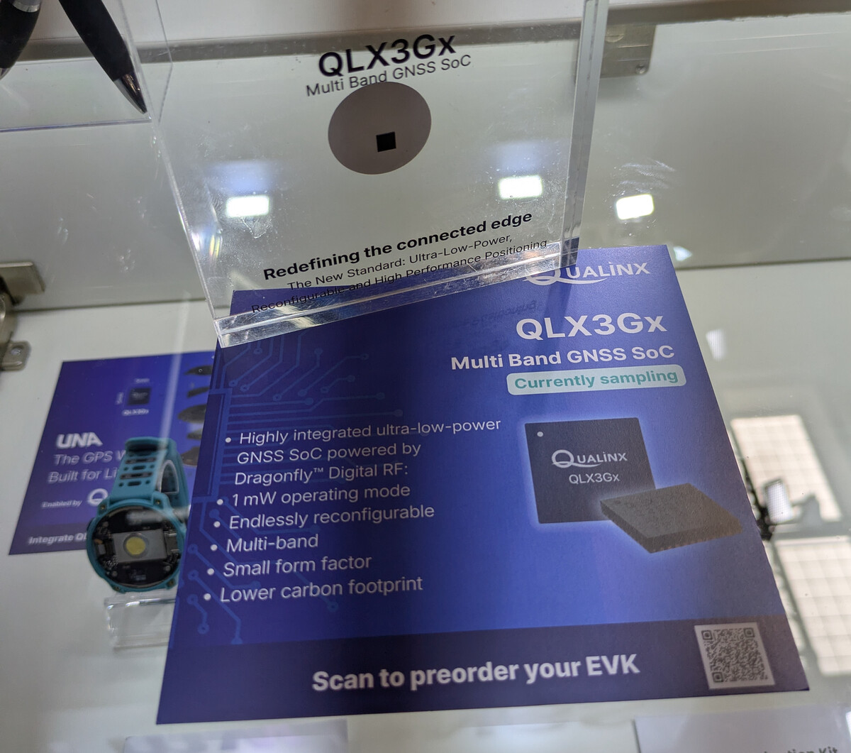
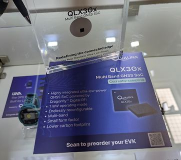
QLX3Gx Multi Band GNSS SoC
Redefining the connected edge
The New Standard: Ultra-Low-Power, Reconfigurable and High Performance Positioning
QUALINX
QLX3Gx
Multi Band GNSS SoC
Currently sampling
• Highly integrated ultra-low-power GNSS SoC powered by Dragonfly™ Digital RF;
• 1 mW operating mode
• Endlessly reconfigurable
• Multi-band
• Small form factor
• Lower carbon footprint
Scan to preorder your EVK
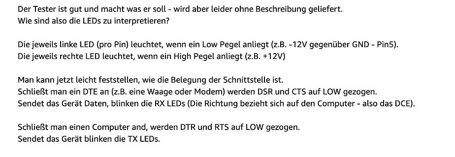
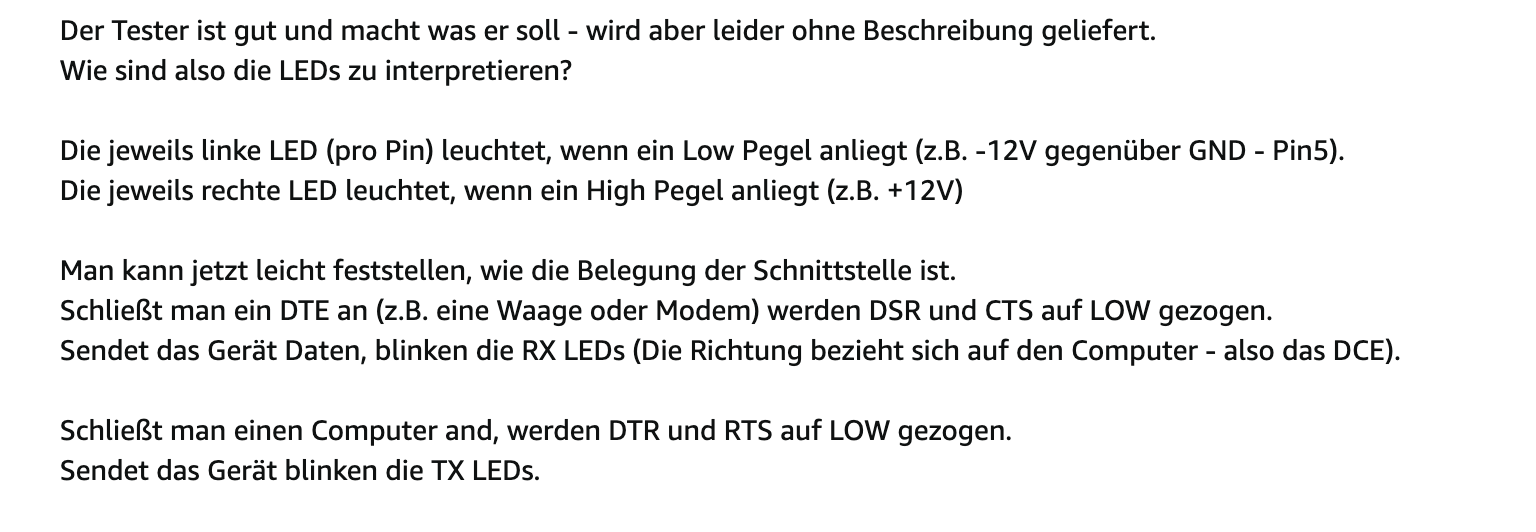
geliefert.
Wie sind also die LEDs zu interpretieren?
Die jeweils linke LED (pro Pin) leuchtet, wenn ein Low Pegel anliegt (z.B. -12V gegenüber GND - Pin5).
Die jeweils rechte LED leuchtet, wenn ein High Pegel anliegt (z.B. +12V)
Man kann jetzt leicht feststellen, wie die Belegung der Schnittstelle ist.
Schließt man ein DTE an (z.B. eine Waage oder Modem) werden DSR und CTS auf LOW gezogen.
Sendet das Gerät Daten, blinken die RX LEDs (Die Richtung bezieht sich auf den Computer - also das DCE).
Schließt man einen Computer and, werden DTR und RTS auf LOW gezogen.
Sendet das Gerät

 Bild
Bild
 Bild
Bild
 Bild
Bild
 Bild
Bild
 Bild
Bild
 Bild
Bild
 Bild
Bild
 Bild
Bild
 Bild
Bild
 Bild
Bild
 Bild
Bild