-
 Bild
Bild
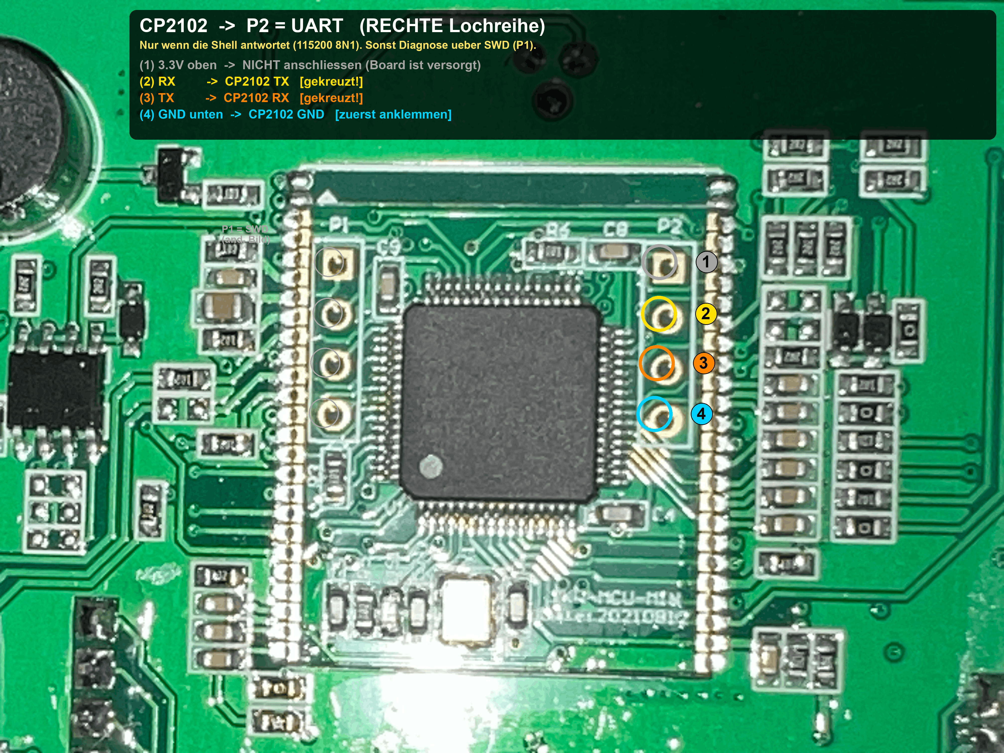
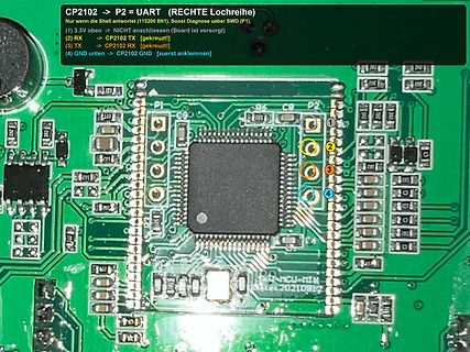
Leiterplatte mit Mikrocontroller und Pinbelegungshinweisen
CP2102 -> P2 = UART (RECHTE Lochreihe) Nur wenn die Shell antwortet (115200 BN1). Sonst Diagnose ueber SWD (P1). (2) RX -> CP2102 TX [gekreuzt] (3) TX -> CP2102 RX [gekreuzt] (4) GND unten -> CP2102 GND [
-
 Bild
Bild
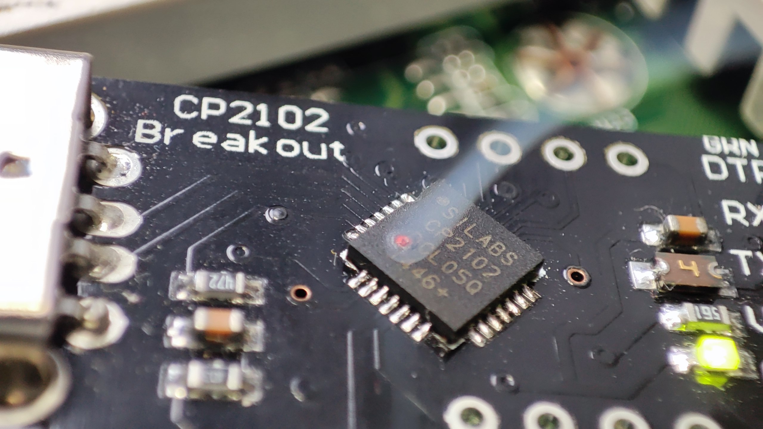
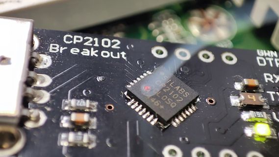
Nahaufnahme eines CP2102 Breakout Boards
CP2102 Breakout SILABS CP2102 46+ DTR RX TX
-
 Bild
Bild
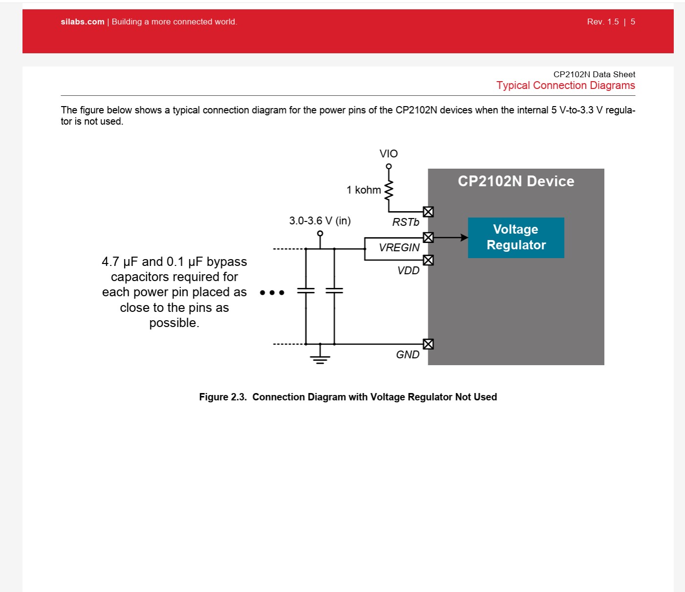
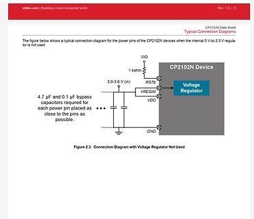
Verbindungsschema für CP2102N ohne internen Spannungsregler
silabs.com | Building a more connected world. Rev. 1.5 | 5 CP2102N Data Sheet Typical Connection Diagrams The figure below shows a typical connection diagram for the power pins of the CP2102N devices when the internal 5 V-to-3.3 V regulator is not used. VIO 1 kohm
-
 Bild
Bild
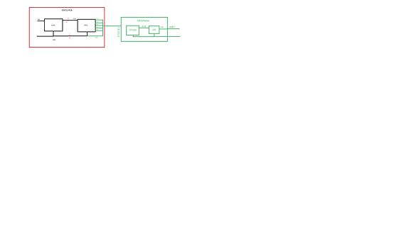
Blockschaltbild ESP32 PCB und ESP32flasher
ESP32 PCB 3.3V 3V3 EN IO0 IO1 IO3 GND ESP32 ESP32flasher CP2102 3.3V LDO USB-C
-
 Bild
Bild
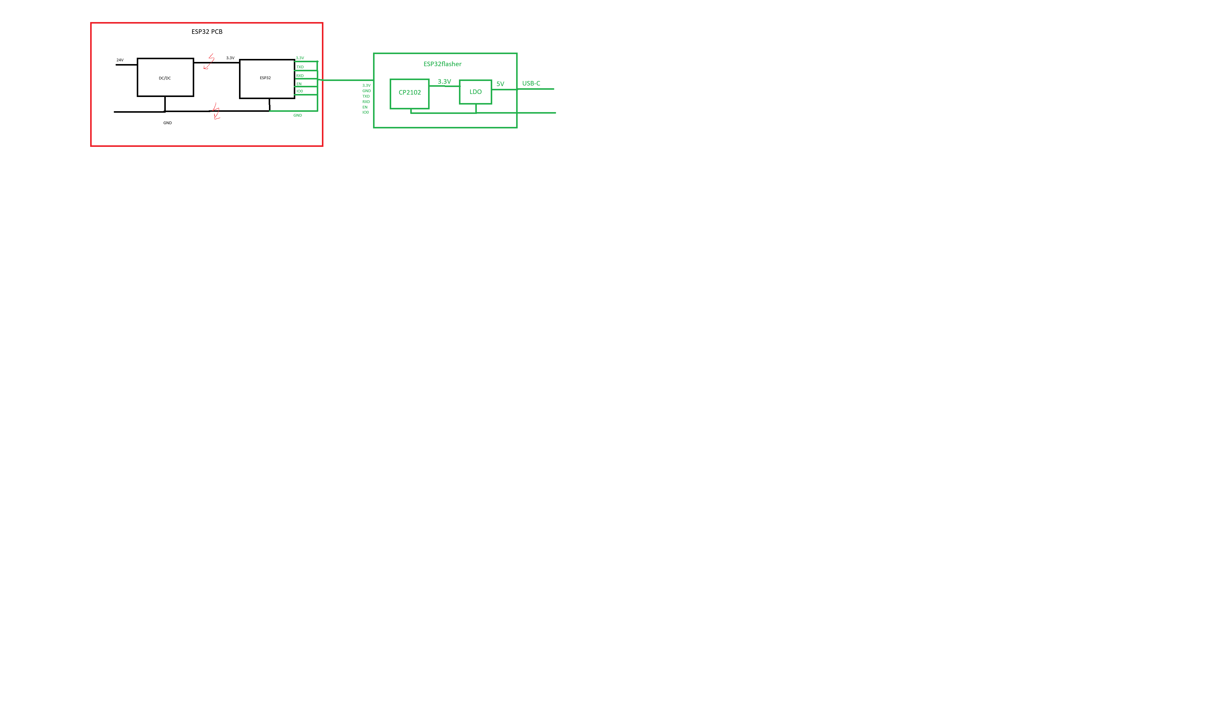
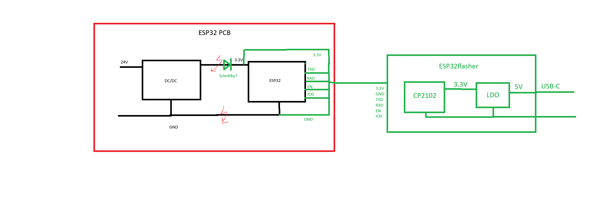
Blockschaltbild ESP32 PCB und ESP32flasher
ESP32 PCB 24V DC/DC Schottky? 3.3V ESP32 TXD RXD IO0 GND GND 3.3V ESP32flasher CP2102 3.3V LDO 5V USB-C GND TXD RXD EN IO0
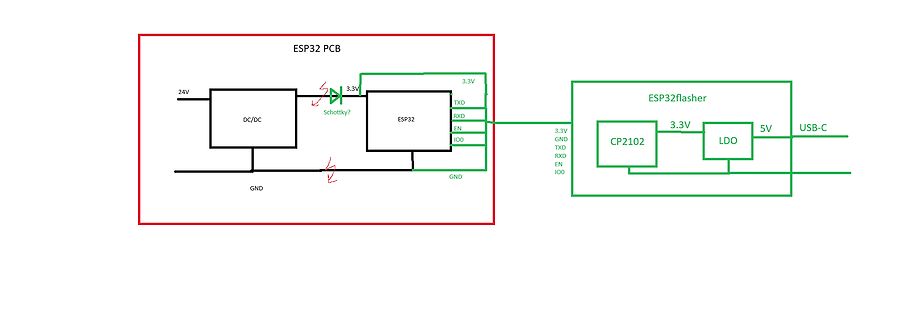
-
 Bild
Bild
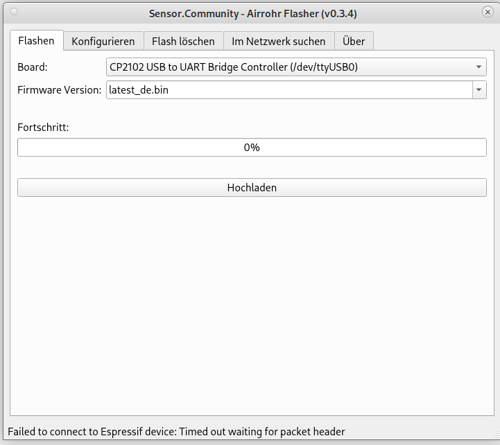
Screenshot eines Firmware-Flash-Tools mit Fehlermeldung
Sensor.Community - Airrhoh Flasher (v0.3.4) Flashen Konfigurieren Flash löschen Im Netzwerk suchen Über Board: CP2102 USB to UART Bridge Controller (/dev/ttyUSB0) Firmware Version: latest_de.bin Fortschritt: 0% Hochladen Failed to connect to Espressif device: Timed out waiting for packet header
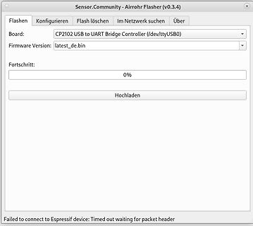
-
 Bild
Bild
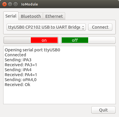
Screenshot einer Software zur seriellen Kommunikation
IoModule Serial Bluetooth Ethernet ttyUSB0 CP2102 USB to UART Bridge Connect on off Opening serial port ttyUSB0 Connected Sending: iPA3 Received: PA3=1 Sending: iPA4 Received: PA4=1 Sending: oPA4,0 Received: Ok Quit
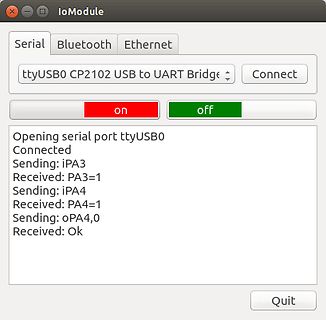
-
 Bild
Bild
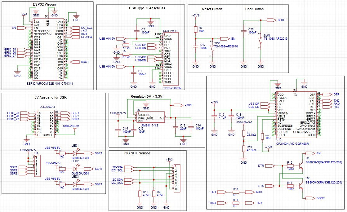
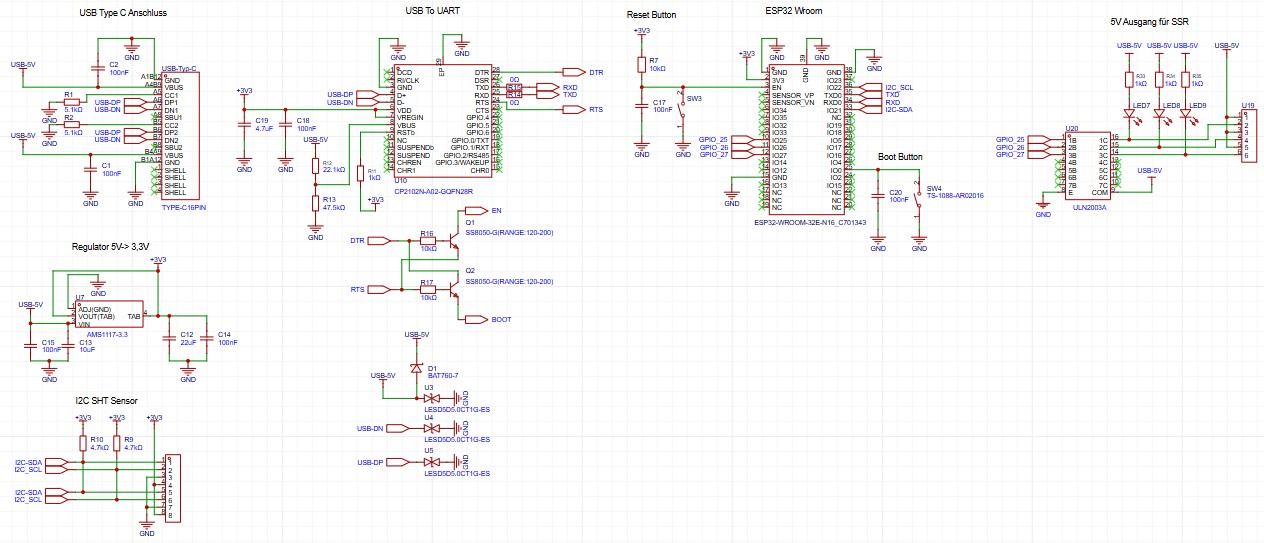
Schaltplan eines ESP32-basierten Systems mit Spannungsregler und Sensoren
Button, Boot Button, ULN2003A1, SSR1 bis SSR3, Regulator 5V -> 3,3V, AMS117-3.3, I2C SHT Sensor, CP2102N-A02-GQFZN2B8, SS8050-G(RANGE:120-200)
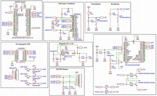
-
 Bild
Bild
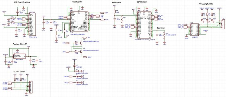
Schaltplan eines ESP32-Wroom-basierten Boards
Anschluss, USB To UART, Reset Button, ESP32 Wroom, 5V Ausgang SSR, Regulator 5V->3.3V, I2C SHT Sensor, CP2102N, AMS1117-3.3, SHT770-7, ULN2003A, LED1 bis LED4, USB-DN, USB-DP, GND, 3V3, 100nF, 4.7uF, 10k, 22k, 1k, 2.2k
-
 Bild
Bild
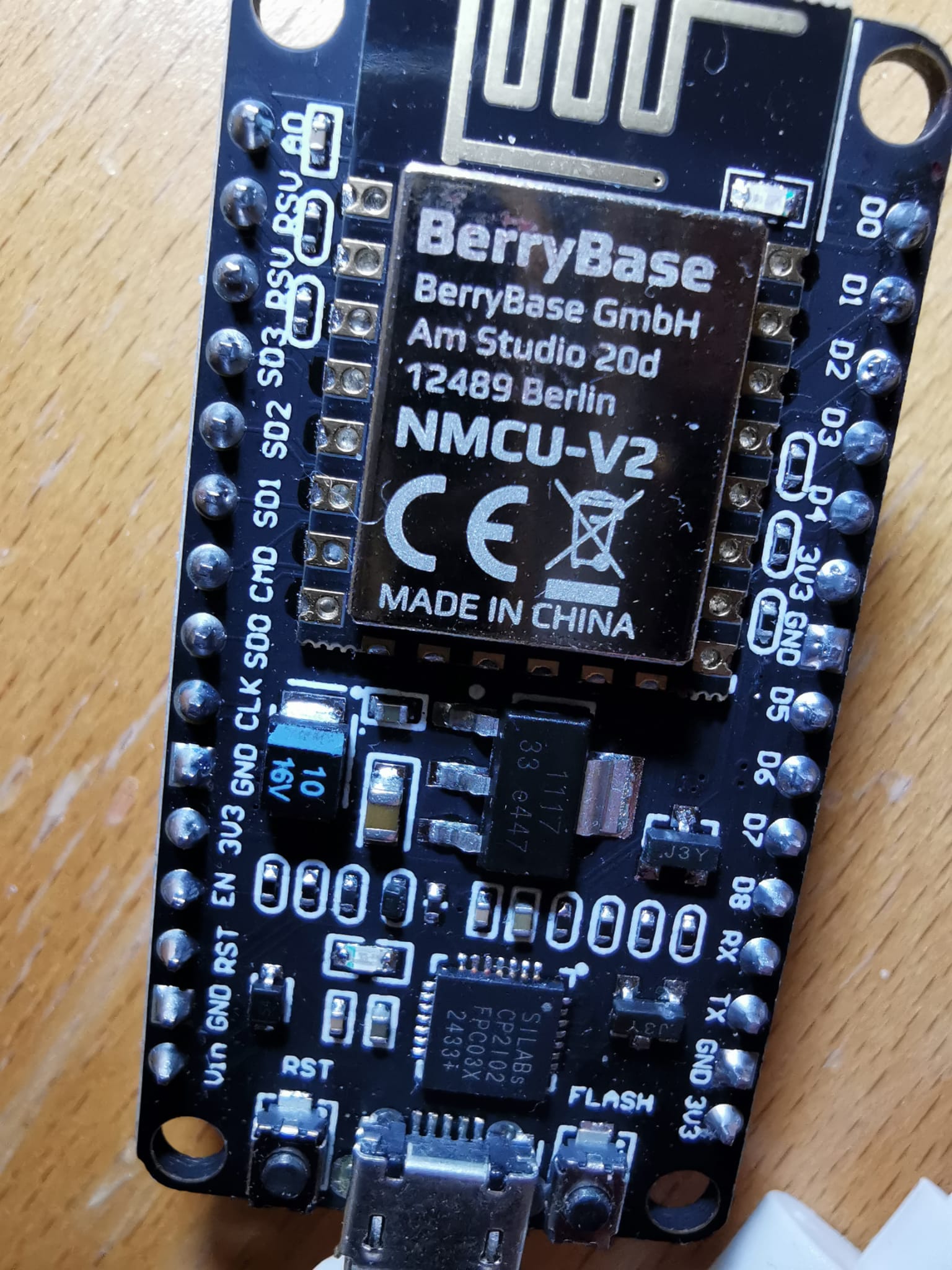
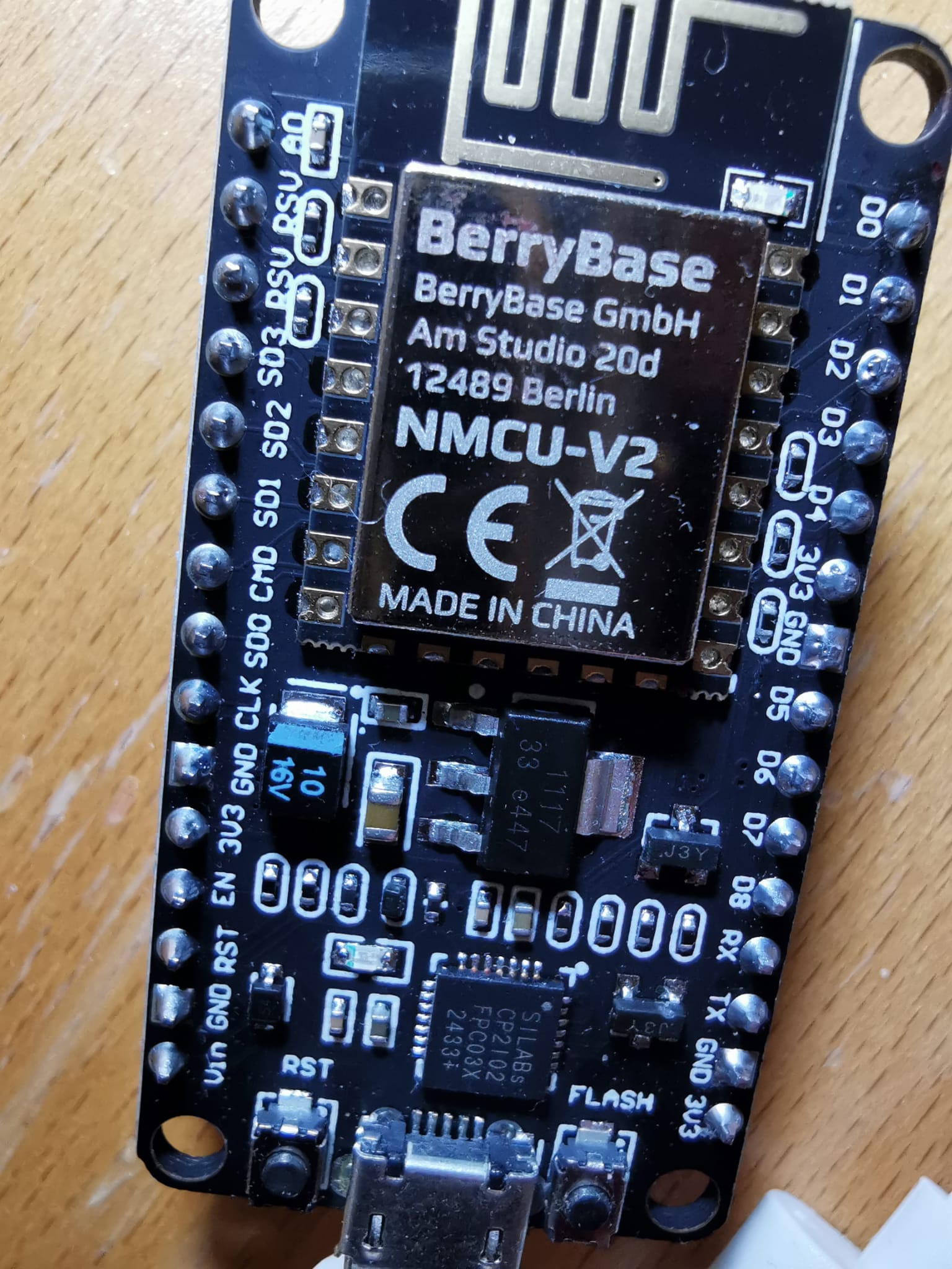
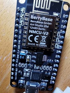
BerryBase NMCU-V2 Mikrocontroller-Modul
SD2 SD1 SD0 CLK GND 3V3 EN RST GND 3V3 GND D0 D1 D2 D3 D4 D5 D6 D7 D8 RX TX 10 1117 33 6447 SILABS CP2102 2433X RST FLASH 3V3 GND
-
 Bild
Bild
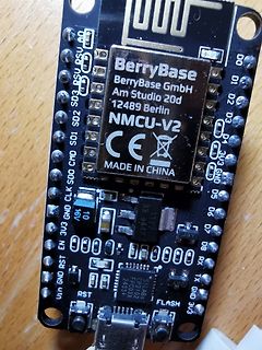
BerryBase NMCU-V2 Mikrocontroller-Modul
3V3 D0 D1 D2 D3 D4 3V3 GND 00 01 02 03 04 10 1117 33 6447 J3Y 08 RX TX GND 3V3 0000 00000 SILABS CP2102 2433X RST FLASH
-
 Bild
Bild
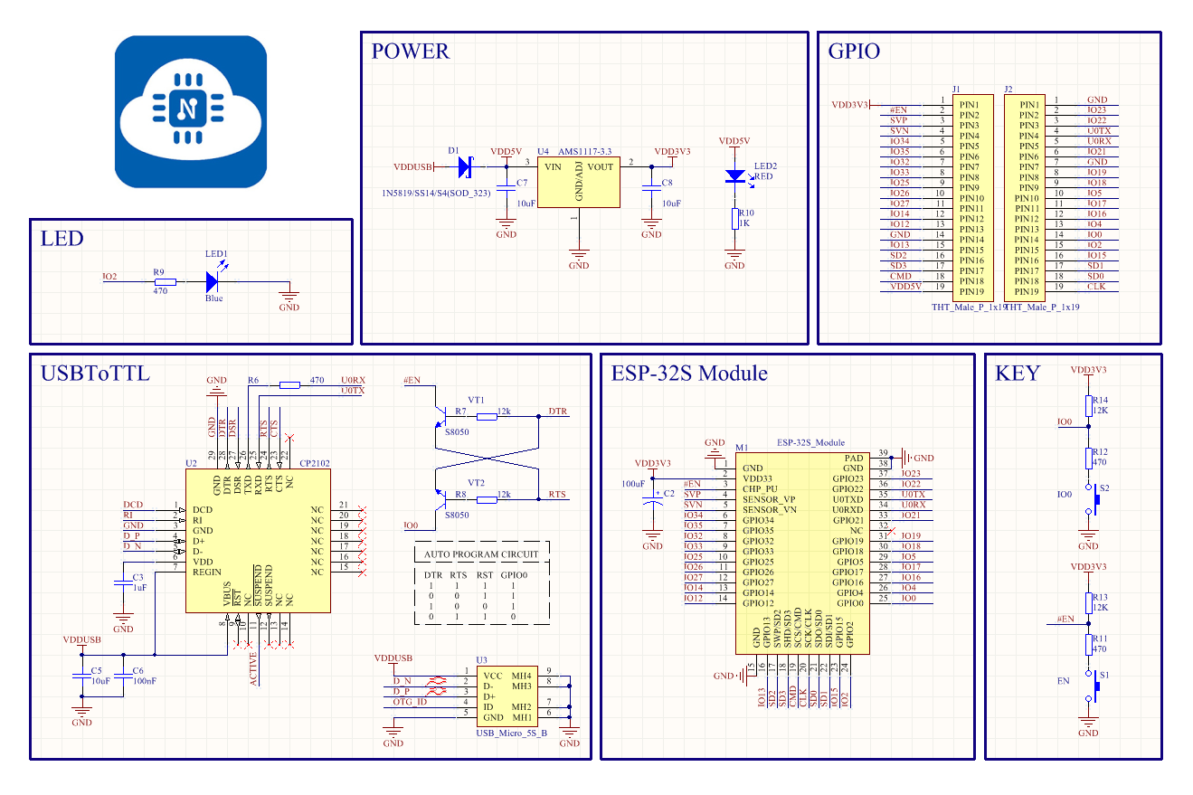
Schaltplan eines ESP-32S Moduls mit USB-zu-TTL Konverter
USBToTTL, ESP-32S Module, KEY, D1, VDD5V, VIN, VOUT, AMS1117-3.3, C7, 10uF, LED2 RED, R10, 1K, GND, U2, CP2102, DTR, RTS, TXD, RXD, DCD, RI, D+, D-, VDD, C3, 10uF, VDDUSB, C5, 100nF, C6, 100nF, U4, IO0, R7, 470, IO2, R9, 470, GPIO, IO35, IO34, IO32, IO33, IO25, IO26, IO27, IO12, IO13, IO14, IO15, IO16, IO17