-
 Bild
Bild
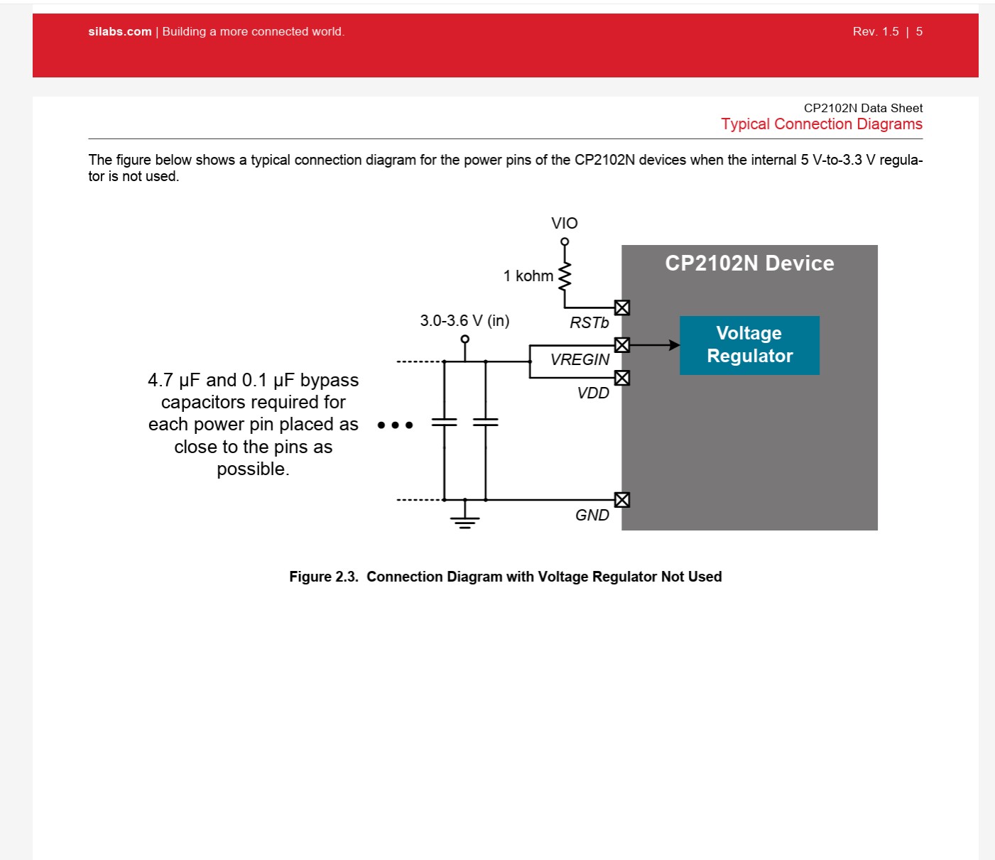
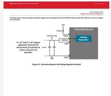
Verbindungsschema für CP2102N ohne internen Spannungsregler
silabs.com | Building a more connected world. Rev. 1.5 | 5 CP2102N Data Sheet Typical Connection Diagrams The figure below shows a typical connection diagram for the power pins of the CP2102N devices when the internal 5 V-to-3.3 V regulator is not used. VIO 1 kohm
-
 Bild
Bild
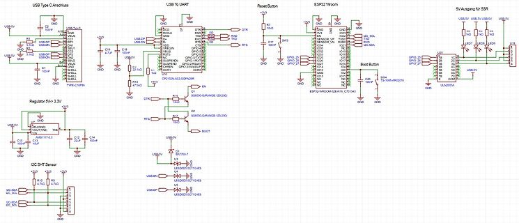
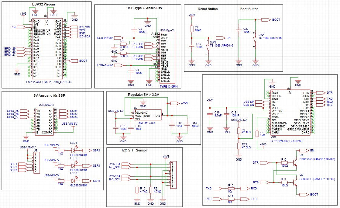
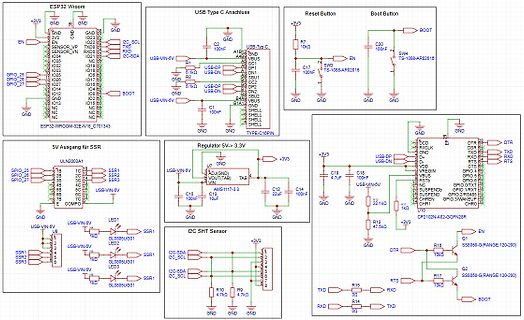
Schaltplan eines ESP32-basierten Systems mit Spannungsregler und Sensoren
Button, Boot Button, ULN2003A1, SSR1 bis SSR3, Regulator 5V -> 3,3V, AMS117-3.3, I2C SHT Sensor, CP2102N-A02-GQFZN2B8, SS8050-G(RANGE:120-200)
-
 Bild
Bild
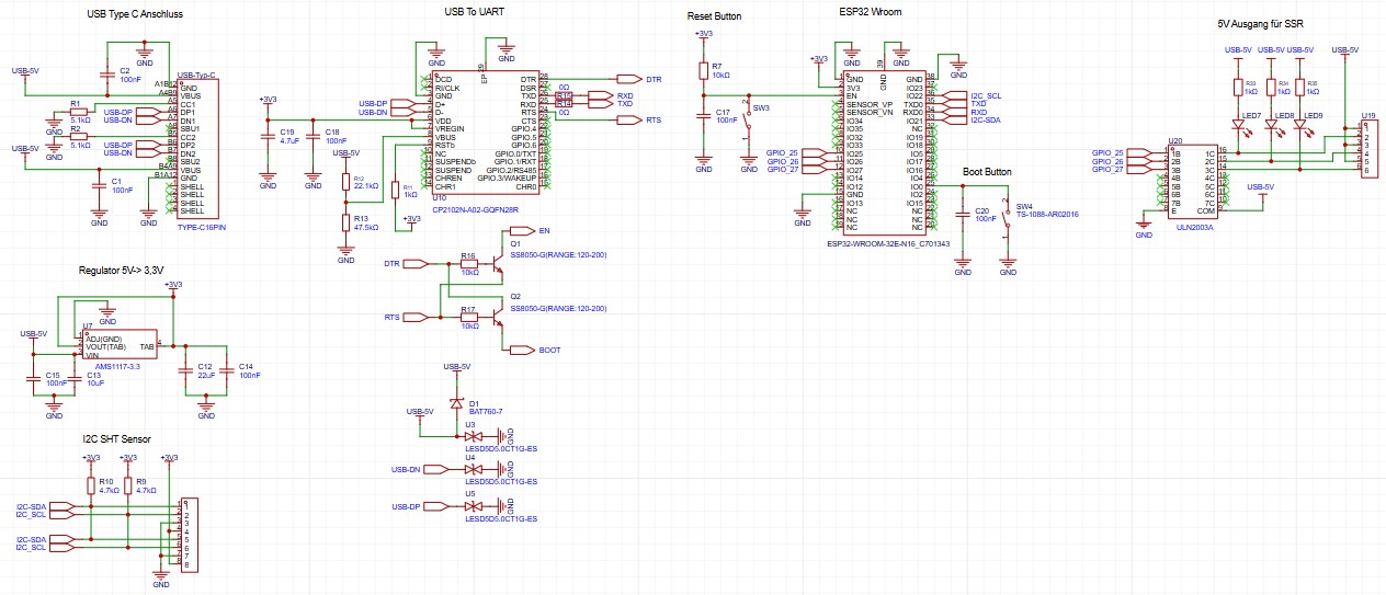
Schaltplan eines ESP32-Wroom-basierten Boards
Anschluss, USB To UART, Reset Button, ESP32 Wroom, 5V Ausgang SSR, Regulator 5V->3.3V, I2C SHT Sensor, CP2102N, AMS1117-3.3, SHT770-7, ULN2003A, LED1 bis LED4, USB-DN, USB-DP, GND, 3V3, 100nF, 4.7uF, 10k, 22k, 1k, 2.2k