-
Bild
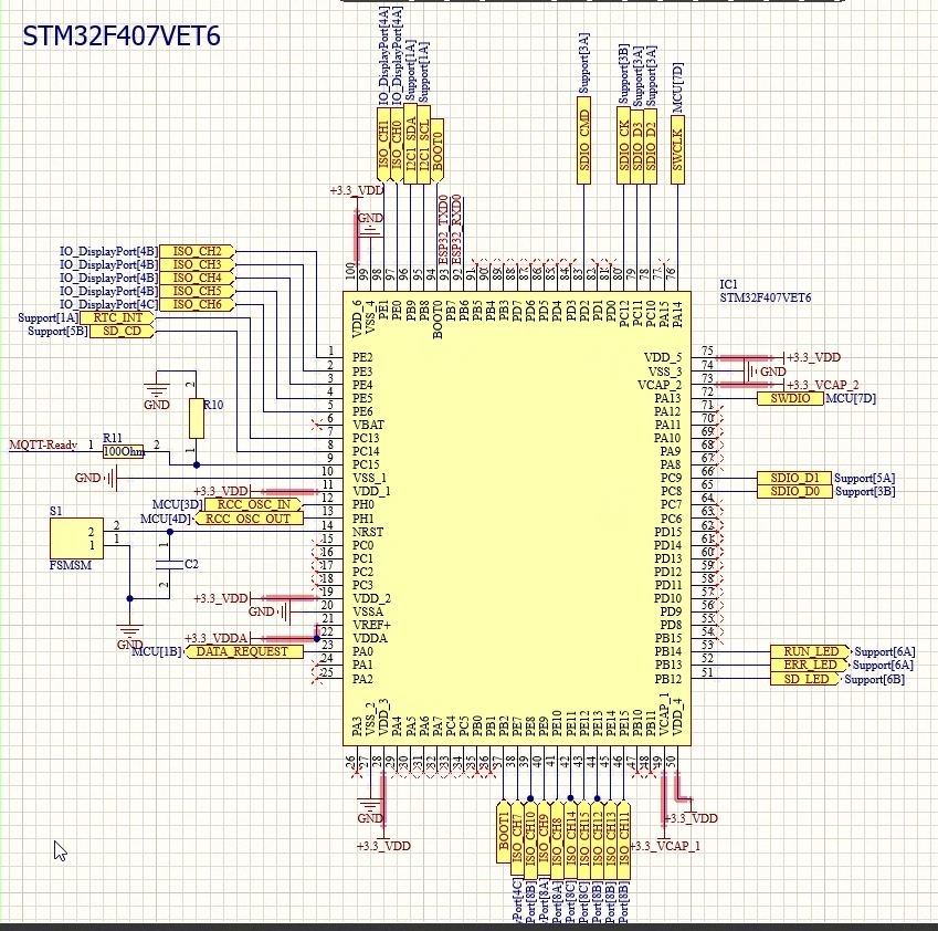
Schaltplan eines STM32F407VET6 Mikrocontrollers
STM32F407VET6, IO_DisplayPort[4A], IO_DisplayPort[4B], Support[1A], Support[5B], SD_CD, R11 100Ohm, MCU[4D] RCC OSC IN, MCU[4D] RCC OSC OUT, MCU[1B] DATA REQUEST, SD LED Support[6A], RUN LED Support[6A], ERR
in „STM32F4 zieht zu viel Strom“ · Mikrocontroller und Digitale Elektronik · · Schaltpläne
-
Datei
main.c
define TIM_PERIOD 5 # else # error STM32 unknown # endif #elif defined (BLACK_BOARD) # if defined (STM32F407VE) // STM32F407VE Black Board @168MHz # define TIM_CLK 84000000L // APB2 clock: 84 MHz # define TIM_PERIOD 7 # else # error STM32 unknown # endif #elif defined (BLACKPILL_BOARD) # if defined (STM32F401CC
-
Bild
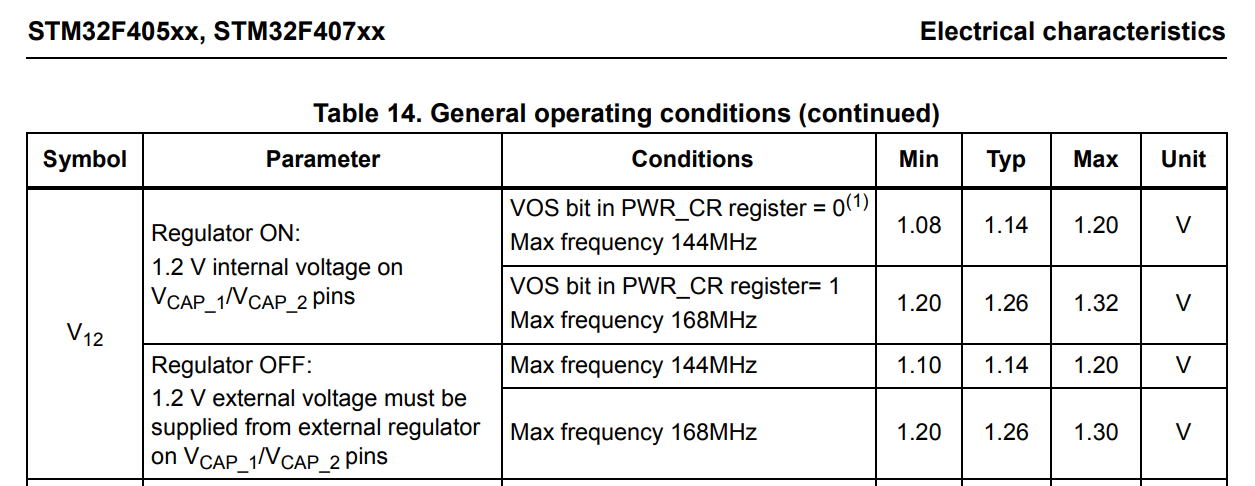
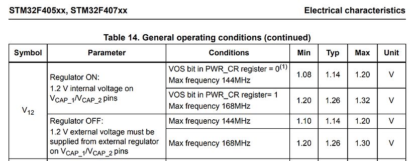
Tabelle der elektrischen Charakteristiken eines STM32F405xx Mikrocontrollers
STM32F405xx, STM32F407xx Electrical characteristics Table 14. General operating conditions (continued) Symbol Parameter Conditions Min Typ Max Unit V12 Regulator ON: 1.2 V internal voltage on VCAP_1/VCAP_2 pins VOS bit
in „STM32F4 zieht zu viel Strom“ · Mikrocontroller und Digitale Elektronik · · Screenshots
-
Datei
HD66766_example.c
/ LCD Driver IC: Hitachi HD66766 // IM0=Low, IM1=High, 16-bit interface, 80-mcu-family // MCU: STM32 F407 VET6 // ========================================================(C) 2/2026 Ma_Baker============= // ======================================================================================== // Disclaimer
in „LCD-Modul F51661GNCJU-MLW-AA * Info *“ · Mikrocontroller und Digitale Elektronik ·
-
Datei
session1.txt
Möchtest du, dass ich auch die spezifischen Clock-Konfigurationen für ein bestimmtes Board (z.B. STM32F407 Nucleo) genauer erkläre? >>> ja, bitte erkläre die clock-settings Thinking... Thinking Process: 1. **Analyze the Request:** * User wants an explanation of the clock settings (clock configuration)