-
 Bild
Bild
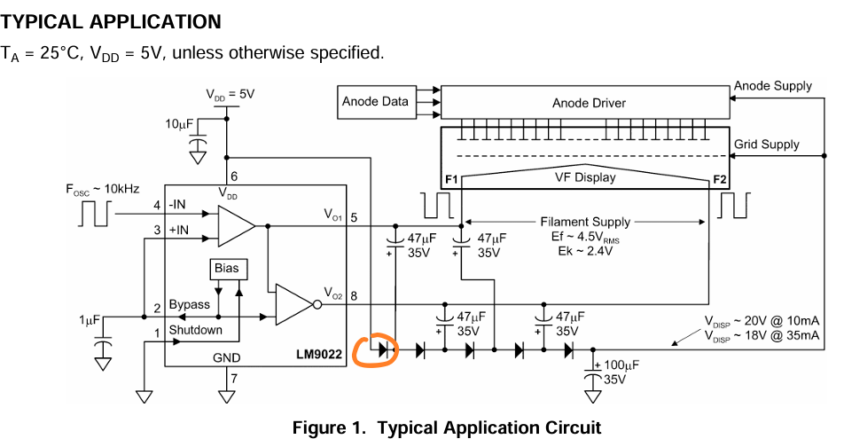
Schaltplan einer typischen Anwendung mit LM9022
Anode Driver Grid Supply VF Display F1 F2 FOSC ~ 10kHz VDD = 5V 10µF 6 4 -IN 3 +IN 2 Bypass 1 Shutdown LM9022 7 GND VO1 5 VO2 8 Bias 47µF 35V 47µF 35V 47µF 35V 47µF 35V 1µF Filament Supply Ef ~ 4.5VRMS Ek ~ 2.4V 100µF 35V VDISP ~ 20V @ 10mA VDISP ~ 18V @ 35mA Figure 1. Typical Application Circuit

-
 Bild
Bild
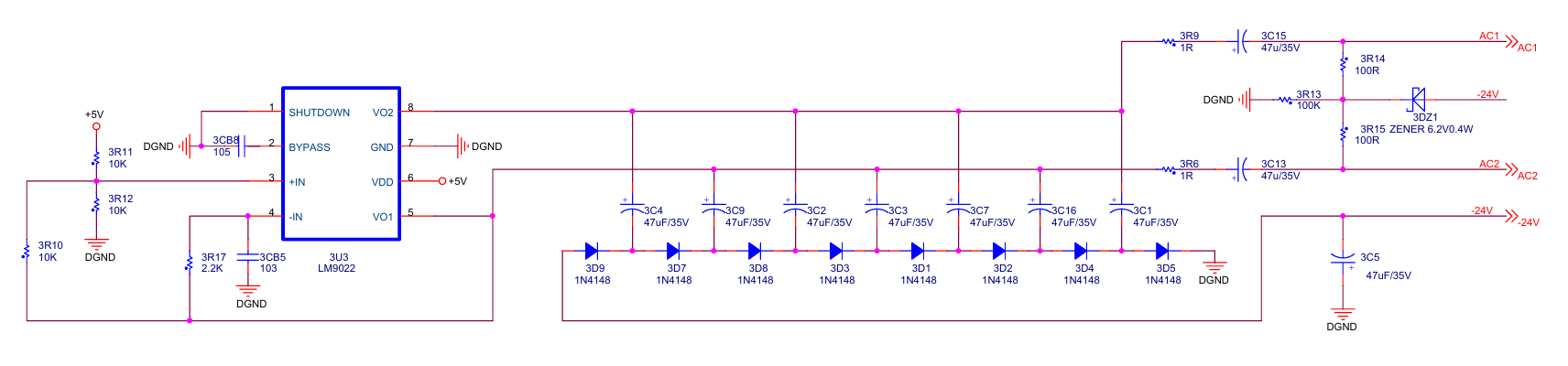
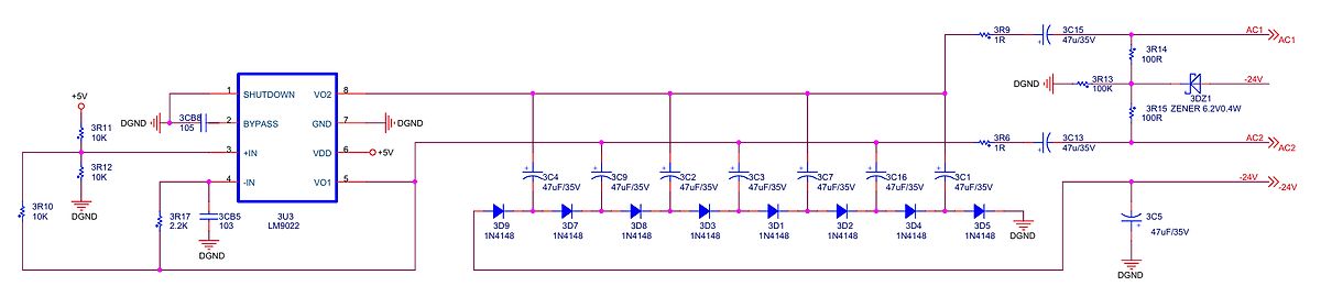
Schaltplan eines Gleichrichters mit LM9022 Spannungsregler
3R12 10K 2 BYPASS 3R13 100K DGND 3DZ1 ZENER 6.2V 0.4W 3R15 100R AC2 -24V 3 3IN 4 VDD 5 VO1 -IN 3U3 LM9022 3R17 2.2K 3CB5 103 3D9 1N4148 3D7 1N4148 3D8 1N4148 3D3 1N4148 3D1 1N4148 3D2 1N4148 3D4 1N4148 3D5 1N4148 DGND 3C4 47uF/35V 3C9 47uF/35V 3C2 47uF/35V 3C3 47uF/35V 3C7 47uF/35V 3C16 47uF/35V 3C1
-
 Bild
Bild
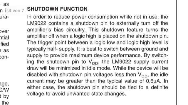
Ausschnitt aus einem Datenblatt zur Shutdown-Funktion
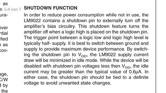
SHUTDOWN FUNCTION In order to reduce power consumption while not in use, the LM9022 contains a shutdown pin to externally turn off the amplifier's bias circuitry. This shutdown feature turns the amplifier off when a logic high is placed on the shutdown pin. The trigger point between