-
Datei
uart.h
circular receive buffer, must be power of 2 */ #ifndef UART_RX_BUFFER_SIZE #define UART_RX_BUFFER_SIZE 32 #endif /** Size of the circular transmit buffer, must be power of 2 */ #ifndef UART_TX_BUFFER_SIZE #define UART_TX_BUFFER_SIZE 32 #endif /* test if the size of the circular buffers fits into SRAM */
in „[AVR-GCC] makefile SRC und #include“ · Mikrocontroller und Digitale Elektronik ·
-
Datei
uart.h
circular receive buffer, must be power of 2 */ #ifndef UART_RX_BUFFER_SIZE #define UART_RX_BUFFER_SIZE 32 #endif /** Size of the circular transmit buffer, must be power of 2 */ #ifndef UART_TX_BUFFER_SIZE #define UART_TX_BUFFER_SIZE 32 #endif /* test if the size of the circular buffers fits into SRAM */
in „ATmega168 Bootloader“ · Mikrocontroller und Digitale Elektronik ·
-
Datei
uart.h
circular receive buffer, must be power of 2 */ #ifndef UART_RX_BUFFER_SIZE #define UART_RX_BUFFER_SIZE 32 #endif /** Size of the circular transmit buffer, must be power of 2 */ #ifndef UART_TX_BUFFER_SIZE #define UART_TX_BUFFER_SIZE 32 #endif /* test if the size of the circular buffers fits into SRAM */
in „fleurys I2C + UART lib halten in Kombination die Hauptschleife an!“ · Mikrocontroller und Digitale Elektronik ·
-
Datei
uart.h
circular receive buffer, must be power of 2 */ #ifndef UART_RX_BUFFER_SIZE #define UART_RX_BUFFER_SIZE 32 #endif /** Size of the circular transmit buffer, must be power of 2 */ #ifndef UART_TX_BUFFER_SIZE #define UART_TX_BUFFER_SIZE 32 #endif /* test if the size of the circular buffers fits into SRAM */
in „RFM70 Timing Problem?“ · Mikrocontroller und Digitale Elektronik ·
-
Datei
uart.h
circular receive buffer, must be power of 2 */ #ifndef UART_RX_BUFFER_SIZE #define UART_RX_BUFFER_SIZE 32 #endif /** Size of the circular transmit buffer, must be power of 2 */ #ifndef UART_TX_BUFFER_SIZE #define UART_TX_BUFFER_SIZE 32 #endif /* test if the size of the circular buffers fits into SRAM */
in „UART Auswertung“ · Mikrocontroller und Digitale Elektronik ·
-
Datei
uart.h
circular receive buffer, must be power of 2 */ #ifndef UART_RX_BUFFER_SIZE #define UART_RX_BUFFER_SIZE 32 #endif /** Size of the circular transmit buffer, must be power of 2 */ #ifndef UART_TX_BUFFER_SIZE #define UART_TX_BUFFER_SIZE 32 #endif /* test if the size of the circular buffers fits into SRAM */
in „µC rechnet falsch oder ich finde den Fehler nicht“ · Mikrocontroller und Digitale Elektronik ·
-
Datei
uart.h
circular receive buffer, must be power of 2 */ #ifndef UART_RX_BUFFER_SIZE #define UART_RX_BUFFER_SIZE 32 #endif /** Size of the circular transmit buffer, must be power of 2 */ #ifndef UART_TX_BUFFER_SIZE #define UART_TX_BUFFER_SIZE 32 #endif /* test if the size of the circular buffers fits into SRAM */
in „µC rechnet falsch oder ich finde den Fehler nicht“ · Mikrocontroller und Digitale Elektronik ·
-
Datei
uart.h
circular receive buffer, must be power of 2 */ #ifndef UART_RX_BUFFER_SIZE #define UART_RX_BUFFER_SIZE 32 #endif /** Size of the circular transmit buffer, must be power of 2 */ #ifndef UART_TX_BUFFER_SIZE #define UART_TX_BUFFER_SIZE 32 #endif /* test if the size of the circular buffers fits into SRAM */
in „ATmega UART spinnt“ · Mikrocontroller und Digitale Elektronik ·
-
Datei
uart.h
circular receive buffer, must be power of 2 */ #ifndef UART_RX_BUFFER_SIZE #define UART_RX_BUFFER_SIZE 32 #endif /** Size of the circular transmit buffer, must be power of 2 */ #ifndef UART_TX_BUFFER_SIZE #define UART_TX_BUFFER_SIZE 32 #endif /* test if the size of the circular buffers fits into SRAM */
in „avr dude Programm zu groß? Eclipse GCC“ · Mikrocontroller und Digitale Elektronik ·
-
Datei
uart.h
circular receive buffer, must be power of 2 */ #ifndef UART_RX_BUFFER_SIZE #define UART_RX_BUFFER_SIZE 32 #endif /** Size of the circular transmit buffer, must be power of 2 */ #ifndef UART_TX_BUFFER_SIZE #define UART_TX_BUFFER_SIZE 32 #endif /* test if the size of the circular buffers fits into SRAM */
in „UART mit Atmega8 (Peter Fleury Library)“ · Mikrocontroller und Digitale Elektronik ·
-
Datei
uart.h
circular receive buffer, must be power of 2 */ #ifndef UART_RX_BUFFER_SIZE #define UART_RX_BUFFER_SIZE 32 #endif /** Size of the circular transmit buffer, must be power of 2 */ #ifndef UART_TX_BUFFER_SIZE #define UART_TX_BUFFER_SIZE 32 #endif /* test if the size of the circular buffers fits into SRAM */
in „AVR bootloader Probleme“ · Mikrocontroller und Digitale Elektronik ·
-
Datei
uart.h
circular receive buffer, must be power of 2 */ #ifndef UART_RX_BUFFER_SIZE #define UART_RX_BUFFER_SIZE 32 #endif /** Size of the circular transmit buffer, must be power of 2 */ #ifndef UART_TX_BUFFER_SIZE #define UART_TX_BUFFER_SIZE 32 #endif /* test if the size of the circular buffers fits into SRAM */
in „UART Bibliothek funktioniert nicht“ · Mikrocontroller und Digitale Elektronik ·
-
Datei
uart.h
circular receive buffer, must be power of 2 */ #ifndef UART_RX_BUFFER_SIZE #define UART_RX_BUFFER_SIZE 32 #endif /** Size of the circular transmit buffer, must be power of 2 */ #ifndef UART_TX_BUFFER_SIZE #define UART_TX_BUFFER_SIZE 32 #endif /* test if the size of the circular buffers fits into SRAM */
in „AVR Bootloader in C - Artikel“ · Mikrocontroller und Digitale Elektronik ·
-
Datei
main_sender.c
interrupt.h> #include <util/delay.h> #include "wl_module.h" #include "nRF24L01.h" #include "spi.h" void atmega_init(); void uart_init(void); int uart_putuint8_1(uint8_t c); void uart_putuint8_s(uint8_t *s); int uart_putc(char c); void uart_puts (char *s); uint8_t sendedaten[wl_module_PAYLOAD] = "Dies sind 32
in „NRF24L01 und Atmega328P“ · Mikrocontroller und Digitale Elektronik ·
-
PDF
Umweltdaten.pdf
1 2 3 4 5 6 Ureg ATmega328 connector A A O.S._1 PD2 O.S._2 PD3 O.S._3 PD4 ureg.sch atmega328.sch con.sch B B GY88 microSD PD5 G_INT M_DRDY PD6 C C gy88.sch microsd.sch D Sheet: / D File: Umweltdaten.sch Title: Size: A4 Date
in „Schaltplan prüfen“ · Platinen ·
-
Datei
graphic2.c
Datum: 30.08.2004 Zweck: Test des Panels benötigte Software: AVR-GCC benötigte Hardware: LED Panel, ATMEGA8;ATMEGA32 oder ähnlichen mit 8MHZ Note: Wer Fragen oder Anregungen zu dem Programm hat, kann an m.marwedel <AT> onlinehome.de mailen. Mehr über Elektronik und AVRs gibt es auf meiner Homepage: http
in „Optimierung mittels typecast“ · Mikrocontroller und Digitale Elektronik ·
-
Datei
main.c
****** Timer 0 ****************************** // TCCR0 = (1<<CS02)|(1<<CS00); // divide by 1024 (ATMEGA8) TCCR0B = (1<<CS02); // divide by 256 (ATMEGA168 bei 4Mhz Quarz) TCNT0 = (uint8_t)(int16_t)-(F_CPU / 256 * 64); // preload for 10ms // TIMSK |= 1<<TOIE0; // enable timer interrupt (ATMEGA8) TIMSK0
in „Unabhängiger Timer gesucht“ · Mikrocontroller und Digitale Elektronik ·
-
Datei
Addon-Test.bas
der Möglichkeit eines solchen Schadens unterrichtet worden ist. ' 'Testprogramm fuer ATTiny2313, ATMega8, ATMega16, ATMega32, 'ATMEL Evaluations-Board Best.Nr. 810 038 und 'ATMEL Addon-Board V1.0 Best.Nr. 810 053 '*************************************************************************************** $regfile = "m32def.dat" 'Taktfrequenz 1MHz $crystal = 1000000 'Baudrate für UART $baud = 2400 #if _chip = 0 'Tiny 2313 Lcd_db4 Alias Portb.2 Lcd_db5 Alias Portb.3 Lcd_db6 Alias Portb.4 Lcd_db7 Alias Portb.5 Lcd_e Alias
in „Pollin AddOnBoard.ist LCD defekt?“ · Mikrocontroller und Digitale Elektronik ·
-
PDF
crumb_128.pdf
100n 4k7 GND 5 C7 1 100n U2 C8 CON1 U1 CON2 16 2 100n 1 64 12 /FORCEOFF C C1+ 4 1 RXD0 2 /PEN AVCC 63 32 FORCEON V C1- 5 100n 2 TXD0 3 RXD0 (PDI) PE0 GND 62 31 1 C2+ 6 3 TXD0 PDO PE1 AREF 30 CON4 /EN C2- 4 4 XCK0 AIN0 PE2 PF0 ADC0 61 29 V+ 3 R7 5 5 OC3A AIN1 PE3 PF1 ADC1 60 28 5 10 /INVALID V- 7 TXD0 6
in „Crumb128 Probleme bei der Inbetriebnahme“ · Mikrocontroller und Digitale Elektronik ·
-
PDF
nRF24L01plus.pdf
2.4GHz-HowTo von der Beschreibung abweichend sind die folgenden Verbindungen: • nRF24L01+ CE → Arduino D8 (ATMega8 PB0) • nRF24L01+ CSN → Arduino D4 (ATMega8 PD4) • nRF24L01+ IRQ → Arduino D3 (ATMega8 PD3) Gaaaanz wichtig der 100µF Kondensator nahe bei der 3,3V Versorgung für den nRF24L01+ nicht vergessen. Die
in „Repeating und Routing Netzwerk mit Arduino und nRF24L01+“ · Projekte & Code ·
-
PDF
AppNote_Atmel_RTC.pdf
intervals. Figure 2-1. Oscillator Connection for Real Time Clock XTAL1 4.000 MHz R XTAL2 V CC AVR ATmega103 TOSC2 TIMER/COUNTER0 32.768 kHz TOSC1 Because of the amount time for the Timer/Counter to complete one overflow is always the same, each of these timer variables will be incremented by a fixed number
in „Atmel AVR Controller mit integrierter RTC“ · Mikrocontroller und Digitale Elektronik ·
-
PDF
Atmega_16_tea5767_c.pdf
...Atmega 16 tea5767\Atmega 16 tea5767\Atmega 16 tea5767.c 1 /** FM radio Built with WinAVR 20090313, avr-libc 1.6.6 User interface: pushbuttons at PD2 and PD3 (connected to the GND), used internal pull-ups.
in „PORT B LCD Atmega“ · Mikrocontroller und Digitale Elektronik ·
-
PDF
ZigBit_OEM_Module_Product_Datasheet.pdf
regions where the directive is enforced July 1, 2006. VCC (1.8 – 3.6V) The ZigBit contains Atmel’s ATmega1281V Microcontroller[1] and AT86RF230 RF Transceiver [2]. The module features 128kb flash memory and 8 kb RAM. The ZigBit already contains a complete RF/MCU-related IRQ UART ATmega1281 design with
-
Datei
optiboot_atmega128.lst
|(TWO_STOP_BITS<<USBS0)|(1<<UCSZ01)|(1<<UCSZ00) ;config UART U8N2 AOUT UART_SRC, r23 #else /* no ATmega8_16_32 */ #if !defined(__AVR_ATmega163__) && !defined(__AVR_ATtiny87__) && !defined(__AVR_ATtiny167__) ldi r23, (TWO_STOP_BITS<<USBS0)|(1<<UCSZ00)|(1<<UCSZ01) ;config UART U8N2 1fc4a: 7e e0 ldi r23
in „Tester für Spezialversion des AVR Bootloaders optiboot gesucht!“ · Mikrocontroller und Digitale Elektronik ·
-
PDF
Umweltdaten.pdf
1 2 3 4 5 6 Ureg ATmega328 connector A A O.S._1 PD2 O.S._2 PD3 O.S._3 PD4 ureg.sch atmega328.sch con.sch B B GY88 microSD PD5 G_INT M_DRDY PD6 C C gy88.sch microsd.sch D Sheet: / D File: Umweltdaten.sch Title: Size: A4 Date
in „Schaltplan prüfen“ · Platinen ·
-
Datei
Handschalter.bas
funktionfähig '----------------------------------------------------------- ' Grundeinstellungen ATMEGA128 $regfile = "m128def.dat" 'ATMega128 definieren $crystal = 16000000 'Taktfrequenz auf 6 MHz setzen $baud = 19200 'Baudrate für Diagnose $hwstack = 128 ' default use 32 for the hardware stack $swstack
in „3.5" TFT-Display an Atmega128“ · Mikrocontroller und Digitale Elektronik ·
-
PDF
_Dokumentation_V1.0_Stand_22.03.2012.pdf
für Säule 9 bis 16 ans zweite Latch u.s.w. bis alle 13 Latches gefüllt sind. Die Ebenen werden ja ATMega32 eigentlich durch die Mosfets geschaltet. µC Pinbenutzung: 8 x Datenleitungen für Bitmuster zu den Latches 13 x Latch Enabled 10 x Ebenensteuerung der Mosfets ---------------------------------------------- 31 Pins werden benötigt….bis jetzt… Nun hat ein ATMega 32 ja nur 40 IO-Pins…und ich hatte mir im Hinterkopf behalten, die Muster mal auf eine SD-Karte zu speichern und sie von dort aus anzeigen zu lassen. 5 Das 13te Latch ist nur bis zur Hälfte gefüllt
in „Tutorial 10x10x10 LED-Cube“ · Mikrocontroller und Digitale Elektronik ·
-
PDF
Bauteile.pdf
TPS79030DBVT LDO 10V 3,0V 50mA 7 595-TPS79030DBVT 1,97 € MSP430F2252TRHAT MCU 1 595-MSP430F2252TRHAT ATMEGA328P-AU Microkontroller TQFP-32 2 556-ATMEGA328P-AU 2,78 € STM32F051R8T6 Mikrocontroller LQFP-64 1 511-STM32F051R8T6 5,64 € GD32F405RGT6 Mikrocontroller LQFP-64 5 LCSC 7,96 € STM32F405RGT6 Mikrocontroller LQFP-64 5 511-STM32F405RGT6 15,84 € TK4R4P06PL,RQ Mosfet N-Ch 60V 3.4mR DPAK 7 757-TK4R4P06PLRQ 1,51 € IRFR8314 Mosfet N-Ch 30V 2.2mR DPAK 4 942-IRFR8314TRPBF 1,93 € ADG884BRMZ Muxer Analog switch 5 584-ADG884BRMZ 3,46
in „[V] diverse Bauteile“ · Markt ·
-
Datei
uart.h
// Puffergroesse für den Ringpuffer !!!Ringpuffer muss immer der Groesse 2^n entsprechen (2,4,8,16,32...)!!! #define PufferGroesse 32 // Test ob der Ringpuffer in den SRAM passt #if ( (PufferGroesse+PufferGroesse) >= (RAMEND-0x60 ) ) #error "Groesse von Rx und Tx Puffer groesser als SRAM Spec" #endif
in „TTL Signal Verarbeitung“ · Mikrocontroller und Digitale Elektronik ·
-
Datei
build_failed.txt
funsigned-char -funsigned-bitfields -O0 -fpack-struct -fshort-enums -g2 -Wall -c -std=gnu99 -mmcu=atmega32 -MD -MP -MF"GLCD_KS0108.d" -MT"GLCD_KS0108.d" -o"GLCD_KS0108.o" ".././GLCD_KS0108.c" .././GLCD_KS0108.c: In function 'main': C:\temp\GLCD_KS0108\GLCD_KS0108\GLCD_KS0108.c(28,2): pointer targets in
in „GLCD KS0108 und apetech lib aus dem Wiki“ · Mikrocontroller und Digitale Elektronik ·
-
PDF
TransistorTester_eng_094k.pdf
display layout is changed from hFE= to B= to save space. 11. The differences of reference voltage ofATmega8,ATmega88,ATmega168 andATmega328 are applied as noted in the data sheet. You can also use the feature WITH_AUTO_REF with a Makefile option, in this case the reference Voltage is read out withADC. The
-
Datei
ledmatrix4.c
Datum: 16.08.2004 Zweck: Test des Panels benötigte Software: AVR-GCC benötigte Hardware: LED Panel, ATMEGA8 oder ähnlichen Note: Erfolgreich getestet wurde das Programm mit einem ATMEGA8 (1MHZ, 4MHZ, 8MHZ). Der Test mit einem AT90S4433 (8MHZ) schlug fehl, ich habe zwei verschiendene AT90S4433 ausprobiert
in „Programm läuft mit ATMEGA8, nicht jedoch mit AT90S4433“ · Mikrocontroller und Digitale Elektronik ·
-
Datei
small_printf.c
von ATmegaxx8 anpassen -------------------------------------------------- */ #if defined (__AVR_ATmega8__) || defined (__AVR_ATtiny2313__) || defined (__AVR_ATmega8515__) #define UBRR0 UBRR #define UBRR0L UBRRL #define UBRR0H UBRRH #define UCSR0A UCSRA #define UCSR0B UCSRB #define UCSR0C UCSRC #define
in „#define Ich bekomme ein Makro nicht hin.“ · Mikrocontroller und Digitale Elektronik ·
-
Datei
nTransiver24.c
/delay.h> #include <stdlib.h> #include "wl_module.h" #include "nRF24L01.h" #include "SPI.h" void atmega_init(); void uart_init(void); int uart_putuint8_1(uint8_t c); void uart_putuint8_s(uint8_t *s); int uart_putc(char c); void uart_puts (char *s); uint8_t sendedaten[wl_module_PAYLOAD] = "Dies sind 32
in „NRF24L01 und Atmega328P“ · Mikrocontroller und Digitale Elektronik ·
-
Datei
880eed3fe10373c0a5d4ca8d0892cc67.txt
CONFIG_EXPERIMENTAL=y # CONFIG_EXPERT is not set ARCH=ARCH_AVR ARCH_AVR=y # ARCH_HOST is not set # atmega8 is not set # atmega88 is not set # atmega128 is not set # atmega16 is not set # atmega162 is not set # atmega168 is not set # atmega168p is not set # atmega169 is not set MCU=atmega32 atmega32=y # atmega328p is not set # atmega64 is not set # atmega644 is not set # atmega644p is not set # atmega1284p is not set FREQ=16000000 # Arduino_Duemilanove is not set # Fimser is not set # Jackalope is not set
in „Ethersex will nicht so richtig“ · Mikrocontroller und Digitale Elektronik ·
-
Datei
log.txt
OS.elf main.o -Wl,-Map="OS.map" -Wl,--start-group -Wl,-lm -Wl,--end-group -Wl,--gc-sections -mmcu=atmega32 -B "C:\Program Files (x86)\Atmel\Studio\7.0\Packs\atmel\ATmega_DFP\1.2.209\gcc\dev\atmega32" C:\Users\Admin\Documents\Atmel Studio\7.0\OS\OS\Debug\Makefile(106,1): error: recipe for target 'OS.elf
in „Atmega SRAM Adresse lesen“ · Mikrocontroller und Digitale Elektronik ·
-
Datei
USART.h
error "F_CPU not defined" #endif //F_CPU //Anpassen der seriellen Schnittstellen Register wenn ein ATMega128 benutzt wird #if defined (__AVR_ATmega128__) #define USR UCSR0A #define UCR UCSR0B #define UDR UDR0 #define UBRR UBRR0L #define USART_RX USART0_RX_vect #endif #if defined (__AVR_ATmega644__) ||
in „#define (wie kann ich vektor erstellen.“ · Mikrocontroller und Digitale Elektronik ·
-
Datei
AVR-Studio.txt
avrgcc\avr\include" -I"C:\Dokumente und Einstellungen\Root\Desktop\akkuboost2\akkuboost2\.." -mmcu=atmega32 -Wall -gdwarf-2 -std=gnu99 -DF_CPU=8000000UL -Os -funsigned-char -funsigned-bitfields -fpack-struct -fshort-enums -MD -MP -MT akkuboost2.o -MF dep/akkuboost2.o.d -c ../../akkuboost2.c In file included
in „Suche Hilfe beim Compilieren von fertigem C-Code“ · Mikrocontroller und Digitale Elektronik ·
-
 Bild
Bild
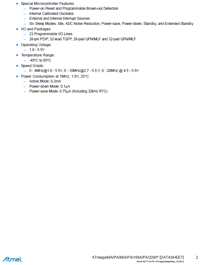
Ausschnitt eines ATmega-Datenblatts mit technischen Merkmalen
Power-down, Standby, and Extended Standby I/O and Packages - 23 Programmable I/O Lines - 28-pin PDIP, 32-lead TQFP, 28-pad QFN/MLF and 32-pad QFN/MLF Operating Voltage: - 1.8 - 5.5V Temperature Range: - -40°C to 85°C Speed Grade: - 0 - 4MHz@1.8 - 5.5V, 0 - 10MHz@2.7 - 5.5V, 0 - 20MHz @ 4.5 - 5.5V Power
in „ATmega: unerwatetes Reset“ · Mikrocontroller und Digitale Elektronik · · Screenshots
-
Datei
Lcd_4x20.bas
Program name: Testboard - Version : 1.0 21.07.2004 ** ' ** Compiler : BASCOM AVR, ( V1.11.7.4) ** ' ** ATMEGA32 LCD-Board 4x20 ** ' ** ** ' ** ** ' ** Referenz Prozessor = 12.0000 MHz ** ' ** ** ' ** ** ' ** ** ' ** Written by: Sepp Bartl ** ' ********************************************************************** $regfile = "M32def.DAT" 'use the ATMEGA32 file $crystal = 12000000 '$sim 'Osccal = 201 '------------------------------------------------------------------------------- ' Startup Definitions '------------------------
in „BASCOM: große Zahlen über alle 4 Zeilen eines 4-Zeiligen L“ · Projekte & Code ·
-
Datei
Phase90Degree.asm
Phase90Degree.asm ; --------------------------------------------------------- ; Programm Purpose: ; ; Use ATmega32 with 8 MHz Quarz ; ; It shall generate at the Ports OC1A (Port D4) und OC1B (Port D5) ; the following waveform: ; ; OC1A --____----____---- ; OC1B ----____----____-- ; ; with a frequency of 40 KHz
in „Timer/Counter1 ATmega32“ · Mikrocontroller und Digitale Elektronik ·
-
Datei
Lauftext.asm
/* * Lauftext.asm * * Created: 02.03.2018 19:20:32 * Author: P?ch */ ;---------------------------------------------------------------------- ; Titel :Lauftext Atmega ;---------------------------------------------------------------------- ; ;---------
in „LCD Lauftext Atmega8“ · Mikrocontroller und Digitale Elektronik ·
-
Datei
uart.h
circular receive buffer, must be power of 2 */ #ifndef UART_RX_BUFFER_SIZE #define UART_RX_BUFFER_SIZE 32 #endif /** Size of the circular transmit buffer, must be power of 2 */ #ifndef UART_TX_BUFFER_SIZE #define UART_TX_BUFFER_SIZE 32 #endif /* test if the size of the circular buffers fits into SRAM */
in „AVR Bootloader in C, geht mit mega8 nicht“ · Mikrocontroller und Digitale Elektronik ·
-
Datei
uart.c
#define UART0_CONTROL UCSRB #define UART0_DATA UDR #define UART0_UDRIE UDRIE #elif defined(__AVR_ATmega8__) || defined(__AVR_ATmega16__) || defined(__AVR_ATmega32__) \ || defined(__AVR_ATmega8515__) || defined(__AVR_ATmega8535__) \ || defined(__AVR_ATmega323__) /* ATMega with one USART */ #define ATMEGA_USART
in „UART im AVR Studio simulieren“ · Mikrocontroller und Digitale Elektronik ·
-
Datei
SpiDefs.h
containing plattform specific and low level definitions for * the SPI functionality */ #if defined(__AVR_ATmega16__) || defined(__AVR_ATmega32__) #define SPI_PORT PORTB #define SPI_DDR DDRB #define SPI_SS 4 #define SPI_MOSI 5 #define SPI_MISO 6 #define SPI_SCLK 7 #elif defined(__AVR_ATmega8__) #define SPI_PORT
in „MMC SD library FAT16 FAT32 read write“ · Projekte & Code ·
-
Datei
Arduino_Drehgeber.ino
3 // an PORTD.3 #define MASKE (BIT(PHASE_A)+BIT(PHASE_B)) // vereinfachte Schreibweise volatile int32_t count; // Zaehler per Interrupt int32_t zaehler, alter_zaehler; // Vergleichszaehler fuer neue Ausgabewerte // nur Interrupt PCINT18 (PCINT2-Gruppe) wird zur Auswertung verwendet ISR(PCINT2_vect) {
in „Drehgeber per Interrupt auswerten, AVR“ · Projekte & Code ·
-
Datei
TMC222_AVR.h
library for using a TMC222 together with AVR processors that have a hardware TWI interface (e.g. ATmega8, ATmega48, ATmega88, ATmega168, ATmega16, ATmega32, ATmega64, ATmega128, AT90CAN128 and many more). It implements and interrupt driven TWI master communication over the TWI of the AVR MCU and utilizes
in „Ansteuerung TMC222“ · Mikrocontroller und Digitale Elektronik ·
-
PDF
i2c.pdf
0x50 #define POINTER_ADDRESS 0x00 #define SCL_CLOCK 10000UL uint8_t error1 = 0; #if defined (__AVR_ATmega32__) || (__AVR_ATmega328__) || defined (__AVR_ATmega328P__) || \ defined(__AVR_ATmega168P__) || defined(__AVR_ATmega168PA__) || \ defined(__AVR_ATmega88P__) || \ defined(__AVR_ATmega48P__) || \ defined(__AVR_ATmega1284P__) || \ defined (__AVR_ATmega324A__) || defined (__AVR_ATmega324P__) || defined (__AVR_ATmega324PA__) || \ defined (__AVR_ATmega644__) || defined (__AVR_ATmega644A__) || defined (__AVR_ATmega644P
in „Programm läuft nur mit JTAG Fuse“ · Mikrocontroller und Digitale Elektronik ·
-
Datei
uart.h
int baudrate); /** @brief Get received byte of USART1 from ringbuffer. (only available on selected ATmega) @see uart_getc */ extern unsigned int uart1_getc(void); /** @brief Put byte to ringbuffer for transmitting via USART1 (only available on selected ATmega) @see uart_putc */ extern void uart1_putc(unsigned
in „Timerberechnung die hunderste“ · Mikrocontroller und Digitale Elektronik ·
-
Datei
uart.h
int baudrate); /** @brief Get received byte of USART1 from ringbuffer. (only available on selected ATmega) @see uart_getc */ extern unsigned int uart1_getc(void); /** @brief Put byte to ringbuffer for transmitting via USART1 (only available on selected ATmega) @see uart_putc */ extern void uart1_putc(unsigned
in „Wie macht man solche Lichtmodes? Lauflicht, PWM und Co“ · Mikrocontroller und Digitale Elektronik ·