-
Datei
meindef.h
bit40:1; u8 bit41:1; u8 bit42:1; u8 bit43:1; u8 bit44:1; u8 bit45:1; u8 bit46:1; u8 bit47:1; u8 bit48:1; u8 bit49:1; u8 bit50:1; u8 bit51:1; u8 bit52:1; u8 bit53:1; u8 bit54:1; u8 bit55:1; u8 bit56:1; u8 bit57:1; u8 bit58:1; u8 bit59:1; u8 bit60:1; u8 bit61:1; u8 bit62:1; u8 bit63:1; } bitfeld64; typedef
in „I2C Display einfache Frage“ · Mikrocontroller und Digitale Elektronik ·
-
Datei
meindef.h
bit40:1; u8 bit41:1; u8 bit42:1; u8 bit43:1; u8 bit44:1; u8 bit45:1; u8 bit46:1; u8 bit47:1; u8 bit48:1; u8 bit49:1; u8 bit50:1; u8 bit51:1; u8 bit52:1; u8 bit53:1; u8 bit54:1; u8 bit55:1; u8 bit56:1; u8 bit57:1; u8 bit58:1; u8 bit59:1; u8 bit60:1; u8 bit61:1; u8 bit62:1; u8 bit63:1; } bitfeld64; typedef
in „AVR-Studio 4.19 und JTAG ICE MK2 unter Windows 11 64 Bit installieren“ · Mikrocontroller und Digitale Elektronik ·
-
Datei
irmp.c
Supported AVR mikrocontrollers: * * ATtiny87, ATtiny167 * ATtiny45, ATtiny85 * ATtiny44, ATtiny84 * ATmega8, ATmega16, ATmega32 * ATmega162 * ATmega164, ATmega324, ATmega644, ATmega644P, ATmega1284, ATmega1284P * ATmega88, ATmega88P, ATmega168, ATmega168P, ATmega328P * * This program is free software; you
in „IRMP - Infrared Multi Protocol Decoder“ · Projekte & Code ·
-
 Bild
Bild
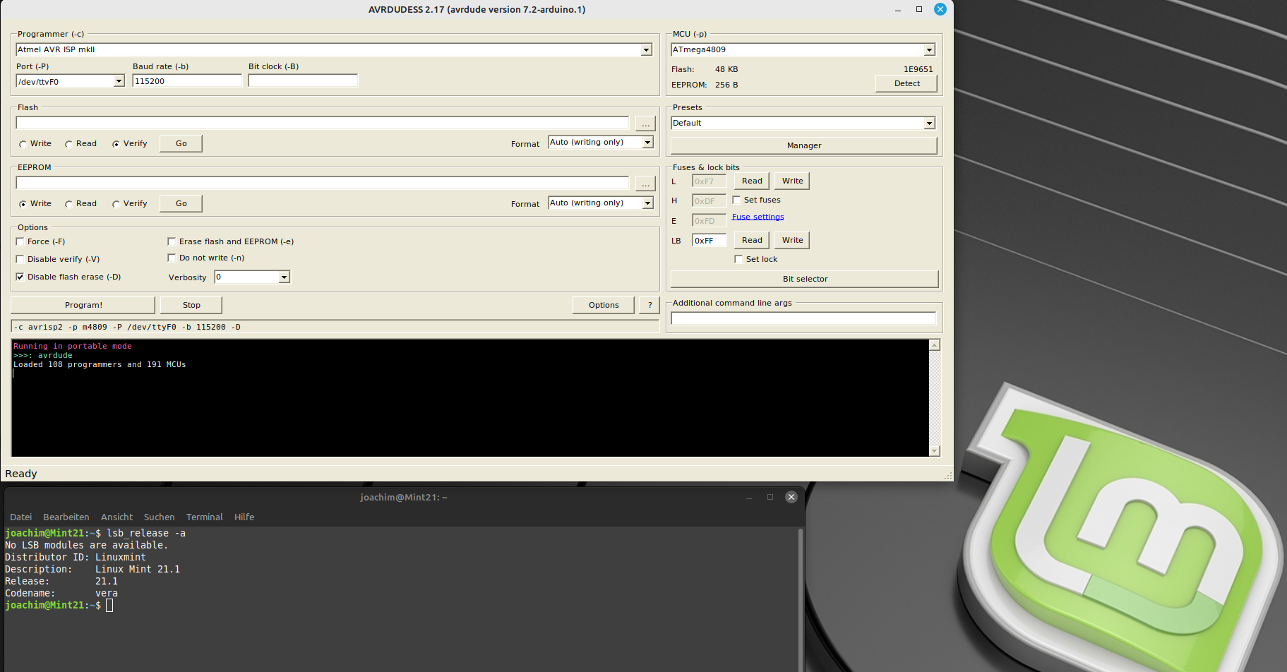
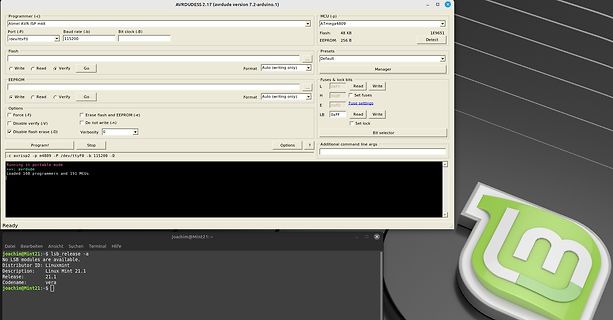
AVRDUDE Software und Linux Terminal
AVRDUDE 2.17 -arduino version 7.2-arduino.1. MCU (-p) ATmega4809 Flash: 48 KB EEPROM: Detect Port (-p) /dev/ttyf0 Baud rate (-b) 115200 Bit clock (-c) Options: Force (-F) Disable verify (-V) Disable flash erase (-D Erase flash and EEPROM (-e) Do not write (-
in „neuer Artikel: Qt Creator als IDE für Mikrocontroller“ · Mikrocontroller und Digitale Elektronik · · Screenshots
-
 Bild
Bild
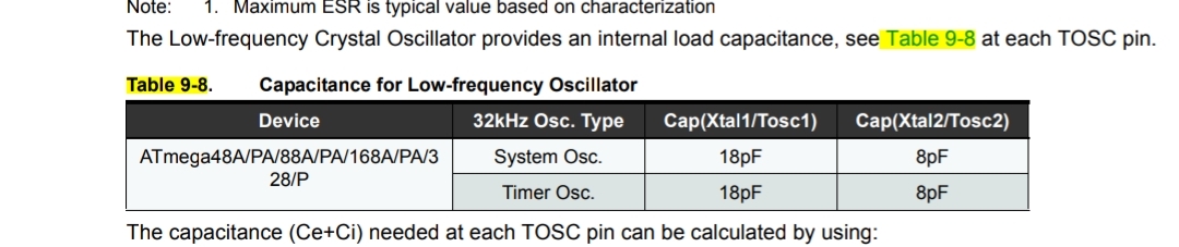
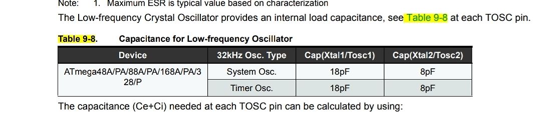
Tabellenausschnitt aus einem Datenblatt für Mikrocontroller
Capacitance for Low-frequency Oscillator Device | 32kHz Osc. Type | Cap(Xtal1/Tosc1) | Cap(Xtal2/Tosc2) ATmega48A/PA/88A/PA/168A/PA/328/P | System Osc. | 18pF | 8pF | Timer Osc. | 18pF | 8pF The capacitance (Ce+Ci) needed at each TOSC pin can be calculated by using:
in „Schaltung Messung kleiner Ströme bei uC in Standby/Idle“ · Analoge Elektronik und Schaltungstechnik · · Screenshots
-
Datei
main.c
an Port D //---------------------------------------------------------------------- // Prozessor : ATmega8/48/88/168 // Takt : 3.6864 MHz // Sprache : C // Datum : // Version : // Autor : // Name des Programmes in der Makefile : main.c // //--------------------------------------------------------------
in „Anfänger Problem mit dem Makefile“ · Mikrocontroller und Digitale Elektronik ·
-
 Bild
Bild
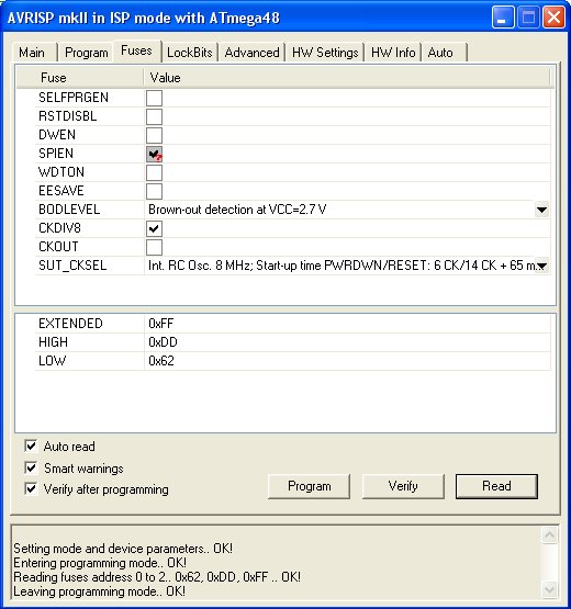
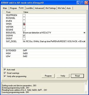
AVRISP mkII Software zur AVR-Programmierung
AVRISP mkII in ISP mode with ATmega48 Main Program Fuses LockBits Advanced HW Settings HW Info Auto Fuse Value SELFPRGEN RSTDISBL DWEN SPIEN WDTON EESAVE BODLEVEL Brown-out detection at VCC=2.7 V CKDIV8 CKOUT SUT_CKSEL Int. RC Osc. 8
in „ATMega48 - hohe Stromaufnahme im Idle Mode?“ · Mikrocontroller und Digitale Elektronik · · Screenshots
-
PDF
ATmega32.pdf
and TCNT1. The OC1x Interrupt Flag will be set when a compare match occurs. 103 2503Q–AVR–02/11 ATmega32(L) Figure 48. Phase and Frequency Correct PWM Mode, Timing Diagram OCnA Interrupt Flag Set or ICFn Interrupt Flag Set (Interrupt on TOP) OCRnx / TOP Update and TOVn Interrupt Flag Set (Interrupt
in „STK500 als ISP“ · Mikrocontroller und Digitale Elektronik ·
-
Datei
GSM_GPS_Shield.cpp
= 0; int sim_error = 0; int reg_OK = 0; char temp_in[10]; SPI spi=SPI(); // Arduino Duemilanove (ATmega328) & Arduino UNO (ATmega 328) GSM::GSM(int powerON_pin, int baud) { pinMode(powerON_pin, OUTPUT); // Pin 7 _powerON_pin = powerON_pin; _baud = baud; } void GSM::initializeGSM(char pwd[20]) { Serial.begin
in „Arduino + GSM-GPRS-GPS-Shield“ · Mikrocontroller und Digitale Elektronik ·
-
Datei
doubledigitavrfibo.s
; Fibonacci sequence generator for ATmega328p ; Outputs 80-digit numbers via UART ; Optimized to store 2 digits per byte .include "m328pdef.inc" .equ F_CPU = 16000000 ; CPU Frequency .equ BAUD = 9600 ; Desired Baud Rate .equ UBRR_VAL = (F_CPU
in „Wettkampf Opa(MOS6502) gegen Frischling(ATmega)“ · Mikrocontroller und Digitale Elektronik ·
-
Datei
irmpconfig.h
IRMP_SUPPORT_LGAIR_PROTOCOL 1 // LG Air Condition >= 10000 ~300 bytes #define IRMP_SUPPORT_SAMSUNG48_PROTOCOL 1 // Samsung48 >= 10000 ~100 bytes (SAMSUNG must be enabled!) #define IRMP_SUPPORT_MERLIN_PROTOCOL 1 // Merlin >= 15000 (better 20000) ~300 bytes #define IRMP_SUPPORT_PENTAX_PROTOCOL 1 // Pentax
in „Umfrage: welche IR-Protokolle nutzt ihr mit IRMP?“ · PC Hard- und Software ·
-
Datei
main.c
include <avr/interrupt.h> #include <stdint.h> //#include <util/delay.h> //--------------------------ATMEGA48------------intern 8Mhz--- volatile unsigned short i; ISR(TIMER1_COMPA_vect){ OCR1A=i; //aktualisierung des Vergleichregisters } int main(){ TCCR1A |= (1<<COM1A0); //Umschalten des Ausgangs OC1A TCCR1B
in „Timer1 Compare Mode Probleme,Mega16“ · Mikrocontroller und Digitale Elektronik ·
-
Datei
boot.c
volatile("nop"); } while(1); } /* --------- do.bat --------- echo compile... avr-gcc -g -Os -mmcu=atmega16 -c boot.c echo link... avr-gcc -g -mmcu=atmega16 -Wl,-Map,boot.map,--cref,--section-start=.bootloader=0x1c00 -o boot.elf boot.o echo creating lst file... avr-objdump -h -S -d boot.elf > boot.lst
in „bootloader section in c“ · Mikrocontroller und Digitale Elektronik ·
-
Datei
main.c
NOKIA 3310 Display ***** //******************************************************** //Controller: ATmega32 (Clock: 1 Mhz-internal) //Compiler: ImageCraft ICCAVR //Author: CC Dharmani, Chennai (India) //Date: Sep 2008 //******************************************************** #include <avr/io.h> #include
in „Nokia 3310 Display an Atmega32 will nicht“ · Mikrocontroller und Digitale Elektronik ·
-
Datei
millisek_demo.c
----------- millisek_demo.c --------------------------- Demo fuer Zeitmessung Millisekunde MCU : ATmega48 .. ATmega328 10.08.2016 R. Seelig -------------------------------------------------------------------- */ #include <avr/io.h> #include <avr/pgmspace.h> #include <avr/interrupt.h> #include <stdarg.h
in „Arduino Zeitmessung mit externes Modul das ms messen kann?“ · Mikrocontroller und Digitale Elektronik ·
-
PDF
Amadeus.pdf
Tested - High-voltage serial programming ATtiny12 Tested - High-voltage serial programming only ATmega48 Not Tested* ATmega8 Not Tested* ATmega88 Not Tested* ATmega8515 Not Tested ATmega8535 Not Tested ATmega16 Not Tested ATmega162 Not Tested ATmega168 Not Tested* ATmega169 Not Tested ATmega32 Not Tested ATmega325 Not Tested* ATmega3250 Not Tested* ATmega329 Not Tested* ATmega3290 Not Tested* ATmega64 Tested ATmega645 Not Tested* ATmega6450 Not Tested* ATmega649 Not Tested* ATmega6490 Not Tested* ATmega128
in „USB-Programmer PIC/AVR Jetzt auch auf Deutsch :-)“ · Mikrocontroller und Digitale Elektronik ·
-
 Bild
Bild
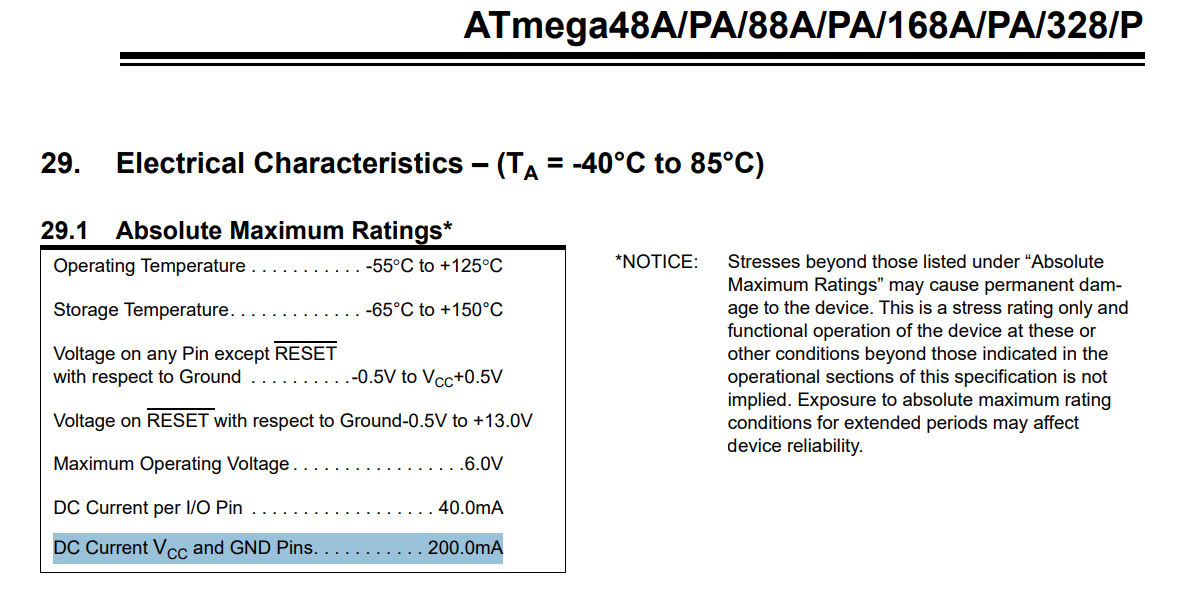
Ausschnitt aus einem Datenblatt der ATmega-Serie
ATmega48A/PA/88A/PA/168A/PA/328/P 29. Electrical Characteristics – (TA = -40°C to 85°C) 29.1 Absolute Maximum Ratings* Operating Temperature . . . -55°C to +125°C Storage Temperature . . . -65°C to +150°C
in „7-Segment LEDs ansteuern“ · Mikrocontroller und Digitale Elektronik · · Screenshots

-
PDF
readme_131206.pdf
Lib in Python3.2 (für XBee ZB Module im API-Modus) Bislang sind meine Router und der Coordinator anATMega's angeschlossen und die Software ist in C geschrieben. Zumindest der Coordinator soll in Zukunft direkt an der serielle Schnittstelle eines PC's oder RaspberryPi's seinen Dienst tun, damit dort Daten
-
PDF
ATmega8_L__Summary.pdf
ATmega8L-8AI 32A 8 2.7 - 5.5 (2) 32A ATmega8L-8AU ATmega8L-8PI 28P3 Industrial ATmega8L-8PU (2) 28P3 (-40C to 85C) ATmega8L-8MI 32M1-A ATmega8L-8MU (2) 32M1-A ATmega8-16AC 32A Commercial ATmega8-16PC 28P3 (0°C to 7C) ATmega8-16MC 32M1-A ATmega8-16AI 32A 16 4.5 - 5.5 (2) 32A ATmega8-16AU ATmega8-16PI 28P3 Industrial ATmega8-16PU (2) 28P3 (-40C to 85C) ATmega8-16MI (2) 32M1-A ATmega8-16MU 32M1-A Notes: 1. This device can
in „Daten im EEProm aufzeichnen und später über RS232 senden“ · Mikrocontroller und Digitale Elektronik ·
-
Datei
dcf77decode.asm
hilf breq S43 dec hilf breq S44 dec hilf breq S45 dec hilf breq S46 dec hilf breq S47 dec hilf breq S48 dec hilf breq S49 dec hilf breq S50 ;Zwischensprünge 41-50 S41: rjmp SECOND41 S42: rjmp SECOND42 S43: rjmp SECOND43 S44: rjmp SECOND44 S45: rjmp SECOND45 S46: rjmp SECOND46 S47: rjmp SECOND47 S48: rjmp SECOND48 S49: rjmp SECOND49 S50: rjmp SECOND50 ;Zielsuche 51-60 dec hilf breq S51 dec hilf breq S52 dec hilf breq S53 dec hilf breq S54 dec hilf breq S55 dec hilf breq S56 dec hilf breq S57 dec hilf breq S58
in „Probleme mit DCF77-Decodierprogramm“ · Mikrocontroller und Digitale Elektronik ·
-
Datei
incap.c
/* Input capture Beispiel, für einen Atmega48 Autor: J.Gerlach Idee: aus dem mikrocontroller.net forum */ #include <avr/io.h> #include <avr/interrupt.h> #include <inttypes.h> // globals volatile uint16_t dif; int main(void) { DDRD =0x00; /*
in „Input Capture Flag Atmega16“ · Mikrocontroller und Digitale Elektronik ·
-
PDF
CFAG12864BTFHV_v3.0.pdf
www.neotec.com.tw Appendix Neotec Semiconductor Ltd. 新 德 科 技 股 份 有 限 公 司 NT7107 LCD Driver TIMING DIAGRAM 1/48 DUTY TIMING (MASTER MODE) Condition: DS1=L, DS2=L, SHL=H (L), PCLK2=H C CLK1 1 2 3 63 64 CLK2 1 2 3 46 47 48 1 2 3 46 47 48 CL2 FRM DIO1 (DIO2) M V0 V0 C1 (C48)V1 V4 V1 V5 V0 C2 (C47)V1 V4 V4 V1 V1 V4
in „avr asm LCD Problem“ · Mikrocontroller und Digitale Elektronik ·
-
Datei
debug_okay.asm
rjmp .-20 ; 0x472 <spi_transmit+0x4> } } 486: 08 95 ret 00000488 <__vector_2>: #if defined(__AVR_ATmega8__) || defined(__AVR_ATmega88A__) || defined(__AVR_ATmega168__) ISR( INT1_vect ) #else # error MCU MODEL NOT SUPPORTED #endif // defined(__AVR_ATmega8__) || defined(__AVR_ATmega88A__) || defined(__AVR_ATmega168__) { 488: 1f 92 push r1 48a: 0f 92 push r0 48c: 0f b6 in r0, 0x3f ; 63 48e: 0f 92 push r0 490: 11 24 eor r1, r1 492: 8f 93 push r24 // just flag the IRQ (processing of status/data as well as resetting
in „Fehler bei einfacher Integer-Division?“ · Mikrocontroller und Digitale Elektronik ·
-
Datei
first_contact.asm
/* Programm : FirstContact MCU : ATMega48 Funktion : Erster Test: Schalter einlesen, LED ausgeben. HW : MyAVR Board : Port D 2/3: Schalter Port C 0/1: LED */ .include <m88pdef.inc> /* Interrupt-Vektoren */ rjmp main reti reti reti reti reti
in „AVR Einsteigerproblem“ · Mikrocontroller und Digitale Elektronik ·
-
Datei
lcd_test.c
: Peter Fleury <pfleury@gmx.ch> http://jump.to/fleury File: $Id: test_lcd.c,v 1.3 2003/12/10 19:32:48 peter Exp $ Software: AVR-GCC 3.3 Hardware: HD44780 compatible LCD text display ATS90S8515/ATmega if memory-mapped LCD interface is used any AVR with 7 free I/O pins if 4-bit IO port mode is used ***
in „HD44780 atmega168“ · Mikrocontroller und Digitale Elektronik ·
-
PDF
AD9952arduino.pdf
******* 2 ;* Test: Ansteuerung eines DDS-Chips AD9952 von Analog Devices * 3 ;* Arduino 2009 mit ATmega328P, 16 MHz Quarz * 4 ;* Portbelegungen: LCD:PC0-3=DB4-7,PC4=RS,PC5=R/W PD7=E_LCD * 5 ;* DDS: PB0=RESET, PB1=/CS, PB2=I/O-UPDATE, PB3=SDIO, PB4=SDO, PB5=SCLK * 6 ;* PD0/1 frei für UART, PD2/3=Drehgeber
in „DDS-Chip mit einem AVR ansprechen“ · Mikrocontroller und Digitale Elektronik ·
-
PDF
ds18b20_pre1.pdf
be done by us. To continue, you just need the materials listed below: ● 1-AVR Microcontroller (ex.Atmega8) ● 1- DS18B20Digital temperaturesensor ● 1- 4K7 Resistor ● AworkingAVRToolchain If you find anymistake in this document,please, reportit at gerardmarull@gmail.com. Notes: In the preliminary version
in „Atmega 8 + dallas 18s20 + Neuling (never ending story)“ · Mikrocontroller und Digitale Elektronik ·
-
Datei
Inputs.ino
PIN_RESERVED 3 Encoder encoders[4]; // input pins autofilled based on which mpu #if defined(__AVR_ATmega1280__) || defined(__AVR_ATmega2560__) int inputPins[] = {A0, A1, A2, A3, A4, A5, A6, A7, A8, A9, A10, A11, A12, A13, A14, A15, 2, 3, 4, 5, 6, 7, 8, 9, 10, 11, 12, 13, 14, 15, 16, 17, 18, 19, 22, 23, 24, 25, 26, 27, 28, 29, 30, 31, 32, 33, 34, 35, 36, 37, 38, 39, 40, 41, 42, 43, 44, 45, 46, 47, 48, 49, 50, 51, 52, 53}; Input inputs[66]; int memoryLocationEncoder = 2300; int memoryLocationMatrix = 2000; int memoryLocationDeviceID = 4000; #elif defined(__AVR_ATmega328P__) int inputPins[] = {A0,
in „Dauerkontakt vom Schalter in Impuls umwandeln“ · Analoge Elektronik und Schaltungstechnik ·
-
Datei
main.cpp
/* * main.cpp * * Created on: 22.11.2014 * Author: thomas * µC Atmega48 @ 20Mhz */ #include "main.hpp" GPIO GPIOInj1(PortB, 1), GPIOInj2(PortB, 2), GPIOInj3(PortC, 3), GPIOInj4(PortD, 4), GPIODuoLed(PortC, 8), GPIOInput1(GPIOInput, PortD, 1), GPIOInput2(GPIOInput, PortD
in „C++ auf einem MC, wie geht das?“ · Mikrocontroller und Digitale Elektronik ·
-
PDF
xbee_DS18B20.pdf
senden anhängen +3V gnd 4.7k DS18B20 Temperatursensoren DS18B20 DS18B20 RTS SLEEP DQ 15 16 15 13 XBee ATMega48 2 3 6 2 3 4 INT0 Stromversorgung, 10k 470 470 470 1k 100k Quarz 3.686.400 MHz und Kondensatoren sind nicht dargestellt ! BC 337 o.ä. associateRSSI Sleep PWM gnd gnd gnd gnd
in „XBee for NewBees (DOS-Tool zum Testen von XBee's im API-Modus)“ · Projekte & Code ·
-
Datei
3310LCD.c
NOKIA 3310 Display ***** //******************************************************** //Controller: ATmega32 (Clock: 1 Mhz-internal) //Compiler: ImageCraft ICCAVR //Author: CC Dharmani, Chennai (India) //Date: Sep 2008 //******************************************************** #include <avr/io.h> #include
in „Ladegerät für NiMH Akku mit 3310 display“ · Mikrocontroller und Digitale Elektronik ·
-
Datei
SINUS_COSINUS.asm
; Bernhard.Erfurt@gmx.de ; SINUS und KOSINUS - FUNKTION ; 05/2006 ; ATmega8 .include "m8def.inc" ; REGISTER .def temp = R16 .def temp1 = R17 .def temp2 = R18 .def temp3 = R19 .def temp4 = R20 .def temp5 = R21 .def temp6 = R22 .def temp7 = R23 .def temp8 = R24 .def temp9 = R25 .cseg ;Beginn eines Code-Segmentes .org 0 ;Startadresse=0 ; INTERRUPT-VECTOREN für ATmega8 rjmp RESET ; Reset Handler reti ;rjmp EXT_INT0 ; IRQ0 Handler reti ;rjmp EXT_INT1 ; IRQ1 Handler reti ;rjmp TIM2_COMP ; Timer2 Compare Handler reti ;rjmp TIM2_OVF ; Timer2 Overflow Handler reti ;rjmp
in „SINUS - COSINUS / KOSINUS - BEISPIEL (Assembler) ATmega8“ · Projekte & Code ·
-
PDF
AVRMKII_EN3.pdf
NTRODUCTION 1.1 What is AVR MKII? AVR MKII is a USB in-circuit programmer for controllers: Attiny, Atmega and Xmega. It cooperate with Atmel Studio and AvrDude. This AVR programmer is LUFA powered which is open source software that emulates AVRISP-MKII functionality, programmer is supported by ATMEL STUDIO
in „OLIMEX ATEMGA8 - Debugging-Modus funktioniert nicht“ · Mikrocontroller und Digitale Elektronik ·
-
Datei
Main_c.txt
// Define BAUD rate and F_CPU in #UART.h /* * Main.c * * Created: 06.12.2021 14:57:48 */ //controller: ATMEGA328P (same mikrocontroller as on Arduino UNO) #include <stdio.h> #include <avr/io.h> #include "UART.h" #include <util/delay.h> #include <avr/interrupt.h> #include <string.h> #include
in „Atmega328p + AS7261 I2C kein Ack vom slave“ · Mikrocontroller und Digitale Elektronik ·
-
PDF
schematic.pdf
ATMega48P LCD 2x8 (Pollin) R1/1M R2/1M (+) 19 13 10 PB5 PD7 D7 12 9 LiPo−Akku R3/330K 18 PD6 D6 (−) 3.7V/800mA PB4 11 8 R4/47K PD5 D5 17 6 7 PB3 PD4 D4 4 6 (+) R5/6K8 16 PD2 EN TP4056 PB2 C4 5 Lade−Modul
in „Selbsthaltung vom Schaltregler mit Mikrocontroller und einem Taster für An/Aus ?“ · Mikrocontroller und Digitale Elektronik ·
-
PDF
schematic.pdf
ATMega48P LCD 2x8 (Pollin) R1/1M R2/1M (+) 19 13 10 PB5 PD7 D7 12 9 LiPo−Akku R3/330K 18 PD6 D6 (−) 3.7V/800mA PB4 11 8 R4/47K PD5 D5 17 6 7 PB3 PD4 D4 4 6 (+) R5/6K8 16 PD2 EN TP4056 PB2 C4 5 Lade−Modul
in „Widerstandsmessung“ · Analoge Elektronik und Schaltungstechnik ·
-
PDF
schematic.pdf
ATMega48P LCD 2x8 (Pollin) R1/1M R2/1M (+) 19 13 10 PB5 PD7 D7 12 9 LiPo−Akku R3/330K 18 PD6 D6 (−) 3.7V/800mA PB4 11 8 R4/47K PD5 D5 17 6 7 PB3 PD4 D4 4 6 (+) R5/6K8 16 PD2 EN TP4056 PB2 C4 5 Lade−Modul
-
Datei
mendelmultimaterial.txt
/tools/avr/bin/avr-g++ -c -g -Os -Wall -fno-exceptions -ffunction-sections -fdata-sections -mmcu=atmega1284p -DF_CPU=16000000L -MMD -DUSB_VID=null -DUSB_PID=null -DARDUINO=104 -I/home/gerd/Programme/arduino-1.0.4/hardware/arduino/cores/arduino -I/home/gerd/Programme/arduino-1.0.4/hardware/arduino/variants
in „Seltsame Probleme bei Elektronik mit ATmega1284p nach Firmware-Update“ · Mikrocontroller und Digitale Elektronik ·
-
Datei
ExternalTick.ino
AtomicSection ATOMIC_BLOCK(ATOMIC_RESTORESTATE) // http://ww1.microchip.com/downloads/en/DeviceDoc/ATmega48A-PA-88A-PA-168A-PA-328-P-DS-DS40002061A.pdf volatile uint16_t overflowCount; uint32_t getTicks() { union // AVR only hack { uint32_t ticks; struct { uint16_t lower; uint16_t upper; }; } t; AtomicSection
in „Arduino Interrupt Drehzahlmessung Faulhaber Motor“ · Mikrocontroller und Digitale Elektronik ·
-
Datei
main.c
'Blinken' auf GPIO-A */ #define F_CPU 16000000UL #include "util/delay.h" #include "avr/io.h" // ATmega48PA ATtiny841 #define SPI_DDR DDRB // DDRA #define SPI_PORT PORTB // PORTA #define SCK PB5 // PA4 #define MISO PB4 // PA5 #define MOSI PB3 // PA6 #define SS PB2 // A7 #define MCP_OPC 0x40 #define IODIRA
in „SPI mit Attiny 841 und MCP23S17“ · Mikrocontroller und Digitale Elektronik ·
-
Datei
TCB_A2_perCCL_II.asm
Mode' liefert kein Ausgangssignal: erzeugen per CCL AVR® DB Family: AVR128DA28, AVR128DB28, AVR128DB48 megaAVR® 0-series: ATmega4809 ... ... ... ;****************************************************** ; Beispiel: Systemtakt/16000 auf A2: sbi VPORTA_DIR,2 putiw TCB0_CCMP,4000 -1 puti TCB0_CTRLB,0b0_0_0
in „Frage zu CCL-Einheit in neueren AVR-Controllern“ · Mikrocontroller und Digitale Elektronik ·
-
 Bild
Bild
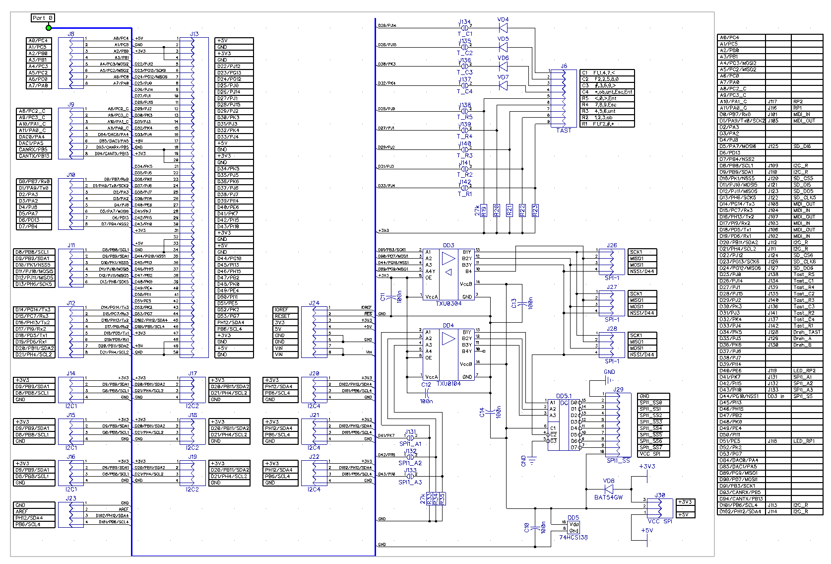
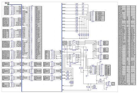
Schaltplan eines Mikrocontroller-Systems mit SPI und I2C
ATmega8, SPI, I2C, J13, J14, J17, J28, J24, J26, J34, J36, J38, J40, J42, J44, J46, J48, J50, J52, J54, J56, J58, J60, J62, J64, J66, J68, J70, J72, J74, J76, J78, J80, J82, J84, J86, J88, J90, J92, J94,
in „I2C Display einfache Frage“ · Mikrocontroller und Digitale Elektronik · · Schaltpläne
-
Datei
platformio.ini
# [env:FYSETC_F6] platform = atmelavr extends = common_avr8 board = fysetc_f6 # # Sanguinololu (ATmega644p) # [env:sanguino644p] platform = atmelavr extends = common_avr8 board = sanguino_atmega644p # # Sanguinololu (ATmega1284p) # [env:sanguino1284p] platform = atmelavr extends = common_avr8 board = sanguino_atmega1284p board_upload.maximum_size = 126976 # # Melzi and clones (ATmega1284p) # [env:melzi] platform = atmelavr extends = env:sanguino1284p upload_speed = 57600 # # Sanguinololu (ATmega1284p stock bootloader
in „Ender3 Z-Achse fährt mit Marlin nur nach oben“ · Mechanik, Gehäuse, Werkzeug ·
-
 Bild
Bild
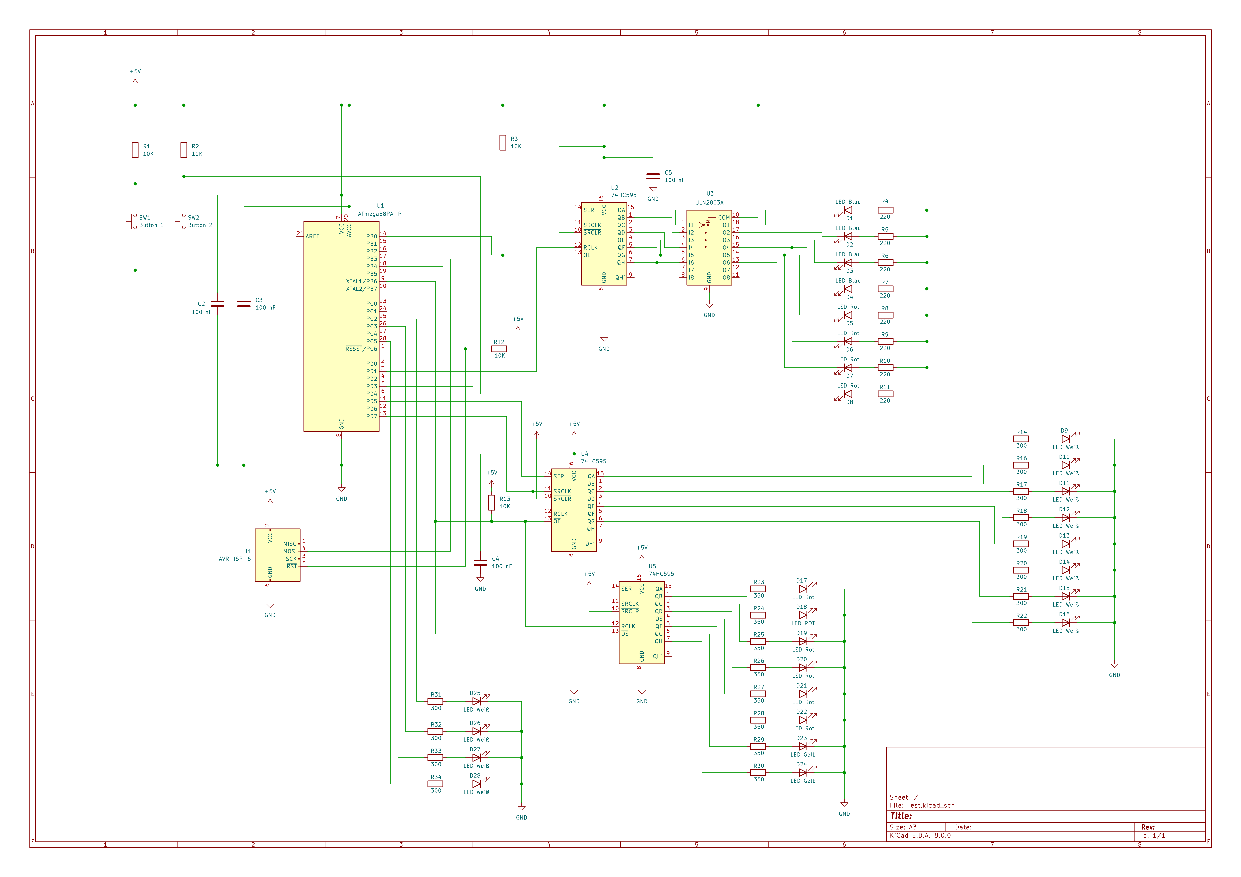
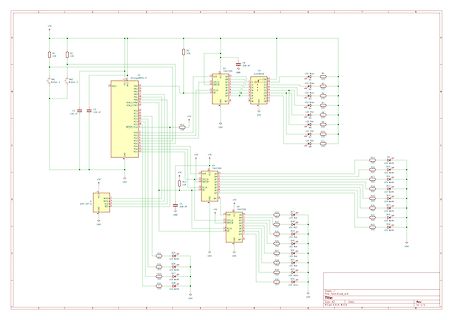
Schaltplan einer Mikrocontroller-Schaltung mit LEDs
SW1 Button 1, SW2 Button 2, R1 10K, U1 ATmega85A-P, R2 470, R3 10K, U2 74HC595, LED Blau R4 220, LED Blau R7 220, LED Rot R8 220, LED Rot R11 220, LED Rot R12 220, LED Rot R16 220, LED Rot R19 220, LED Rot R20 220, LED Rot R21 220, LED Rot R23
in „Fragen zur Schaltung“ · Mikrocontroller und Digitale Elektronik · · Schaltpläne
-
 Bild
Bild
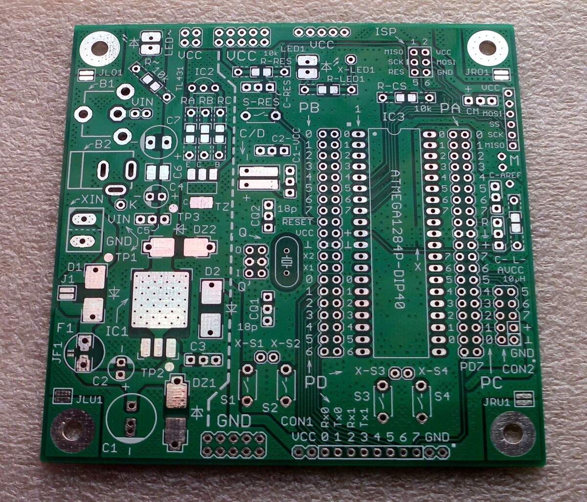
Bestückungsdruck einer grünen Leiterplatte
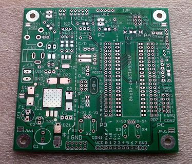
15 16 17 18 19 20 21 22 23 24 25 26 27 28 29 30 31 32 33 34 35 36 37 38 39 40 41 42 43 44 45 46 47 48 49 50 51 52 53 54 55 56 57 58 59 60 61 62 63 64 65 66 67 68 69 70 71 72 73 74 75 76 77 78 79 80 81 82 83 84 85 86 87 88 89 90 91 92 93 94 95 96 97 98 99 100 ATmega1284p-DIP40 AUCC 10uH GND PD7 CON2 PC
in „Entwurf USB-UART-Converter, KiCad, bitte um Review“ · Platinen · · Platinenfotos
-
Datei
srf05_ultraschall.c
// Atmega 48 mit 16Mhz #include <avr/io.h> #include <util/delay.h> #include <stdlib.h> #define SIMULATION 1 #define trigger() DDRD |= (1<<PD0); #define trigger_high() PORTD |= (1<<PD0); #define trigger_low()
in „SRF05 ist mein Quellcode richtig“ · Mikrocontroller und Digitale Elektronik ·
-
Datei
test_7seg.c
Multiplexbetrieb mit drei 7-Segment-Anzeigen, CA, Ansteuerung an PORTB0-B2 mit PNP Transistoren ATMega48 */ #define F_CPU 8000000UL #include <avr/io.h> #include <util/delay.h> uint16_t zahl; uint8_t anzeige[3]; const uint8_t segmenttable[11] = { 0x03, 0xF3, 0x25, 0x0D, 0x99, 0x49, 0x41, 0x1F, 0x01,
in „7-Segment-Ansteuerung“ · Mikrocontroller und Digitale Elektronik ·
-
Datei
Jesper_1x1536x8_9.txt
79,78,77,76,76,75,74,73,73,72,71,71,70,69,69,68 .db 67,66,66,65,64,64,63,62,62,61,60,60,59,58,58,57 .db 56,56,55,54,54,53,53,52,51,51,50,49,49,48,48,47 .db 46,46,45,44,44,43,43,42,42,41,40,40,39,39,38,38 .db 37,36,36,35,35,34,34,33,33,32,32,31,31,30,30,29 .db 29,28,28,27,27,26,26,25,25,24,24,23,23,22,22,22 .db 21,21,20,20,19,19,19,18,18,17,17,17,16,16,15,15
in „DDS normal ?“ · Mikrocontroller und Digitale Elektronik ·
-
Datei
main.c
20, 20, 20, 20, 20, 21, 22, 23, 24, 25, 25, 26, 28, 29, 30, 31, 33, 34, 36, 37, 39, 41, 42, 44, 46, 48, 51, 53, 55, 58, 60, 63, 66, 69, 72, 76, 79, 83, 88, 93, 98,105,113,123,135,154,185,234,185,154,135,123,113,105, 98, 93, 88, 83, 79, 76, 72, 69, 66, 63, 60, 58, 55, 53, 51, 48, 46, 44, 42, 41, 39, 37
in „AVR/GCC: pgm_read_byte funktioniert, pgm_read_word nicht?“ · Mikrocontroller und Digitale Elektronik ·
-
PDF
Atmel-8209-8-bit_AVR_ATmega16M1-32M1-64M1_Datasheet_1_.pdf
Alternate Functions of Port E. Related Links CPU Clock – clkCPU on page 47 I/O Clock – clkI/O on page 48 Flash Clock – clkFLASH on page 48 Asynchronous Timer Clock – clkASY on page 48 ADC Clock – clkADC on page 48 Alternate Functions of Port E on page 110 3.2.7. AV CC AV is the supply voltage pin for the
in „Externer Interrupt“ · Mikrocontroller und Digitale Elektronik ·