-
Datei
main.c
/* * IR_AudioMultiplexer.c * * Created: 30.11.2017 21:39:52 * Author : Kai_Klotz */ //IR Signal_Programm: //#include <inttypes.h> //short forms for various integer types #define F_CPU 1000000UL #include <avr/io.h> #include <avr/interrupt.h> #include
in „IR-Audiomultiplexer Code Error (AVR, C-Code)“ · Mikrocontroller und Digitale Elektronik ·
-
Bild
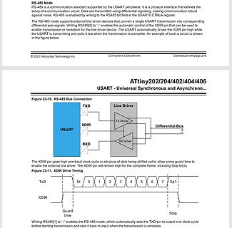
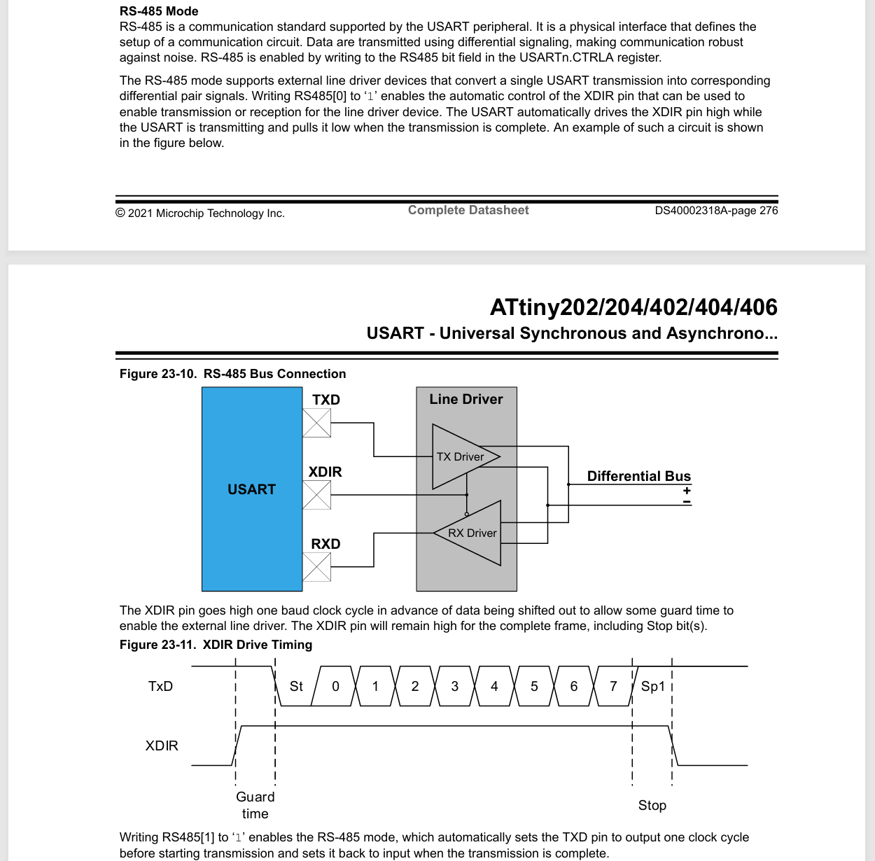
Datenblatt Ausschnitt ATtiny202 RS-485 Modus
RS-485 Mode ATtiny202/204/402/404/406 USART - Universal Synchronous and Asynchrono... Figure 23-10. RS-485 Bus Connection TXD Line Driver XDIR Differential Bus RXD RX Driver Figure 23-11. XDIR Drive Timing TxD St 0 1
in „BME280 mit Attiny85 auslesen Daten per SN75176 an Pi senden“ · Mikrocontroller und Digitale Elektronik · · Screenshots
-
Bild
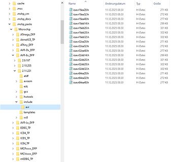
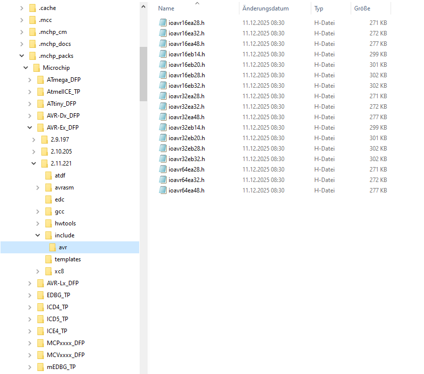
Dateimanager mit AVR-Entwicklungsdateien
.cache .mcc .mchp_cm .mchp_docs .mchp_packs Microchip ATmega_DFP AtmelICE_TP ATtiny_DFP AVR-Dx_DFP AVR-Ex_DFP 2.9.197 2.10.205 2.11.221 atdf avrasm edc gcc hwtools include avr templates xc8 AVR-Lx_DFP EDBG_TP ICD4_TP ICD5_TP ICE4_TP MCPxxxx_DFP MCVxxx_DFP mEDBG_TP
in „Device Packs Unterschiede?“ · Mikrocontroller und Digitale Elektronik · · Screenshots
-
Bild
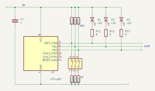
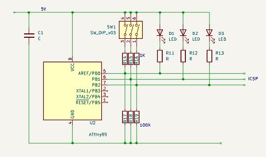
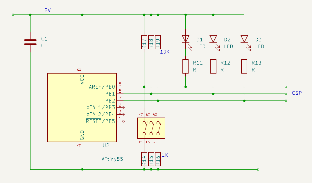
Schaltplan mit ATtiny85 und LEDs
5V C1 C U2 VCC AREF/PB0 PB1 PB2 XTAL1/PB3 XTAL2/PB4 RESET/PB5 GND R17 R18 R19 10K D1 LED R11 R D2 LED R12 R D3 LED R13 R ICSP R14 R15 R16 1K ATtiny85
in „ATtiny keine Pins mehr frei“ · Mikrocontroller und Digitale Elektronik · · Schaltpläne
-
Datei
DUO_LED_12.asm
*********************************************************************** ;* DUO_LED.ASM ;* ;* Für ATtiny26 mit internen Kalibrierten RC-Oszilator von 1Mhz ;* ;* Eine 3-Pinn DUO_LED soll durch die Farben Rot, Gelb und Grün verschiedene ;* ;* Zustände Signalisieren. Diese Grundfarben sollen nochmals durch
-
Bild
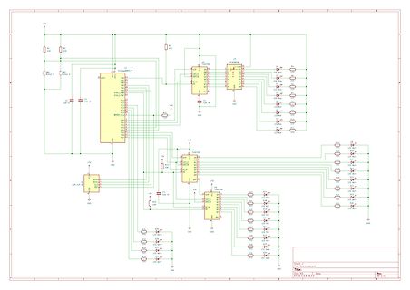
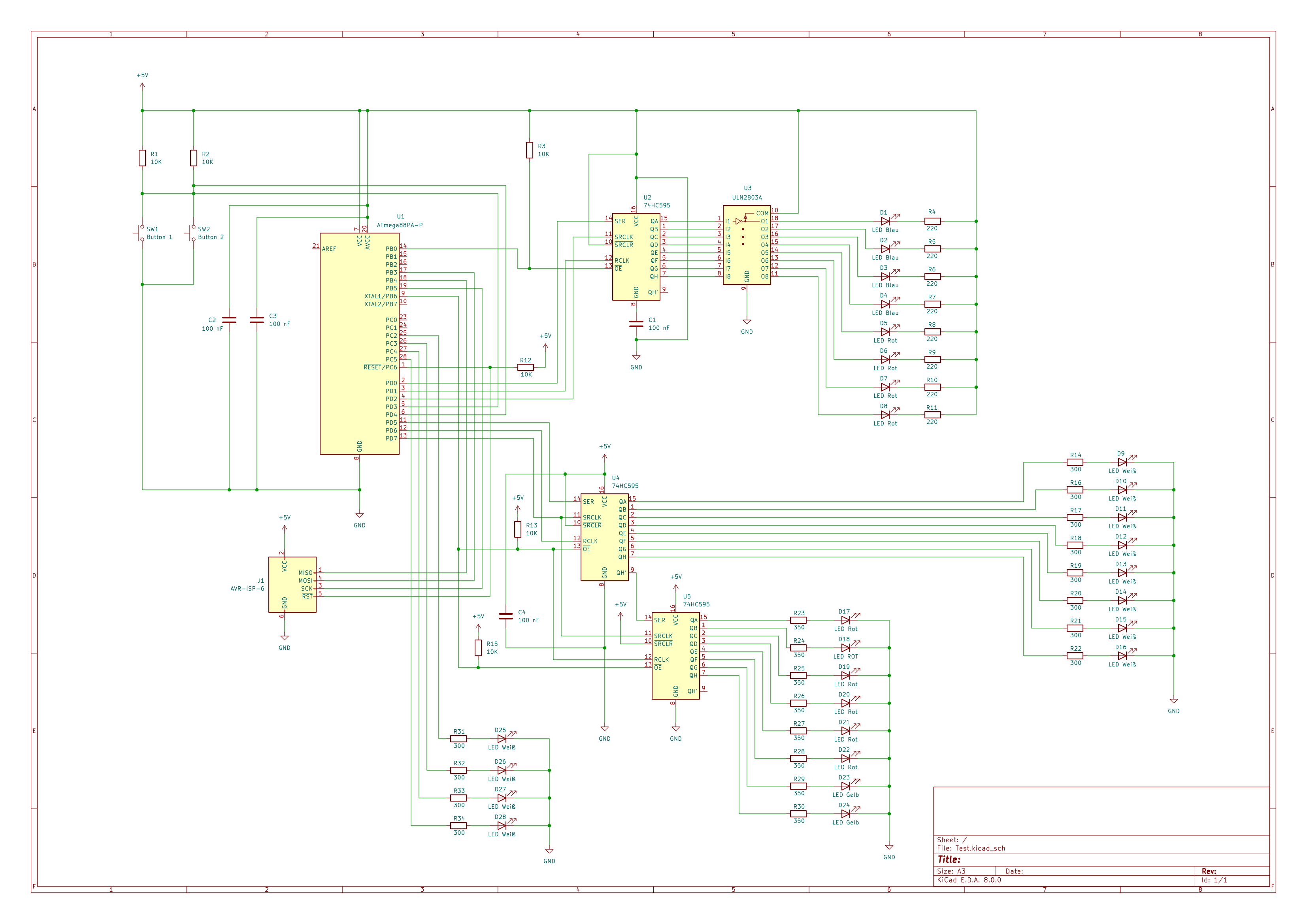
Schaltplan mit ATmega8 und 74HC595
, R2, R3, U1 ATmega8A-PU, C2, C1, U2 74HC595, D1 bis D4, R4 bis R7, U3 74HC595, D5 bis D8, R8 bis R11, U4 74HC595, D9 bis D12, R12 bis R15, U5 ATtiny85, C4, R16 bis R19, GND, +5V
in „Fragen zur Schaltung“ · Mikrocontroller und Digitale Elektronik · · Schaltpläne
-
Bild
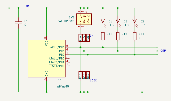
Schaltplan mit ATtiny85 Mikrocontroller
5V, C1, SW1, SW_DIP_x03, 4, 5, 6, 3, 2, 1, D1 LED, D2 LED, D3 LED, R11, R12, R13, R, 1K, R14, R15, R16, VCC, AREF/PB0, PB1, PB2, XTAL1/PB3, XTAL2/PB4, RESET/PB5, U2, ATtiny85, GND, R17, R18, R19, 100K, ICSP
in „ATtiny keine Pins mehr frei“ · Mikrocontroller und Digitale Elektronik · · Schaltpläne
-
Bild
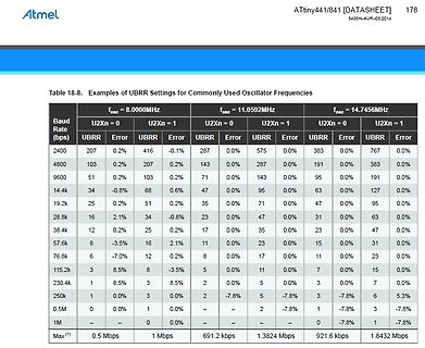
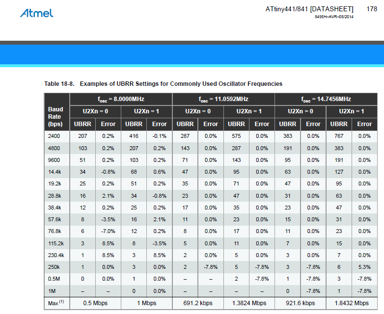
Tabelle mit UBRR-Einstellungen für Oszillatorfrequenzen
Atmel ATtiny441/841 [DATASHEET] 178 Table 18-8. Examples of UBRR Settings for Commonly Used Oscillator Frequencies Baud Rate (bps) fosc = 8.0000MHz fosc = 11.0592MHz fosc = 14.7456MHz U2Xn = 0 U2Xn = 1 U2Xn = 0
in „ATtiny841: Optiboot funktioniert bei 8 MHz nur mit internem Oszillator“ · Mikrocontroller und Digitale Elektronik · · Screenshots
-
Datei
I2Cslave_ATtiny13_Elektor.BAS
SCL=0 sbic pinb,scl rjmp i2c_10 ldi r22,8 'bits to receive=8 lds r23,{address} 'I2C address->R23 I2c_11: sbis pinb,scl 'wait for SCL=1 rjmp i2c_11 sbic pinb,sda rjmp i2c_13 I2c_12: 'if SDA=0 sbic pinb,sda rjmp i2c_wait_for_start ' SDA 0->1? I2CSTOP! (unexpected: wait for next start) sbic pinb,scl rjmp
in „ATTINY13 I2C to Uart converter“ · Mikrocontroller und Digitale Elektronik ·
-
PDF
catalog.pdf
[Category]: Memory [Desc]: NVRAM FRAM Serial-2Wire 512K-Bit 5V 8-Pin SOIC Microcontrollers MPN: ATTINY841-SSU [ID]: 000147 [Price]: 1.38 USD [QTY]: 5 [Category]: Microcontrollers [Desc]: MCU 8-bit ATtiny AVR CISC 8KB Flash 1.8V/2.5V/3.3V/5V 14-Pin Page 50/87 Bauteileliste vom 12.08.2022 SOIC W Tray
-
PDF
catalog.pdf
Bauteileliste vom 12.08.2022 [Desc]: NVRAM FRAM Serial-2Wire 512K-Bit 5V 8-Pin SOIC Microcontrollers MPN: ATTINY841-SSU [ID]: 000147 [Price]: 1.38 USD [QTY]: 5 [Category]: Microcontrollers [Desc]: MCU 8-bit ATtiny AVR CISC 8KB Flash 1.8V/2.5V/3.3V/5V 14-Pin SOIC W Tray MPN: STM32L151CBU6A [ID]: 000148 [Price]
-
Datei
encoder4.c
<avr/sleep.h> #include <avr/eeprom.h> #include <avr/pgmspace.h> #include <util/delay.h> // CPU: ATTiny44-20PU 8MHz // ======================================================================= // Ein-/Ausgänge // ----------------------------------------------------------------------- #define ENCODER_PORT
in „attiny13 aufwecken aus power down modus“ · Mikrocontroller und Digitale Elektronik ·
-
Bild
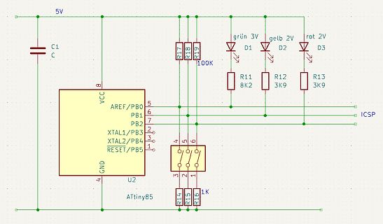
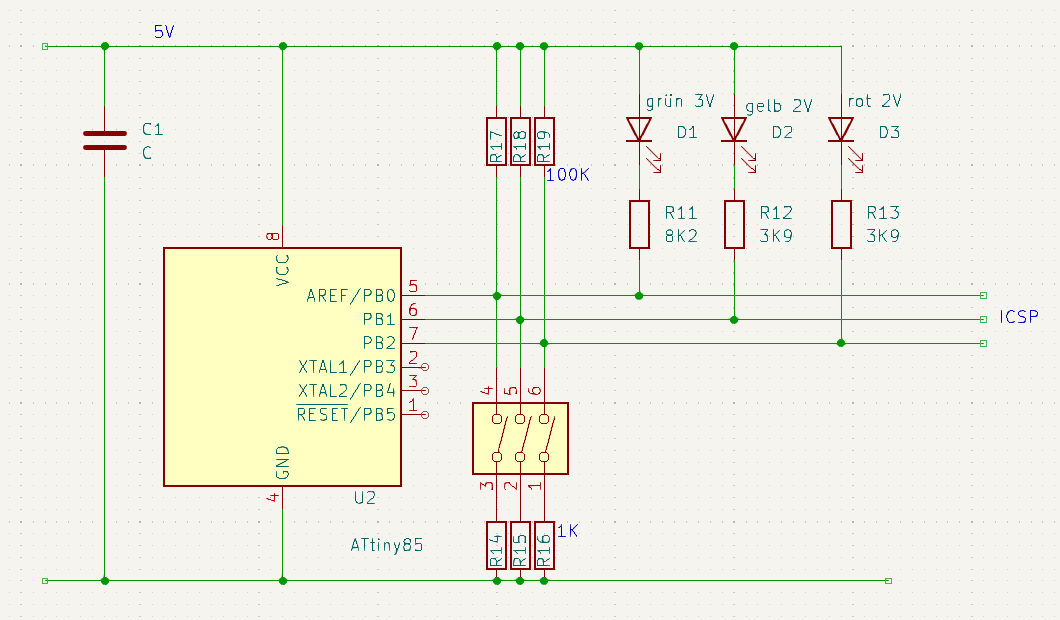
Schaltplan mit ATtiny85 Mikrocontroller
5V C1 C 8 VCC 5 AREF/PB0 6 PB1 7 PB2 2 XTAL1/PB3 3 XTAL2/PB4 4 RESET/PB5 1 GND 4 U2 ATtiny85 R17 R18 R19 100K D1 grün 3V D2 gelb 2V D3 rot 2V R11 8K2 R12 3K9 R13 3K9 ICSP 4 5 6 3 2 1 R14 R15 R16 1K
in „ATtiny keine Pins mehr frei“ · Mikrocontroller und Digitale Elektronik · · Schaltpläne
-
Bild
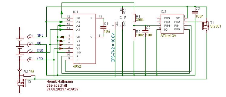
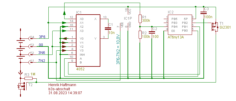
Schaltplan mit Mikrocontroller und Analogschalter
IC1 4052 IC2 ATtiny13A X0 X 12 13 14 15 11 1 5 2 4 6 10 9 Y 7 VEE 8 GND 16 VCC R1 300k R2 100k 100 C1 10n C2 100 C3 100n T1 Si2301 X4 3P6 X3 00 X2 3N6 X1 7N2 R3 1M T2 3P6-7N2 = 10.8V Henrik Haftmann b3s-abschalt 31.08.2023
in „Spannungsmessung an LIPO Akkus“ · Mikrocontroller und Digitale Elektronik · · Schaltpläne
-
Bild
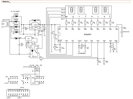
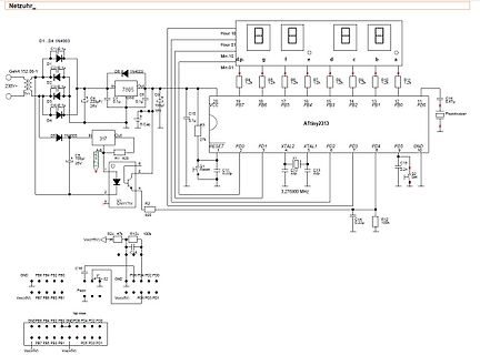
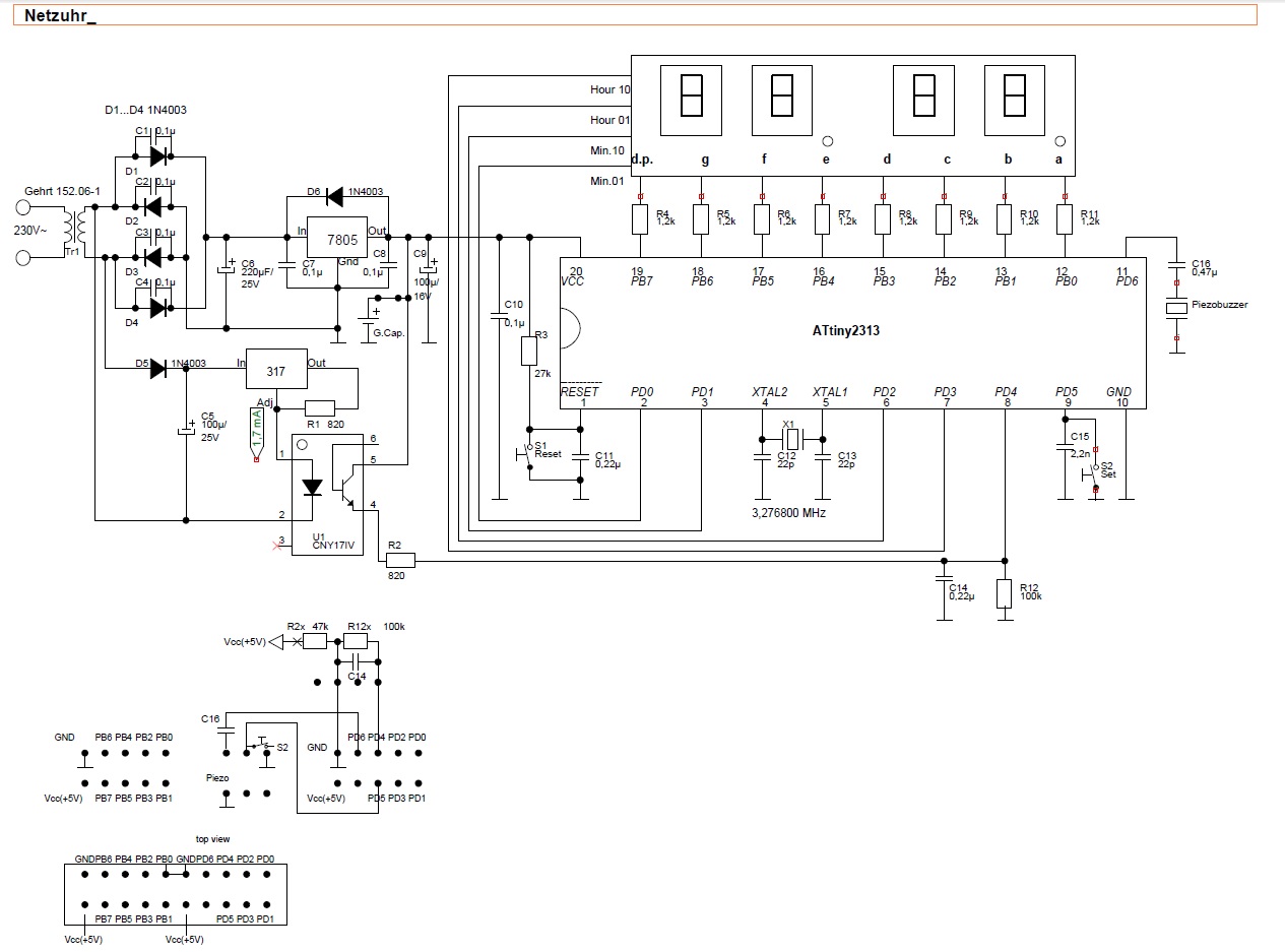
Schaltplan eines Netzteils mit ATtiny2313 und 7805
0.1uF, C2 100uF/25V, D5 1N4003, 317, R1 820, U1 LM317, 7805, C9 0.1uF, C10 100uF, R3 27k, RESET, C11 0.22uF, X1 3.276800 MHz, ATtiny2313, PB7 bis PB0, PD0 bis PD5, GND, C12 22pF, C13 22pF, C14 0.22uF, C15 0.22uF, R12 100k, R2x 47k, R12x 100k, Piezo buzzer
in „Reparaturtips für VFD von alter Elektronika-Leuchte“ · Analoge Elektronik und Schaltungstechnik · · Schaltpläne
-
Bild
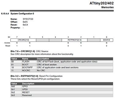
Registerbeschreibung System Configuration 0 für ATtiny202/402
ATtiny202/402 Memories 6.10.4.4 System Configuration 0 Name: SYSCFG0 Offset: 0x05 Reset: 0xC4 Property: - Bit 7 6 5 4 3 2 1 0 CRCRC[1:0] RSTPINCFG[1:0] EESAVE Access R R R Reset 1 1 0 1 0 Bits 7:6 – CRCRC
in „Attiny202 kein externer Reset“ · Mikrocontroller und Digitale Elektronik · · Screenshots
-
Bild
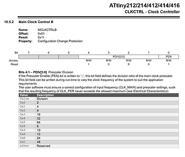
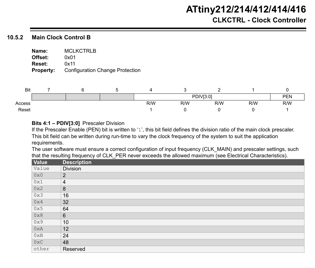
Datenblatt Ausschnitt ATtiny212/214/412/414/416 Clock Controller
ATtiny212/214/412/414/416 CLKCTRL - Clock Controller 10.5.2 Main Clock Control B Name: MCLKCTRLB Offset: 0x01 Reset: 0x11 Property: Configuration Change Protection Bit 7 6 5 4 3 2 1 0 Access R/W R/W R/W
in „ATTiny 412 OOK Modulation“ · Mikrocontroller und Digitale Elektronik · · Screenshots
-
Datei
USI_TWI_Master.c
Corporation * * File : USI_TWI_Master.c * Compiler : IAR EWAAVR 2.28a/3.10a * Revision : $Revision: 1.11 $ * Date : $Date: Tuesday, September 13, 2005 09:09:36 UTC $ * Updated by : $Author: jtyssoe $ * * Support mail : avr@atmel.com * * Supported devices : All device with USI module can be used. * The example is written for the ATmega169, ATtiny26 and ATtiny2313 * * AppNote : AVR310 - Using the USI module as a TWI Master * * Description : This is an implementation of an TWI master using * the USI module as basis. The implementation assumes
in „Butterfly USI als TWI Master verwenden“ · Mikrocontroller und Digitale Elektronik ·
-
Datei
ATTiny861_VGA_asm.bas
'Mini-VGA-Grafikkarte '-------------------- ' 'Mikrocontroller: ATTiny861 'Frequenz: 24,576 MHz 'PORTB.0 = HSync (über 1k Ohm an HSync) 'PORTB.1 = Monochromsignal (über 100 Ohm an R, G & B) 'PORTB.2 = VSync (über 1k Ohm an VSync) 'PORTA = Data 0 - 7 / Adr 0 - 7 'PORTB.3 = Adr 8 'PORTB.6 = WriteClk $regfile = "ATTiny861.dat" $crystal = 24576000 $hwstack = 8 $swstack = 0 $framesize = 8 Config Portb.0 = Output Config Portb.1 = Output Config Portb.2 = Output Config Portb.3 = Input Portb.3 = 1 Config Portb.6 = Input
in „EEPROM-lese-Routine "veräppelt" mich“ · Mikrocontroller und Digitale Elektronik ·
-
Datei
ATTiny861_VGA_asm.bas
'Mini-VGA-Grafikkarte '-------------------- ' 'Mikrocontroller: ATTiny861 'Frequenz: 24,576 MHz 'PORTB.0 = HSync 'PORTB.1 = Monochromsignal 'PORTB.2 = VSync $regfile = "ATTiny861.dat" $crystal = 24576000 $hwstack = 8 $swstack = 0 $framesize = 8 Config Portb.0 = Output
in „VGA-Grafikkarte - Fehler in der Routine zum Schreiben von Daten“ · Mikrocontroller und Digitale Elektronik ·
-
Datei
USI_TWI_Master.c
USI_TWI_Master.c * Compiler : AVRGCC Toolchain version 3.4.2 * Revision : $Revision: 992 $ * Date : $Date: 2013-11-07 $ * Updated by : $Author: Atmel $ * * Support mail : avr@atmel.com * * Supported devices : All device with USI module can be used. * The example is written for the ATmega169, ATtiny26 and ATtiny2313
in „C-Code optimieren (passt nicht in Attiny2313) :(“ · Mikrocontroller und Digitale Elektronik ·
-
Datei
USI_TWI_Master.c
File : USI_TWI_Master.c * Compiler : IAR EWAAVR * Revision : $Revision: 6.21.1 $ * Date : $Date: 2013-11-07 $ * Updated by : $Author: Atmel $ * * Support mail : avr@atmel.com * * Supported devices : All device with USI module can be used. * The example is written for the ATmega169, ATtiny26 and ATtiny2313
in „I2C ATtiny167 mit USI“ · Mikrocontroller und Digitale Elektronik ·
-
Datei
USI_TWI_Master.c
USI_TWI_Master.c * Compiler : AVRGCC Toolchain version 3.4.2 * Revision : $Revision: 992 $ * Date : $Date: 2013-11-07 $ * Updated by : $Author: Atmel $ * * Support mail : avr@atmel.com * * Supported devices : All device with USI module can be used. * The example is written for the ATmega169, ATtiny26 and ATtiny2313
in „TWI mit USI nach AN-310“ · Mikrocontroller und Digitale Elektronik ·
-
Bild
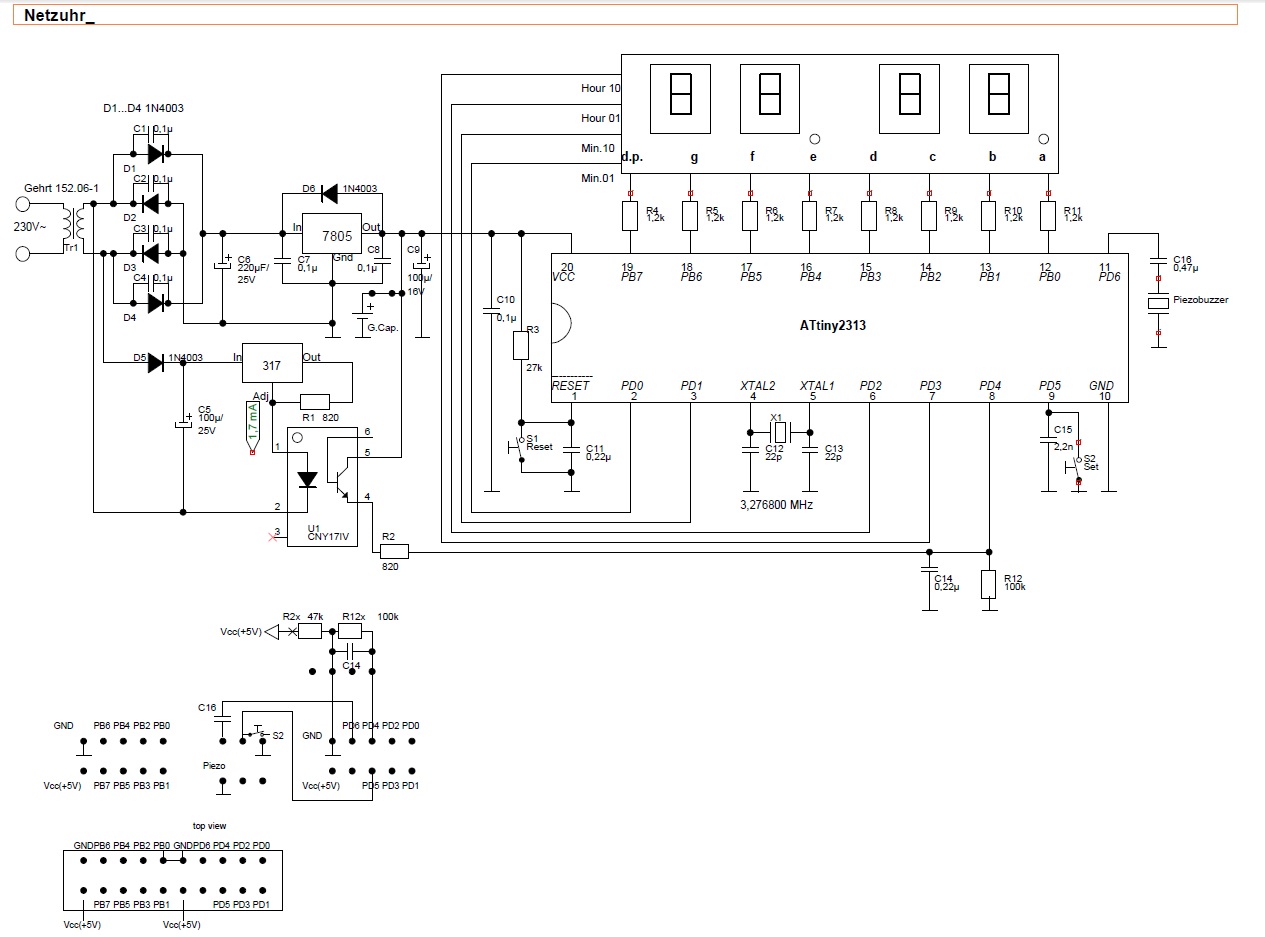
Schaltplan eines Netzteils mit ATtiny2313 Mikrocontroller
, 7805, C4 0.1uF, C5 100uF/25V, 317, R1 820, U1 LM317, R2 820, C6 0.1uF, RESET, X1 3.276800 MHz, ATtiny2313, R4 bis R11, C10 10uF, C12 22pF, C13 22pF, C14 0.22uF, C15 0.22uF, C16 0.47uF, Piezo buzzer, R12 100k, R2x 47k, R3 27k, Vcc(5V), GND
in „Reparaturtips für VFD von alter Elektronika-Leuchte“ · Analoge Elektronik und Schaltungstechnik · · Schaltpläne
-
Datei
dds.asm
* ; ;Description ; ; Poor-mans DDS Synthesizer ; ; Author = Jesper Hansen ; Target = AT90S2313 / ATTiny2313 ; Date = 2001-02-15 ; ; Code is written for use with AVR-GCC in assembler mode ; flag: -x assembler-with-cpp ; ; ; PB0..7 = D/A Data out ; ; PD0 RXD ; PD1 TXD ; PD2..6 not used ; ;*************
in „ASM von MiniDDS in WinAVR kompilieren. Wie?“ · Mikrocontroller und Digitale Elektronik ·
-
Datei
led.c
********* * * LED strip Steuerung mit IR * Andreas Brietzke, Nagareyama-shi, J * * * Chip type : ATtiny2313 * Clock frequency : 8 MHz * lfuse 64 = 0110 0000 -> a4 = 1010 0100 * hfuse df = 1101 1111 -> d9 = 1101 1001 * avrdude -p t2313 -c usbasp -B 10 -U lfuse:w:0xa4:m -U hfuse:w:0xd9:m * * led.c * *
in „ATtiny2313, gcc. unerklärliches Verhalten“ · Mikrocontroller und Digitale Elektronik ·
-
PDF
AvrBoard.pdf
RTS RS232 ^Reset 13 CTS 9 6 t d I 25 5 1 s n 5 C S S Gnd Reset e G + S I O Vcc 220 24 R M M (^Busy) 11 SCK 23 MISO 100n D PC6/ 2 220 22 x x 1Reset PC5 8 MOSI (Data7) 9 1 T R 8 2 21 1 6 2PD0 aPC47 220u (Data6) 8 1 e 2 20 2 5 3PD1 mPC36 (Data5) 7 1 A 2 19 100n 3 4 4PD2 PC25 (Data4) 6 2 1 2 18 4 2 3 5PD3
in „LED flackern“ · Mikrocontroller und Digitale Elektronik ·
-
PDF
AvrBoard__1_.pdf
RTS RS232 ^Reset 13 CTS 9 6 t d I 25 5 1 s n 5 C S S Gnd Reset e G + S I O Vcc 220 24 R M M (^Busy) 11 SCK 23 MISO 100n D PC6/ 2 220 22 x x 1Reset PC5 8 MOSI (Data7) 9 1 T R 8 2 21 1 6 2PD0 aPC47 220u (Data6) 8 1 e 2 20 2 5 3PD1 mPC36 (Data5) 7 1 A 2 19 100n 3 4 4PD2 PC25 (Data4) 6 2 1 2 18 4 2 3 5PD3
in „portpin PD.3 liefert kein signal“ · Mikrocontroller und Digitale Elektronik ·
-
PDF
Pollin_Geigerzaehler.pdf
Bestückungsplan Stückliste Stück Bauteil Wert/Bezeichnung Stück Bauteil Wert/Bezeichnung 1 R1 1 MΩ 1 C11 220 nF 1 R2 68 Ω 1 C13 47 µF 2 R3, R13 180 Ω 1 IC1 IRFDC20 1 R4 4,7 MΩ 1 IC2 MC34063 1 R5 820 kΩ 1 IC3 HEF40106 1 R6 560 kΩ 1 IC4 7805 2 R7, R8 1,5 kΩ 1 IC5 ATTINY2313 2 R9, R16 1 kΩ 1 Q1 BC547 1 R10 0,22 Ω 1 Q2 BC546 2 R11, R15 470 kΩ 1 Q3 8 MHz 1 R12 27 Ω 1 Q4 BC547 2 R14, R18 4,7 kΩ 1 L1 330 µH 1 R17 470 Ω 1 TR1 2,5 kΩ 1 R19 10 kΩ 1 TR2 10 kΩ 1 R20 2,2 kΩ 1 J1 Anschlussklemme 1 D1 1N4937 1 J2 Anschlussklemme 3 D2, D3
in „Pollin Geigerzähler Bericht“ · Mikrocontroller und Digitale Elektronik ·
-
Bild
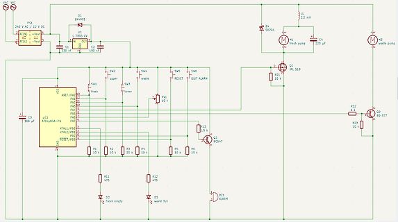
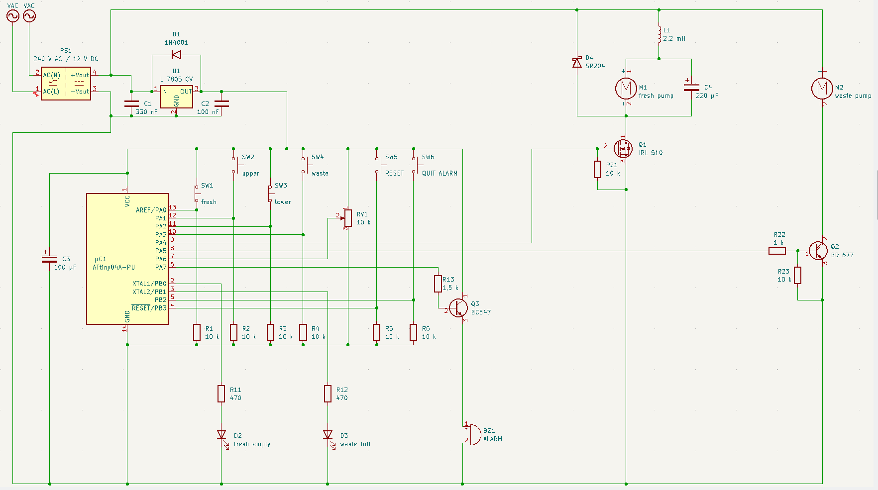
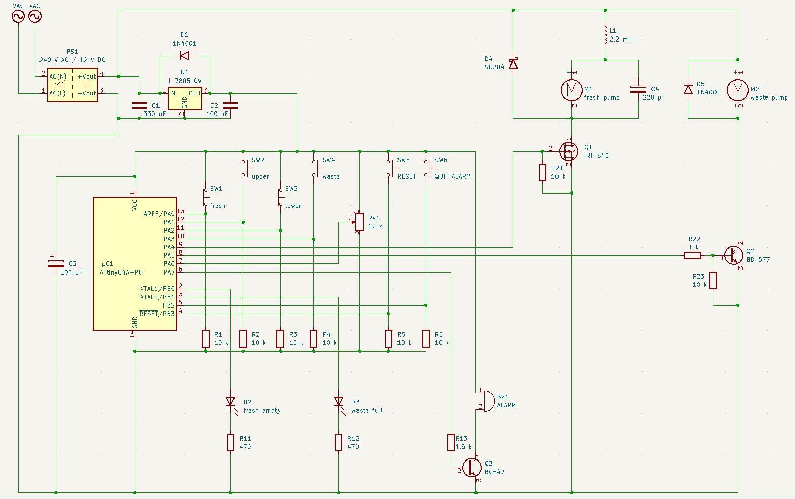
Schaltplan einer Pumpensteuerung mit Mikrocontroller
C2 100 nF M1 fresh pump M2 waste pump D4 SR204 Q1 IRL 510 R21 10 k R22 1 k Q2 BC 677 R23 10 k uC1 Attiny84A-PU RESET PB3 PB2 XTAL2/PB1 XTAL1/PB0 PA7 PA6 PA5 PA4 PA3 PA2 AREF/PA0 VCC SW1 upper SW2 lower SW3 waste SW4 fresh SW5 QUIT ALARM SW6 RESET RV1 10 k R1 10 k R2 10 k R3 10 k R4 10 k R5 10 k R6 10 k Q3 BC547 R11 470 R12 470 D2 fresh empty D3 waste full GND
in „DAC-Pumpensteuerung: 5V PWM --> 12 V analog“ · Analoge Elektronik und Schaltungstechnik · · Schaltpläne
-
Bild
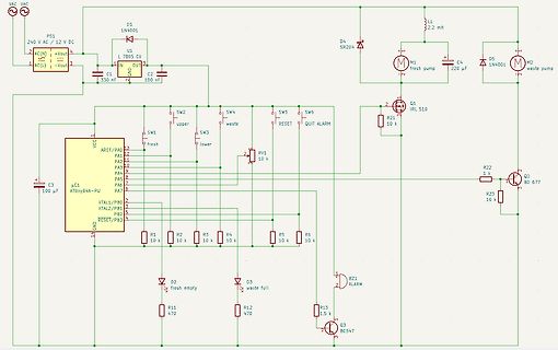
Schaltplan einer Pumpensteuerung mit ATtiny84A
fresh, SW3 lower, SW4 waste, SW5 RESET, SW6 QUIT ALARM, R22 1 k, Q2 BD 677, R23 10 k, RV1 10 k, uC1 ATtiny84A-PU, C3 100 uF, R1 10 k, R2 10 k, R3 10 k, R4 10 k, R5 10 k, R6 10 k, D2 fresh empty, D3 waste full, R11 470, R12 470, R13 1.5 k, Q3 BC547, BZ1 ALARM
in „DAC-Pumpensteuerung: 5V PWM --> 12 V analog“ · Analoge Elektronik und Schaltungstechnik · · Schaltpläne
-
Bild
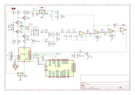
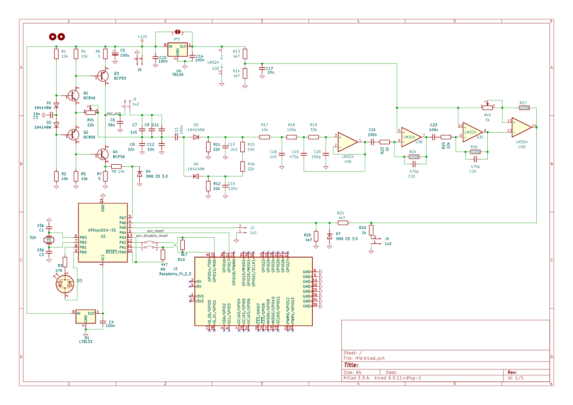
Schaltplan mit Raspberry Pi und Verstärkerschaltung
LM324, U3, R27, R2, R19, R24, C22, C24, R25, R22, R20, R26, R10, R9, R7, R5, R4, R1, R16, R15, R14, R11, R8, R6, R3, C10, C5, C7, C8, C12, C15, C16, C19, C20, C21, C22, C23, C24, Q1, Q2, Q3, D1, D2, D4, D5, D6, U2, ATtiny164-55, P3, P4, P1, P0, RESET/PA0, Raspberry_Pi_2_3, 3v3, 5v, GPIO0 bis GPIO13, J4
in „Bitte nicht nachmachen: PE des DSO abkleben?“ · Analoge Elektronik und Schaltungstechnik · · Schaltpläne
-
Datei
tiny13ifr.txt
'Infrotlichtschranke 'alter analoger Sat-Reciver liefert IFR-LED und TSOP1736 ' 'D.J. 30.11.2011 $regfile = "attiny13.dat" $crystal = 4800000 $hwstack = 10 $swstack = 10 $framesize = 32 '$sim '-------------------------------------------------------- Config Portb.0 = Output 'oca0a ifr_led Config
in „Infrarot-Näherungs-Schalter AuslöseProbleme“ · Mikrocontroller und Digitale Elektronik ·
-
Datei
encoder4.c
<avr/sleep.h> #include <avr/eeprom.h> #include <avr/pgmspace.h> #include <util/delay.h> // CPU: ATTiny44-20PU 8MHz // ======================================================================= // Ein-/Ausgänge // ----------------------------------------------------------------------- #define ENCODER_PORT
in „attiny13 aufwecken aus power down modus“ · Mikrocontroller und Digitale Elektronik ·
-
PDF
DN_047.pdf
51 5 Q 7 B t e 21 6 Q 6P 51 6 Q 41 A C n a 2 5P 41 7 Q 31 0 0 m c 4P 31 1 8 Q 21 F D g a 3P 4 9 11 G E s C 2P 5 t SQ 6 p 4 9 7 1P 7 I 7 0 SQ 01 SD 11 U 4 o t 42-71st u O 5 N KLC 01 + s 1 RTS 1 Q 4 2 S/ P R D 2 Q U 4 9 0 2 KLC 3 Q 5 8 Q 8P 1 3 EO 4 Q 6 3 7 Q 7P 1 51 5 Q 7 21 6 Q 6P 51 6 Q 41 2 5P 41 7 Q 31 2 4P 31 - 8 Q 21 E 2 3P 4 1 11 L 5 t 9 8 7 6 5 4 3 2 1 1 2P 6 p SQ 9 1P 7 I 8 9 SQ 01 SD 11 U 40 r D D D D D D D D C C o e 8 7 6 5 4 3 2 1 O t 23-52st u O i 5 e r KLC + s RTS 1 Q c 3 S/ P 01 R 1 D 2 Q 4 e 5 4 0 9 0 2 KLC 3 Q 5 l 0
in „AVR und I/O-Expander“ · Mikrocontroller und Digitale Elektronik ·
-
PDF
AVR042.pdf
are used for programming the Flash, EEPROM, Lock-bits and most Fuse-bits in all AVRs (except the ATtiny11 and ATtiny28). This feature makes it possible to program the AVR on the last stage of production of a target application board, reprogram if SW bugs are identified late in the process, or even update
in „Beschaltung MEGA128 mit ISP und UARD0“ · Mikrocontroller und Digitale Elektronik ·
-
PDF
AVR042.pdf
are used for programming the Flash, EEPROM, Lock-bits and most Fuse-bits in all AVRs (except the ATtiny11 and ATtiny28). This feature makes it possible to program the AVR on the last stage of production of a target application board, reprogram if SW bugs are identified late in the process, or even update
in „Widerstände an MISO und MOSI?“ · Mikrocontroller und Digitale Elektronik ·
-
PDF
doc2521.pdf
are used for programming the Flash, EEPROM, Lock-bits and most Fuse-bits in all AVRs (except the ATtiny11 and ATtiny28). This feature makes it possible to program the AVR on the last stage of production of a target application board, reprogram if SW bugs are identified late in the process, or even update
in „Quarz will nicht anschwingen Atmega8“ · Mikrocontroller und Digitale Elektronik ·
-
PDF
AVR042.pdf
are used for programming the Flash, EEPROM, Lock-bits and most Fuse-bits in all AVRs (except the ATtiny11 and ATtiny28). This feature makes it possible to program the AVR on the last stage of production of a target application board, reprogram if SW bugs are identified late in the process, or even update
in „Mein erstes Projekt“ · Mikrocontroller und Digitale Elektronik ·
-
PDF
AVR042.pdf
are used for programming the Flash, EEPROM, Lock-bits and most Fuse-bits in all AVRs (except the ATtiny11 and ATtiny28). This feature makes it possible to program the AVR on the last stage of production of a target application board, reprogram if SW bugs are identified late in the process, or even update
in „Programier leitungen doppelt nutzen“ · Mikrocontroller und Digitale Elektronik ·
-
PDF
AVR042-doc2521.pdf
are used for programming the Flash, EEPROM, Lock-bits and most Fuse-bits in all AVRs (except the ATtiny11 and ATtiny28). This feature makes it possible to program the AVR on the last stage of production of a target application board, reprogram if SW bugs are identified late in the process, or even update
in „Anfänger: Atmel 8 beschaltung ?“ · Mikrocontroller und Digitale Elektronik ·
-
Datei
tiny26Wahnsinn.txt
.include "tn26def.inc" .device Attiny26 .org $0000 rjmp Reset .def temp =r16 .def temp2 =r19 ; I/O Pins .equ Frequency_out =1 Reset: ; Stackpointer bis 265 Byte initialisieren ldi temp, RAMEND out SP, temp ;I/O Initialisierung ldi temp
in „pwm auf tiny26 - hilfääää“ · Mikrocontroller und Digitale Elektronik ·
-
Bild
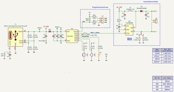
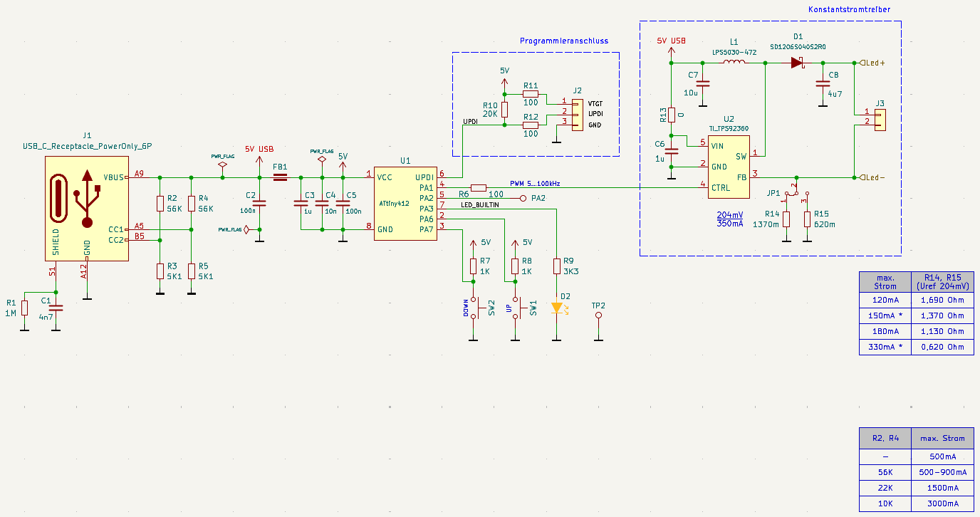
Schaltplan eines Mikrocontrollers mit USB-Anschluss und Konstantstromtreiber
6P A9 VBUS= R1 1M C1 4n7 A5 GND R2 56K A7 GND R3 5K A2 GND C2 100n F1 USB R4 5K A12 GND C3 1u U1 ATtiny412 1 VCC 2 UPDI 3 LPD1 4 PA1 5 PA2 6 PA3 7 PA6 8 PA7 R5 5K R6 100 PA2 R10 20K R11 100 R12 100 J2 1 2 3 GND 5V USB L1 LPS03030-472 C7 10u R13 1u U2 TPS2360 5 VIN 1 SW 2 GND 3 CTRL 4 FB 6 C5 5 C6 5 JP1
in „VIN am Konstantstromtreiber?“ · Analoge Elektronik und Schaltungstechnik · · Schaltpläne
-
Datei
Neu_Text_file.txt
R0X4=R4 .DEF R0X5=R5 .DEF R0X6=R6 .DEF R0X7=R7 .DEF R0X8=R8 .DEF R0X9=R9 .DEF R0XA=R10 .DEF R0XB=R11 .DEF R0XC=R12 .DEF R0XD=R13 .DEF R0XE=R14 .DEF R0XF=R15 .DEF R0X10=R16 .DEF R0X11=R17 .DEF R0X12=R18 .DEF R0X13=R19 .DEF R0X14=R20 .DEF R0X15=R21 .DEF R0X16=R22 .DEF R0X17=R23 .DEF R0X18=R24 .DEF R0X19
in „CodeVision Einsteiger“ · Mikrocontroller und Digitale Elektronik ·
-
Datei
main.c
--------------------------------------------------------------------- // File: main.c // Datum: 05.11.2013 // Autor: Roland Höck // CPU: ATtiny4313 // Funktion: Hauptprogramm //---------------------------------------------------------------------------------------------------- // ---------- Includes
in „RS485 geht nicht“ · Mikrocontroller und Digitale Elektronik ·
-
Datei
main.c
/* * ATtiny24A-Test.c * * Created: 27.03.2021 13:33:20 * Author : Micha */ #define F_CPU 8000000UL #define I2C_FAST_MODE #include <avr/io.h> #include <avr/interrupt.h> #include "USI_I2C_Master.c" volatile int16
in „USI_TWI_Master.c von Atmel“ · Mikrocontroller und Digitale Elektronik ·
-
Datei
diff-20100825.txt
2 lines +#define LCD_COLS 16 // 10col display (2*5) - only required for wrap #if defined (__AVR_ATtiny2313__) || defined (__AVR_ATtiny2313A__) @@ -265,6 +292,9 @@ extern int main (void) { uint8_t i; char buf[16]; + enum {FREQ_ID_HZ=0, FREQ_ID_KHZ, FREQ_ID_MHZ, FREQ_ID_GHZ}; + const char *a_freq_text
in „Reziproker Frequenzzähler+ Optimierte 64bit uint Routinen“ · Projekte & Code ·
-
Datei
Hysterese_4.asm
******************************************************************* ;* Hysterese_4.ASM ;* ;* Für ATtiny26 mit internen Kalibrierten RC-Oszilator von 1Mhz ;* ;* Eine Balkenanzeige aus acht LEDs soll acht Schwellwerte anzeigen. ;* Oberster Schwellwert ueberschritten bedeutet alle LEDs an. ;* Unterster

in „ATtiny26 Balkenanzeige ( Hysterese ) mit acht Schaltschwellen (ASM)“ · Projekte & Code ·
-
Datei
irsnd.c
Copyright (c) 2010-2015 Frank Meyer - frank(at)fli4l.de * * Supported AVR mikrocontrollers: * * ATtiny87, ATtiny167 * ATtiny45, ATtiny85 * ATtiny44 ATtiny84 * ATmega8, ATmega16, ATmega32 * ATmega162 * ATmega164, ATmega324, ATmega644, ATmega644P, ATmega1284, ATmega1284P * ATmega88, ATmega88P, ATmega168
in „IRMP - Infrared Multi Protocol Decoder“ · Projekte & Code ·
-
Datei
irsnd.c
Copyright (c) 2010-2015 Frank Meyer - frank(at)fli4l.de * * Supported AVR mikrocontrollers: * * ATtiny87, ATtiny167 * ATtiny45, ATtiny85 * ATtiny44 ATtiny84 * ATmega8, ATmega16, ATmega32 * ATmega162 * ATmega164, ATmega324, ATmega644, ATmega644P, ATmega1284, ATmega1284P * ATmega88, ATmega88P, ATmega168
in „IRMP - Infrared Multi Protocol Decoder“ · Projekte & Code ·