Amplifier Absolute Maximum Ratings Recommended Operating Conditions Parameter Rating Parameter Min Typ Max Units Storage Temperature −55 to +150 °C Device Voltage (VC) +4.75 +5 +5.25 V RF Input Power, CW, 50 Ω, T=25 °C +24 dBm T −55 +105 °C CASE Device Voltage (C ) +5.5 V Electrical specifications are measured
nicht. https://www.mcselec.com/index.php?option=com_content&task=category§ionid=7&id=79&Itemid=105&limit=5&limitstart=0 Naja, so viel Aufwand ist der AN204 auch nicht. Kann man ja einfach am Ende des Programms hinschieben... Grüße, Gerhard
zugehörige Link dazu: https://www.mcselec.com/index.php?option=com_content&task=view&id=367&Itemid=105 https://www.mikrocontroller.net/topic/568639?goto=7692236#7684443 Moin, wir haben Dich zum Wassertrog geführt. Das Trinken mußt schon Du selbst besorgen...
Nachtrag: Die Treibertransistoren sind Q105 und Q110. Was anderes ist nicht kräftig genug, um jeweils zwei Endtransistoren zu steuern. Die MOSFETs im Netzteil ignoriere erstmal. Bzw. Gibt es auf der 12V-Seite einen Kurzschluss zwischen +12V
> Labornetzteil habe ich, liefert aber max 2A was nicht gereicht > hat um die Endstufe einzuschalten. Die ist auf 7 volt runter > gefallen und die Endstufe hat nicht eingeschaltet. Normal wenn da defekte Endtransistoren drin sind. > Was
Michael B. schrieb im Beitrag #7679489: > ( 24000W / 230V = 105A ) / 3 = 35A Die 230V braucht man hier nicht, man kann gleich mit dem VErkettungsfaktor rechnen. [pre] 24.000 W / 400V / Wurzel(3) = 35A [/pre]
eben mit > 60 A. Dass ... glaube ich nicht. Sofern das dies ein Privathaushalt ist, wird meist max. 35 A abgesichert. Habe noch keinen Hausanschluss mit 63A gesehen.
as Phase-Change Mem- schemes can make them more vulnerable to manipulations that ory (PCM) [85, 98, 105, 113, 138]. PCM promises significant im- repeatedly write data to the same physical location. provements over flash in both bandwidth and endurance [91, 153]. The closest work to this paper, in terms
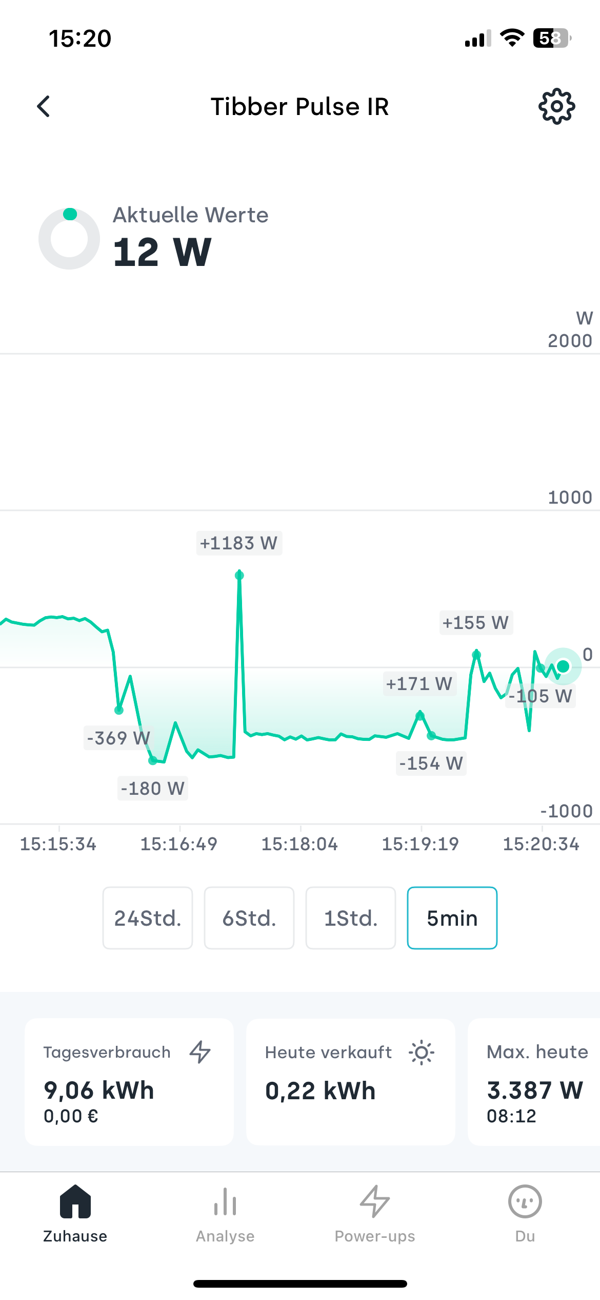
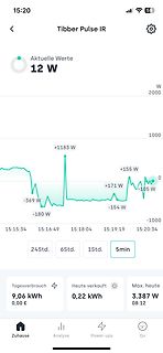
Werte 12 W W 2000 1000 +1183 W -369 W -180 W 15:15:34 15:16:49 15:18:04 15:19:19 15:20:34 +155 W -105 W 0 -154 W W 24Std. 6Std. 1Std. 5min Tagesverbrauch 9,06 kWh 0,00 € Heute verkauft 0,22 kWh Max. heute 3.387 W 08:12 Zuhause Analyse Power-ups Du
Characteristics (Test conditions unless otherwise specifiAd: -40°C < T < 85°C.) Sym Parameter Min Typ Max Units Conditions V - V Input to output voltage difference 12 - 450 V --- IN OUT 13.2V < V < 400V, 1.14 1.20 1.26 V IN VOUT Overall output voltage regulation R1= 2.4kΩ, R 2 0 375 400 425 V R = 2.4kΩ,
c) Schaltungen mit einer ähnlichen Sperrfunktion, die auf Ir, max der maximale Rück-(Lade-)Strom aus dem Produkt zwei oder mehr unabhängigen Schutzeinrichtungen beruht, katalog vorausgesetzt, die erste Schutzeinrichtung kann den Lade- strom durch die Lithiumbatterie
FULL-FEATURED FLYBACK REGULATOR ELECTRICAL CHARACTERISTICS VCC = 16V, T = -40°C to 125°C, min and max values are guaranteed by characterization, typical J values are tested under 25°C, unless otherwise noted. Parameter Symbol Conditions Min Typ Max Unit Start-Up Current Source (DRAIN) Drain_0 VCC =
6000 G R (α ≈ 5) 5000 T 1000 ST O 800 S 4000 V RE 3000 U (1") SQ (α ≅ 8) O 500 ) 2000 N 400 ( A G MAX N 300 A 1000 IMU T L 800 M V S 200 LITTELFUSEVARISTOR V 600 O T I SILICON POWER (20mm DIA.) D 500 AGE TRANSIENT SUPPRESSOR (α > 25) I 400 /s M NIM (ZENER) (α ≅ 35) P 300 k U MVO L 100 A 2 µs A GE 1
AAA Energizer Max (Singapore) AAA Energizer Max aus IR-FB gebr. MHD 12-2030 MHD 12-2030 Kauf 10-2020 Kauf 10-2020 17. Oktober 2021 15. Mai 2024 Entladung mit: 30 mA Entladung mit: 30 mA mAh max: 1197 mAh max: 1100 Time
ist wohl eine serielle Schnittstelle, schliess da mal einen Rechner an (ggf mit Pegelkonverter a la MAX232 etc) und starte ein Konsolen-Programm, beim Hochfahren sind da sicher interessante Sachen zu lesen
wohl eine serielle > Schnittstelle, schliess da mal einen Rechner an (ggf mit Pegelkonverter > a la MAX232 etc) Im NAS ist ein Pegelwanler. Ich habe ein USB-Serialkabel, aber was bedeutet der Anschlußname im Gerätemanager "THIS IS NOT PROFILIC PL2303, PLEASE CONTACT YOUR SUPPLIER." Win hat einen
to 5.5 V, TYP values at 25°C and 3.0 V. Oscillator Parameters: SYMBOL PARAMETER CONDITIONS MIN TYP MAX UNIT Xtal General F Crystal Frequency 32.768 kHz Oscillator start-up time at TA= 25°C 0.1 0.5 START VDD = 3.0 V T = -40 to +105°C 3 s A VSTART Oscillator start-up voltage TA= -40 to +105°C 1.3 V Frequency
sec)(meters) Length limiting faTyp.number limiting factor I C 400k 2 w iring capacitance 20 400pF max Speed of various connectivity methods (bits/sec) I Cw ith buffer 400k 100 propagation delays any no limit I Chigh speed 3.4M 0.5 w iring capacitance 5 100pF max CAN 1 wire 33k 100 total capacitance
generated when the CNT is equal to TOP. If TOP is updated to a value lower than CNT, upon reaching MAX, an OVF interrupt and event is generated, and the counter restarts from BOTTOM. Figure 22-3. Periodic Interrupt Mode CAPT MAX and Event) Request (Interrupt Request and Event) TOP CNT BOTTOM TOP changed
Dauer hängt davon ab, wie die Bauteile eingestuft sind, sowie von der Verpackungsart. Sie beträgt max. 79 Tage bei 40 °C oder 10 Tage bei 90 °C oder 96 Std. bei 125 °C.
nur" 10..20° mehr Temperatur raus, > wenn der den Inhalt bei 1 Bar Überdruck hält. Üblich sind max 0,8 bar Überdruck.
networks, servers, hubs, routers & switches [Note 1] Electrical Specifications Parameters Min. Typ. Max. Units Notes Frequency (fc) 32.768 kHz Operating Temperature Range -40 +105 °C See Options Storage Temperature Range -55 +105 °C Frequency Stability ∆f/o vs: Tolerance -2.5 +2.5 Reference to fc (at
TCXO OPERATING CONDITIONS / ELECTRICAL CHARACTERISTICS PARAMETERS CONDITIONS ECS-327TXO UNITS MIN TYP MAX Frequency 32.768 KHz Frequency Tolerance @25°C ±3°C ±1.5 ppm Frequency Stability over Temp -40 ~ +85°C ±5 ppm Stability vs. Aging First Year at +25°C ±3 ppm Stability DD.Change ±5% VDD Change ±0.2 ppm
-Treiber-Elektronik die Sende-Stufe mit einer Art Tristate-Modus abschalten können. Beim bekannten MAX232 geht das leider nicht, dafür aber bei den Typen ICL3321 und MAX242. Tx: cmd arg0 arg1 ... argX/n Rx: cmd arg0 arg1 ... argX/n Beide verfügen über Low-Power-Shut- replyline1/n down-Modi, die sogar
, Rt. Hand Decimal. Electrical / Optical Characteristics at T A =25°C Symbol Parameter Device Typ. Max. Units Test Conditions λpeak Peak Wavelength High Efficiency Red 627 nm F=20mA Dominant Wavelength High Efficiency Red 625 nm F=20mA λD ∆λ1/2 Spectral Line Half-width High Efficiency Red 45 nm F=20mA
16%20MHz&frequency%20stability=-%20170%20PPM%20to%20%2B%2010%20PPM~~10%20PPM&supply%20voltage%20-%20max=1.01%20V~~3.3%20V&sort=pricing&rp=passive-components%2Ffrequency-control-timing-devices%2Foscillators%7C~Frequency%20Stability%7C~Supply%20Voltage%20-%20Max) Wenn es keine Rolle spielt dass man dafür
Epson TG2520SMN: Frequency tolerance +-1,5x10⁻⁶ Frequency / temperature characteristics +-0,5x10⁻⁶ Max / -40°C to +85°C Frequency / load coefficient +-0,1x10⁻⁶ Max / 10 kOhm 10 pF Frequency / voltage coefficient +-0,1x10⁻⁶ Max / Vcc+-5% Frequency aging +-0,5x10⁻⁶ Max +-0,5x10⁻⁶ ist sogar 8-stellig
Temperature Range ET series Bi-polarized series for operations over wide temperature range of –55 ~ +105 °C. Adapted to the RoHS directive (2002/95/EC). ET High Temperature VP Specifications Item Performance Characteristics Category TemperatureRange –55 ~ +105°C RatedVoltage Range 6.3 ~ 100V RatedCapacitance
Betreff genannten Elko. Bis 220 uf kein Problem zu finden. 330 oder 470 uF wären cool. Durchmesser max. 10 mm und Höhe Max. 14 mm. Jemand Ideen oder quellen? Dankeschön
rein gehen, da etwas Höhenreserve bis 14mm da ist: https://www.reichelt.de/elko-radial-330-f-35v-105-c-low-esr-fr-a-330u-35-p200285.html?search=fra+330 In vielen Fällen kommt es weniger auf die Kapazität, als auf den ESR an! 470/35 D10 H12,5 aber auch RM5 https://www.digikey.de/de/products/detail
was Du nicht überschreiten darfst, ist die Gesamtverlustleistung, je nach Ausentemperatur (bzw. die max. Chiptemperatur).
Die MX1 und MX2 Ausgänge können auch ohne Treiber benutzt werden, sofern der max. Strom von 110mA nicht überschritten wird. Das reicht also zum Muxen der beiden 7-Segment.
. Wenn das bei Deiner Netzwerkkarte nicht einzustellen geht, dann probiere es mit einer Karte, die max 100 MBit/s kann.
Alex B. schrieb im Beitrag #7643557: > Sebastian W. schrieb: >> Netgear GS105E oder GS108E > > Klasse! Danke für die konkreten Empfehlungen. Wahrscheinlich wird es auf > diese Lösung hinauslaufen. Achte drauf, dass es auch wirklich die "managed" Variante ist. Die GS105
gibt aber auch >20 € Datenblatt: https://docs.rs-online.com/7d49/A700000007842085.pdf Temperatur max. +150°C Öffnungstemperatur 120°C Schließtemperatur 105°C Also der heizt bis 120° erreicht sind, schaltet dann ab bis durch Abkühlen 105° unterschritten werden. Die Temperatursicherung ist übrigens
DIGITAL I/O EXTERNAL TRIGGER SENSING INPUT LOCAL OUTPUT REMOTE LINE RATING FUSE 50-60 Hz AC, 80 VA MAX LINE VOLTAGE SELECTED 90-110V 180-220V 105-125V 210-250V SLOWBLOW 3/4A 90-125V MADE IN 3/8A 100/250V KEITHLEY U.S.A. Figure 2-1. Model 230 Front and Rear Panel Controls and Connections 2-2 1. Press
(SC-59, aehnlich SOT23) 2SC4116 (SC-70 = SOT323) 2SC4738 (SC-75 = SOT416/SOT490) 2SC6026MFV (SC-105 = SOT723)[/c] Aber achte darauf, dass sie tatsächlich von Toshiba hergestellt wurden. Diese relativ konstante Stromverstärkung ist nach meiner Erfahrung aber sehr selten notwendig. Bernhard
als > Emitterfolger, mehr als 10V kann da nicht rauskommen. > D102, D103 klippen zum Schluß auf max 1,4V. Doch Tatsälich schon. Wo hast du die 20V max. her? Die 48V werden von einem 30V Trafo versorgt. Der Ausgang soll zwischen +- 30V eingestellt werden. Ausgelegt ist er auf max +-50V wenn ich
Effizienz ankommt. Gibt es eine ausführliche Tabelle zum Vergleichen von Spannungsregler mit; min. & max. Vin Mindestspannungsabfall max. Strom Leerlaufstrom ? Die hier auf mikrocontroller.net hat mir nicht so gut gefallen. Viele Grüße Charly
Max B. schrieb im Beitrag #7639616: > warum sich so > eine Fälschung lohnt? Du kennst die Löhne in China?
LO Local Oscillator SOP Small Outline Package LPOSC Low Power Oscillator SPI Serial Port Interface Max Maximum TH Threshold MCU Microcontroller Unit Tx Transmission, Transmitter Min Minimum Typ Typical MOQ Minimum Order Quantity VCO Voltage Controlled Oscillator NP0 Negative-Positive-Zero XOSC Crystal
stress ratings only and functional device operation is not implied. THERMAL DATA PARAMETER SYMBOL MAX UNIT SOT-223 180 °С/W Junction to Ambient SOT-23/SOT-89 θJA 400 °С/W TO-92 200 °С/W ELECTRICAL CHARACTERISTICS (TJ=25°С, unless otherwise stated) PARAMETER SYMBOL TEST CONDITIONS MIN TYP MAX UNIT
invertierender Verstärker mit dem TL072 104 12.5.2. Ein nicht umkehrender Verstärker mit dem TL072 105 13. Siebtes Projekt: DC-DC-Konverter 106 13.1. Bereitstellung des Power-MOSFETs 106 13.2. Der Step-Up-Konverter ( = Aufwärtswandler) 107 13.3. Der Flyback-Konverter ( = Sperrwandler) 109 13.4. Der Step-Down-Konverter
hab ein Solarpanel geschenkt bekommen (Solara S420M36 Ultra) Systemspannung: 12V Nennleistung STC: 105Wp Spannung bei Maximalleistung: 19,80V Leerlaufspannung: 23,40V Strom bei Maximalleistung: 5,30A Kurzschlusstrom: 5,90A Ertrag Max: 420Wh/d zudem hab ich für wenige Euro eine XLayer Mobile Powerstation
das meßtechnisch am Kühlsystem erfassen könnte. Denn da hat das Kühlwasser standardmäßig z.B. 105°, was für eigentlich alles im Motor und Motorraum die Obergrenze ist. Wird dann Leistung abgefordert, ist keine Luft mehr nach oben, sondern der Thermostat macht elektrisch beheizt voll auf. Dann hat
mechanische Lüfter dreht aber immer mit - wenn auch verringert durch die thermo Kupplung die auch die max Drehzahl begrenzt. Oder der Motor ist kalt, man starte und hört erst mal nur den lauten Lüfter. Obwohl dieser garnicht gebraucht wird. Mit einem elektronischen Lüfter kann der Luftstrom je nach Bedarf
to max. speed) 10 s Table 11: startup behavior 12 Supply Voltage Parameters Min. Typ. Max. Unit Nominal supply voltage 12 V Operating supply voltage range 9.0 16.0 V (measured at Drive connector) Supply voltage
(unless otherwise noted) DD PARAMETER TEST CONDITIONS † TLC252_C TLC25L2_C TLC25M2_C UNIT MIN TYP MAX MIN TYP MAX MIN TYP MAX 25°C 10 10 10 TLC25_2C 0°C to 12 12 12 70°C 25°C 5 5 5 Input VO = 0.2 , VIO offset TLC25_2AC R = 50 Ω 0°C to mV voltage S 70°C 6.5 6.5 6.5 25°C 2 2 2 TLC25_2BC 0°C to 3 3 3 70
2013 www.ixys.com PBNSMPD_1_0 SMPD Power MOSFETs Summary Table V I R DS(on) C Q R Part DSS D(cont) max iss g trr PD thJC Package Number max TC=25°C T=25°C typ typ (ns) (W) max Style (V) (A) J (pF) (nC) (°C/W) (Ω) TM TM TrenchT2 GigaMOS MMIX1T600N04T2 40 600 0.0013 40000 590 100 830 0.18 SMPD-X MMIX1T550N055T2
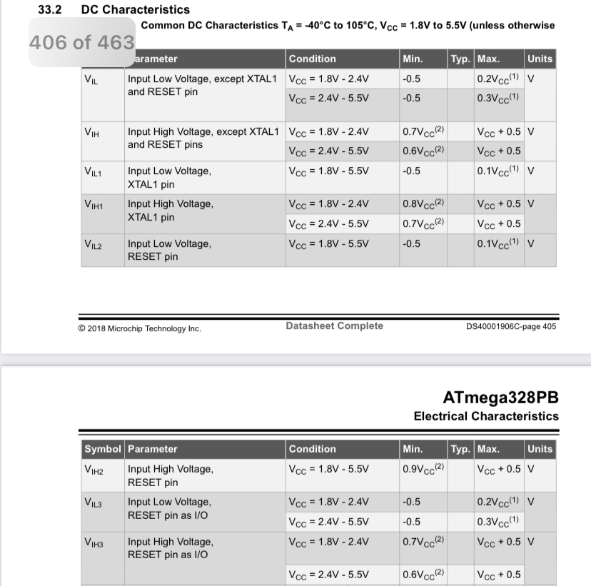
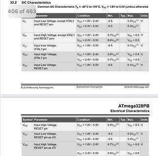
DC Characteristics
Common DC Characteristics TA = -40°C to 105°C, VCC = 1.8V to 5.5V
406 of 463
Parameter Condition Min. Typ. Max. Units
VIL Input Low Voltage, except XTAL1 and RESET pin VCC = 1.8V - 2.4V -0.5 0.2VCC(1) V
VCC = 2.4V - 5.5V -0.5 0.3VCC(1) V
VIH
Fuer 70 Eu bekommst du bei Max&Max immerhin 70 allerbeste "Pruefleitungen" in div. Laengen und Farben. (1000 V & 32 A) Fuer Messungen am Netz empfiehlt sich der "Energiekostenschaetzer" aus dem Supermarkt. Und zum "behoerdlichen
#7626847: > sind 70 Euro eine durchaus sehr mutige Ansage. Naja. Die Original-Gossen-Sonde kostet ~105€ neu. Wenn man sagt, man bekommt die Sonde für 70 und den Rest geschenkt, ist es "okay".
supply) of the connector can be used to supply power to the target hardware. Supply voltage is 5V, max. current is 300mA. The output current is monitored and protected againts overload and short-circuit. There are also other JTAG connectors in use. This includes: 20 pin JTAG version with 2mm pin pitch
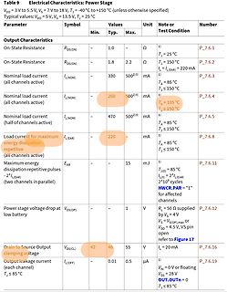
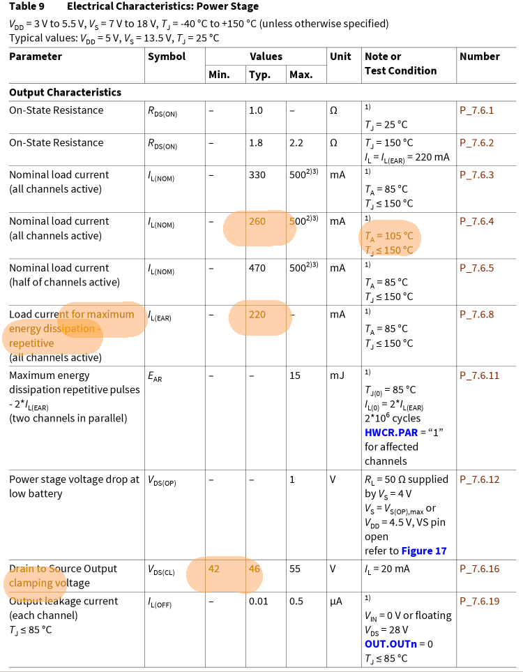
= 85 °C TJ ≤ 150 °C P_7.6.3
Nominal load current (all channels active) IL(NOM) 260 500(2) mA TA = 105 °C TJ ≤ 150 °C P_7.6.4
Nominal load current (half of channels active) IL(NOM) 470 500(2) mA TA = 85 °C TJ ≤ 150 °C P_7.6.5
Load current for maximum energy dissipation - repetitive (all channels active

 Bild
Bild
 Bild
Bild
 Bild
Bild