-
PDF
ttester.pdf
40 / t 38 a a C 36 34 32 0 1 2 3 4 5 6 7 8 9 10 11 12 13 14 15 16 Processor number Abbildung 5.60: Selbsttest: Nullwert der Kapazitätsmessung 80 REF_R_KORR 60 V m 40 / o c 20 r c 0 e t o -20 V -40 -60 0 1 2 3 4 5 6 7 8 9 10
in „Sammelbestellung Transistortester III - schnelle Runde“ · Markt ·
-
Datei
Fastboot.asm
0517 939C 0A2E '....7.....I.....' ret ; 0518 9508 0A30 '..7.....I.......' sbi ?0x06?, 7 ; 0519 9A37 0A32 '7.....I.........' ldi r24, 0x14 ; 051A E184 0A34 '....I...........' ldi r25, 0x00 ; 051B E090 0A36 '..I.............' rcall avr0666 ; 051C D149 0A38 'I...............' ldi r24, 0x00 ; 051D E080 0A3A
in „32 kHz kompatibler Bootloader gesucht“ · Mikrocontroller und Digitale Elektronik ·
-
PDF
Timer_-_AVR-AN130.pdf
pending interrupts ldi r16,1<<OCIE2 out TIMSK,r16 ; Enable timer output compare interrupt ldi r16,32 out OCR2,r16 ; Set output compare value to 32 ser r16 out DDRB,r16 ; Set Port D as output loop: sbic ASSR, OCR2UB ; Wait for registers to update rjmp loop ret 12 AVR130 2505A–AVR–02/02 AVR130 The corresponding
in „Timererklärung“ · Mikrocontroller und Digitale Elektronik ·
-
Datei
atue2.c
51,51,50,50,49,49,48,48,47,47, 46,46,45,44,43,43,42,42,41,41, 40,39,38,38,37,37,36,36,35,35, 34,34,33,33,32,31,31,30,30,29, 28,28,27,26,26,25,24,23,23,22, 22,21,21,20,20,19,19,18,18,17, 17,16,16,15,15,14,14,13,13,12, 12,11,11,11,10,10, 9, 9, 8, 8, 7, 7, 6, 6, 5, 5, 4, 4, 3, 3, 3, 2, 1, 0,-1,-2,-4,-4,-5,-5, -5,-6,-7,-7,-8,-9,-10,-11,-11,-12, -12,-12,-13,-14,-15,-16,-17,-18,-19,-20, -21,-22,-23,-24,-25,-26,-27,-28.-29,-30, -31,-32,-33,-34,-35,-36,-37,-38,-39,-40, -41,-42,-43,-44,-45,-46,-47,-48,-49,-50, -51,-52,-53,-54,-55,-56,-57,-58,-59,-60, -61,-62,-63
in „Array nach Interrupt auslesen“ · Mikrocontroller und Digitale Elektronik ·
-
Datei
atue2.c
51,51,50,50,49,49,48,48,47,47, 46,46,45,44,43,43,42,42,41,41, 40,39,38,38,37,37,36,36,35,35, 34,34,33,33,32,31,31,30,30,29, 28,28,27,26,26,25,24,23,23,22, 22,21,21,20,20,19,19,18,18,17, 17,16,16,15,15,14,14,13,13,12, 12,11,11,11,10,10, 9, 9, 8, 8, 7, 7, 6, 6, 5, 5, 4, 4, 3, 3, 3, 2, 1, 0,-1,-2,-4,-4,-5,-5, -5,-6,-7,-7,-8,-9,-10,-11,-11,-12, -12,-12,-13,-14,-15,-16,-17,-18,-19,-20, -21,-22,-23,-24,-25,-26,-27,-28.-29,-30, -31,-32,-33,-34,-35,-36,-37,-38,-39,-40, -41,-42,-43,-44,-45,-46,-47,-48,-49,-50, -51,-52,-53,-54,-55,-56,-57,-58,-59,-60, -61,-62,-63
in „Array nach Interrupt auslesen“ · Mikrocontroller und Digitale Elektronik ·
-
Datei
iotn2313.h
<avr/io.h> instead of this file." #endif #ifndef _AVR_IOXXX_H_ # define _AVR_IOXXX_H_ "iotn2313.h" #else # error "Attempt to include more than one <avr/ioXXX.h> file." #endif /* I/O registers */ /* * The
in „ATtiny2313 Timer0 problem“ · Mikrocontroller und Digitale Elektronik ·
-
PDF
catalog.pdf
-SSU [ID]: 000147 [Price]: 1.38 USD [QTY]: 5 [Category]: Microcontrollers [Desc]: MCU 8-bit ATtiny AVR CISC 8KB Flash 1.8V/2.5V/3.3V/5V 14-Pin Page 50/87 Bauteileliste vom 12.08.2022 SOIC W Tray MPN: STM32L151CBU6A [ID]: 000148 [Price]: 4.79 USD [QTY]: 4 [Category]: Microcontrollers [Desc]: Ultra-low-power ARM Cortex-M3 MCU with 128 Kbytes Flash, 32 MHz CPU, USB MPN: STM32F407VGT6 [ID]: 000149 [Price]: 14.66 USD [QTY]: 2 [Category]: Microcontrollers [Desc]: MCU 32-bit STM32F ARM Cortex M4F RISC 1024KB Flash 2.5V/3.3V 100-Pin LQFP Tray MPN: ATMEGA8
-
PDF
catalog.pdf
-SSU [ID]: 000147 [Price]: 1.38 USD [QTY]: 5 [Category]: Microcontrollers [Desc]: MCU 8-bit ATtiny AVR CISC 8KB Flash 1.8V/2.5V/3.3V/5V 14-Pin SOIC W Tray MPN: STM32L151CBU6A [ID]: 000148 [Price]: 4.79 USD [QTY]: 4 [Category]: Microcontrollers [Desc]: Ultra-low-power ARM Cortex-M3 MCU with 128 Kbytes Flash, 32 MHz CPU, USB MPN: STM32F407VGT6 [ID]: 000149 [Price]: 14.66 USD [QTY]: 2 [Category]: Microcontrollers [Desc]: MCU 32-bit STM32F ARM Cortex M4F RISC 1024KB Flash 2.5V/3.3V 100-Pin LQFP Tray MPN: ATMEGA8
-
 Bild
Bild
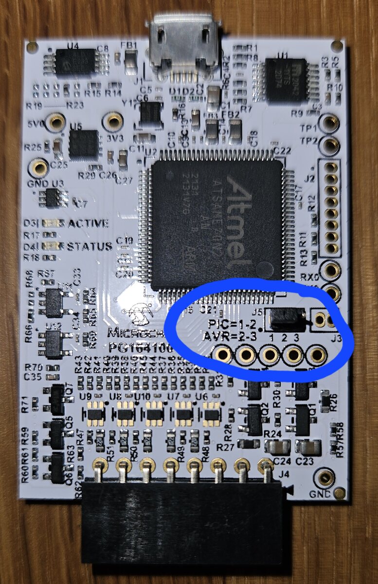
Bestückte Leiterplatte mit Atmel Mikrocontroller
U4 C8 FB1 R1 U1 R15 R14 C5 C6 D1 D2 R9 R10 R5 3V3 U5 C10 C11 C22 J2 R12 R11 R13 RX0 J3 PIC1-2 AVR=2-3 1 2 3 J3 ACTIVE STATUS C19 R18 R17 D31 R25 C25 R29 C26 U3 GND R68 R66 R60 C33 R63 R65 R64 R43 R42 R39 R38 R37 R36 R35 R34
in „[V] Microchip Snap (neue Version) mit Atmel Adapter“ · Markt · · Platinenfotos
-
PDF
HausAutoTest.pdf
XC6206P332MR LED S 8 CAN_L 4 5 CAP1 CAP2 8 R 3 VIN VOUT 2 3V3 2 1 GNDA FB ON/OFF 1 R 6 S 9 C9 U2 100uF D S C32 S C34 D9 S 330uF 1 V LED 0 U11 2 1 R JP2 2 R 100nF E D,4V Kerko 1 1uF Kerko C4GND 1 5 R L 20mA D7 R25 1 2 7 2 LED 100n 2 1 JUMPER D8 GND U17 1ULN2803 11 LED 1 18 10 2 1 14 SER QA 15 1B M 1C R 1 2 2B
in „Layout prüfen“ · Platinen ·
-
Datei
main.c
Zeichensatz für LCD // ===================================== const char PfeilL[] PROGMEM = {2 ,6 ,14,30,14,6 ,2 ,0}; // Pfeil Links const char PfeilR[] PROGMEM = {8 ,12,14,15,14,12,8 ,0}; // Pfeil Rechts const char BalkenLL[] PROGMEM = {1 ,1 ,1 ,1 ,1 ,1 ,1 ,0}; // Balken Links Leer const char BalkenRL[] PROGMEM = {16,16,16,16,16,16,16,0}; // Balken Rechts Leer const char KugelL[] PROGMEM = {0 ,14,17,17,17,14,0 ,0}; // Kugel Leer const char KugelV[] PROGMEM = {0 ,14,31,31,31,14,0 ,0}; // Kugel Voll const char BalkenL[] PROGMEM = {31,0 ,0 ,0 ,0 ,0 ,31,0}; // Balken Leer const char BalkenV[] PROGMEM
in „DOGM Eigener Zeichensatz“ · Mikrocontroller und Digitale Elektronik ·
-
PDF
_Dokumentation_V1.7_Stand_27.02.2013.pdf
************************* '* Programmfunktion : 10x10x10 LED-Cube * '* Programmieradapter : ICprog-AVR 2.0 (ISP) * '* Board : LED-Cube Controllerboard * '* Controller : ATMega32 * '* Taktquelle : XTAL * '* Taktfrequenz : 16000000 Hz * '* Code Version : 1.6 * '* Schaltplanversion : * '* Programmiersprache
in „Tutorial 10x10x10 LED-Cube“ · Mikrocontroller und Digitale Elektronik ·
-
PDF
_Dokumentation_V1.8_Stand_27.03.2013.pdf
Prototyp ist und ich einige Fehler erst im Betrieb feststellte. Im Layout wurden alle Fehler berichtigt. 32 Software Zum Programmieren des ATMega’s hab ich den ISP von IN-CIRCUIT (www.ic-board.de). Und zwar den Programmieradapter „ICprog-AVR2.0“ . Hier der Direktlink: http://www.ic- board.de/product_info.php
in „Tutorial 10x10x10 LED-Cube“ · Mikrocontroller und Digitale Elektronik ·
-
PDF
_Dokumentation_V1.9_Stand_23.09.2013.pdf
Prototyp ist und ich einige Fehler erst im Betrieb feststellte. Im Layout wurden alle Fehler berichtigt. 32 Software Zum Programmieren des ATMega’s hab ich den ISP von IN-CIRCUIT (www.ic-board.de). Und zwar den Programmieradapter „ICprog-AVR2.0“ . Hier der Direktlink: http://www.ic- board.de/product_info.php
in „Tutorial 10x10x10 LED-Cube“ · Mikrocontroller und Digitale Elektronik ·
-
Datei
avr910_2313_v38c.asm
---------+-------+-------+-----+------| ;* | New Commands since Version 3.3 | | | | | | ;* | Exit (AVR109, Bootloader) | 'E'(0x45) | | | 13d | 15 | ;* | Return Chip ID (Terminalmode only)| 'i'(0x69) | | s[n] | | 14 | ;* +-----------------------------------+-----------+-------+-------+-----+------+ ;*
in „Programmer incl. neuem Code für Atmel AN910“ · Projekte & Code ·
-
Datei
header.h
unsigned short // uint32_t | 32 | 0...2^32-1 | unsigned long // uint64_t | 64 | 0...2^64-1 | unsigned double oder unsigned long long #ifndef F_CPU #warning "F_CPU war noch nicht definiert, wird nun nachgeholt" #define F_CPU
in „Falscher RETURN-Wert (Atmega128)“ · Mikrocontroller und Digitale Elektronik ·
-
Datei
partlist.txt
DO35-10 diode (66.675 49.53) R0 IC2 AT24C512 DIL08 atmel (24.13 38.1) R0 IC3 MEGA48/88/168-AU TQFP32-08 avr-7 (39.37 20.32) R0 IC4 PCF8574T SO16W micro-philips (78.74 40.64) R180 IC6 LP2950CDT-3.3 DPACK v-reg (53.34 58.42) R90 IC7 HM51W17805 SOJ28-4 AMESYS (57.15 20.32) R180 IC8 FT232RL SSOP28 ftdichip
in „CP/M auf ATmega88“ · Mikrocontroller und Digitale Elektronik ·
-
Datei
mpx_8digit.h
8 MHz Takt intern Fuses: LO-> 0xE2 / HI-> 0xdf / EX-> 0xFF IDE : keine (Editor / make) Toolchain : AVR-GCC 31.01.22 by R. Seelig -------------------------------------------------- */ #ifndef in_mpx8 #define in_mpx8 #include <avr/io.h> #include <util/delay.h> #include <avr/pgmspace.h> #include <avr/interrupt.h
in „AVR-ATmega: Multiplex von 8 Digits 7-Segment und 8 Tasten“ · Projekte & Code ·
-
PDF
ttester_ger109k.pdf
40 / t 38 a a C 36 34 32 0 1 2 3 4 5 6 7 8 9 10 11 12 13 14 15 16 Processor number Abbildung 5.60: Selbsttest: Nullwert der Kapazitätsmessung 80 REF_R_KORR 60 V m 40 / o c 20 r c 0 e t o -20 V -40 -60 0 1 2 3 4 5 6 7 8 9 10
in „Sammelbestellung Transistortester III - schnelle Runde“ · Markt ·
-
Datei
spi_send.c
: http://www.atmel.com \n * Support email: avr@atmel.com * * $Revision: 763 $ * $Date: 2007-11-06 14:51:56 +0100 (ti, 06 nov 2007) $ \n * * Copyright (c) 2008, Atmel Corporation All rights reserved. * * Redistribution and use in source and binary
in „AVR Xmega USART DMA“ · Mikrocontroller und Digitale Elektronik ·
-
Datei
sdram_error.c
/* * sdram_error.c * * Created: 04.03.2016 14:14:30 * Author: Falk */ /* * sdram.c * * Created: 14.12.2014 22:43:03 * Author: Falk */ #include <avr/io.h> #include <avr/pgmspace.h> #include <string.h> #include <stdio.h> #define PRINT(string, ...)
in „Compilerfehler?“ · Mikrocontroller und Digitale Elektronik ·
-
Datei
owdevice_ATT13_DS18B20.c
/* * owdevice.c * * Created: 24.01.2012 14:11:43 * Author: Tobias Mueller, mail(at)tobynet.de */ #include <avr/io.h> #include <avr/interrupt.h> #ifdef __AVR_ATmega32__ #include "uart.h" #include <util/delay.h> #endif //DEVICES #ifdef __AVR_ATtiny13A
in „1-Wire Slave auf AVR“ · Mikrocontroller und Digitale Elektronik ·
-
Datei
arial8.h
, // 39 0x7E, 0x81, // 40 0x81, 0x7E, // 41 0x22, 0x14, 0x3E, 0x14, 0x22, // 42 0x08, 0x3E, 0x08, // 43 0xE0, // 44 0x08, 0x08, 0x08, // 45 0x20, // 46 0x70, 0x0C, 0x07, // 47 0x3E, 0x41, 0x41, 0x3E, // 48 0x02, 0x7F, // 49 0x62, 0x51, 0x49, 0x46, // 50
-
Datei
arial8.h
, // 39 0x7E, 0x81, // 40 0x81, 0x7E, // 41 0x22, 0x14, 0x3E, 0x14, 0x22, // 42 0x08, 0x3E, 0x08, // 43 0xE0, // 44 0x08, 0x08, 0x08, // 45 0x20, // 46 0x70, 0x0C, 0x07, // 47 0x3E, 0x41, 0x41, 0x3E, // 48 0x02, 0x7F, // 49 0x62, 0x51, 0x49, 0x46, // 50
in „KS 0108 - ein alter Bekannter - neu aufgelegt“ · Projekte & Code ·
-
PDF
FacharbeitsDocument.pdf
Typ und von der zum Einsatz gebrachten Programmiersprache ab ( vgl. Programming an Customizing the AVR Micro-controller, § 1.1 ). 12 13 2.4.1 AVR-Mikrocontroller Der Halbleiterhersteller Atmel drängt mit der AVR μC-Familie auf den Markt, einer ganzen Reihe von leistungsstarken 8 Bit Controllern. Die
in „Lichtschranke und Optokoppler an ATMEGA 8“ · Mikrocontroller und Digitale Elektronik ·
-
Datei
AVRxt.asm
: 'AVR macro assembler 2.2.8 (build 80 Jan 14 2020 18:27:50)' */ .include "AVR64EA28def.inc" /* .include "AVR64EA28def.inc" .include "AVR16EB28def.inc" .include "AVR128DA28def.inc" */ .equ dir = VPORTA_DIR
in „AVR64EA28: PIT-Interrupt“ · Mikrocontroller und Digitale Elektronik ·
-
Datei
nokia_lcd.c
0x00, 0x36, 0x36, 0x00, 0x00, // : 0x00, 0x56, 0x36, 0x00, 0x00, // ; 0x08, 0x14, 0x22, 0x41, 0x00, // < 0x14, 0x14, 0x14, 0x14, 0x14, // = 0x00, 0x41, 0x22, 0x14, 0x08, // > 0x02, 0x01, 0x51, 0x09, 0x06, // ? 0x32, 0x49, 0x59, 0x51, 0x3E, // @ 0x7E, 0x11, 0x11, 0x11, 0x7E, // A
in „Nokia LCD: Problem mit SBI“ · Mikrocontroller und Digitale Elektronik ·
-
PDF
HausAutoTest1808.pdf
XC6206P332MR LED S 8 CAN_L 4 5 CAP1 CAP2 8 R 3 VIN VOUT 2 3V3 2 1 GNDA FB ON/OFF 1 R 6 S 9 C9 U2 100uF D S C32 S C34 D9 S 330uF 1 V LED 0 U11 2 1 R JP2 2 R 100nF E D,4V Kerko 1 1uF Kerko C4GND 1 5 R L 20mA D7 R25 1 2 7 2 LED 100n 2 1 JUMPER D8 GND U17 1ULN2803 11 LED 1 18 10 2 1 14 SER QA 15 1B M 1C R 1 2 2B
in „Layout prüfen“ · Platinen ·
-
Datei
DCF77_Analyzer_Clock_2_0_Superfilter_sketch.ino
const uint8_t dcf77_sample_pin = 19; // A5 const uint8_t dcf77_inverted_samples = 0; #if defined(__AVR__) #define ledpin(led) (led) #else #define ledpin(led) (led<14? led: led+(54-14)) #endif const uint8_t dcf77_monitor_pin = ledpin(18); // A4 const bool provide_filtered_output = true; const uint8_t
in „DCF77-Analyzer-Clock-V2.0“ · Mikrocontroller und Digitale Elektronik ·
-
PDF
HausAutoTest.pdf
17 6 5 33 TWD_SDA PA20 18 PD12 18 GND PC02 AVR-JTAG-10 63 CAN1_TX PA19 19 PD11 19 GND 10 9 TDI PB01 PA16 20 CS_SDKarte 20 8 7 32 PB31 PB00 62 CAN1_RX nTRST NC p C z PA09 21 SCK0 21 nSRST 6 5 TMS 2 1 H PA23 22 PA23 PA08 22 MISO0 22 VREF 4 3 TDO Y
in „AT32UC3C2 Schaltplan“ · Mikrocontroller und Digitale Elektronik ·
-
PDF
HausAutoTest.pdf
XC6206P332MR JP8 1 CAN_H 4 5 CAP1 CAP2 8 R 3 VIN VOUT 2 3V3 2 LED 1 GNDA FB ON/OFF 1 R 6 S R C9 U2 100uF D S C32 S C34 D9 R24 S 330uF 1 V 0 U11 LED JP2 2 R 100nF E D,4V Kerko 1 1uF Kerko 2 1 R 1 5 R L 20mA R25 1 2 7 2 D7 LED JUMPER P8 2 1 R 1 R26 GND U17 0 2 D8 1ULN2803 LED 14 SER QA 15 1 1B 1C 18 3 2 1 R 9 1 2
in „AT32UC3C2 Schaltplan“ · Mikrocontroller und Digitale Elektronik ·
-
PDF
HausAutoTest.pdf
XC6206P332MR JP8 1 CAN_H 4 5 CAP1 CAP2 8 R 3 VIN VOUT 2 3V3 2 LED 1 GNDA FB ON/OFF 1 R 6 S R C9 U2 100uF D S C32 S C34 D9 R24 S 330uF 1 V 0 U11 LED JP2 2 R 100nF E D,4V Kerko 1 1uF Kerko 2 1 R 1 5 R L 20mA R25 1 2 7 2 D7 LED JUMPER 2 1 R R26 GND U17 0 11 D8 1ULN2803 LED 14 SER QA 15 1 1B 1C 18 10 2 1 R 9 1 2 O
in „Layout prüfen“ · Platinen ·
-
Datei
at90s2313.txt
cpi r19, 0x42 ; 'B' ROM:02BB sbci r19, 0x55 ; 'U' ROM:02BC cpi r20, 0x34 ; '4' ROM:02BD cpi r19, 0x14 ROM:02BE cpi r19, 3 ROM:02BF sbci r19, 0x32 ; '2' ROM:02C0 ldi r20, -0x27 ; '+' ROM:02C1 cpse r19, r20 ROM:02C2 rjmp loc_2C5 ROM:02C3 ldi r19, 0x39 ; '9' ROM:02C4 rjmp loc_C8 ROM:02C5 ; -------------
in „Programmierung AT90S2313“ · Mikrocontroller und Digitale Elektronik ·
-
Datei
SPI_test.c
Microchip MCP23S17 16-Bit I/O Expander // Author : RWB // Target : AVRJazz Mega168 Board // Compiler : AVR-GCC 4.3.0; avr-libc 1.6.2 (WinAVR 20080610) // IDE : Atmel AVR Studio 4.14 // Programmer : AVRJazz Mega168 STK500 v2.0 Bootloader // : AVR Visual Studio 4.14, STK500 programmer *********************
in „Problem mit SPI“ · Mikrocontroller und Digitale Elektronik ·
-
PDF
071148-D_CC2-AVR-board-2.pdf
erzeugt Code bis zu einer Größe von 4 KB. C-Compiler Eine 16-KB-Version kostet etwa 60 €, eine mit 32 KB ca. 75 €. Damit Für fortgeschrittene C-Programmierer wird die LCD-Ansteuerung über ist dieser AVR-Compiler nicht nur für Profientwickler in der Industrie die Erweiterungsplatine mit zwei Beispielen
in „Schaltung für Schrittmotor mit I2C“ · Mikrocontroller und Digitale Elektronik ·
-
Datei
readme.txt
einen Easy-PDK-Programmer Clone hatte ich bereits aufgebaut, aber eben wie der originale mit einem STM32F072 der momentan nur relativ teuer erhältlich ist – Stand 12.12.2020). Google-Ergebnisse geben da derzeit nur 2 Projekte aus, die nicht auf dem oben genannten Programmer basieren. Beide habe ich ausprobiert
in „Padauk PFS154 Programmer mit Arduino Uno / ATmega88 - 328“ · Projekte & Code ·
-
Datei
readme.txt
einen Easy-PDK-Programmer Clone hatte ich bereits aufgebaut, aber eben wie der originale mit einem STM32F072. Dieser ist derzeit nur relativ teuer erhaetlich – Stand 12.12.2020). Google-Ergebnisse geben da derzeit nur 2 Projekte aus, die nicht auf dem oben genannten Programmer basieren. Beide habe ich
in „Padauk PFS154 Programmer mit Arduino Uno / ATmega88 - 328“ · Projekte & Code ·
-
PDF
AVR_Addressing_Indirect.pdf
addressing mode you should ask yourself where is the operand (data) located within the memory model of the AVR processor and when do I know its address (assembly time or at run time). FLASH Program Memory 16K x 16 (32 K bytes) byte 1 0 0x0000 SRAM Data Memory SRAM I/O Address Address 2 K bytes 16-bit 0x08FF
in „Little Endian“ · Mikrocontroller und Digitale Elektronik ·
-
Datei
pins_arduino.h
/* Author: Eric Conner Email: Eric@EricConnerApps.com Date: 06-10-2013 Project: ATmega32 for Arduino IDE Version: v1.2 */ #ifndef Pins_Arduino_h #define Pins_Arduino_h #include <avr/pgmspace.h> #define NOT_ON_TIMER 0 #define TIMER0A 1 #define TIMER0B 2 #define TIMER1A 3 #define TIMER1B 4
in „Arduino IDE mit Atmega32 - AD Wandler sind nicht benutzbar“ · Mikrocontroller und Digitale Elektronik ·
-
Datei
pins_arduino.h
/* Author: Eric Conner Email: Eric@EricConnerApps.com Date: 06-10-2013 Project: ATmega32 for Arduino IDE Version: v1.2 */ #ifndef Pins_Arduino_h #define Pins_Arduino_h #include <avr/pgmspace.h> #define NOT_ON_TIMER 0 #define TIMER0A 1 #define TIMER0B 2 #define TIMER1A 3 #define TIMER1B 4
in „Arduino IDE mit Atmega32 - AD Wandler sind nicht benutzbar“ · Mikrocontroller und Digitale Elektronik ·
-
Datei
tree.txt
| |-- avr5 | | | |-- crtat94k.o | | | |-- crtm128.o | | | |-- crtm16.o | | | |-- crtm161.o | | | |-- crtm162.o | | | |-- crtm163.o | | | |-- crtm169.o | | | |-- crtm32.o | | | |-- crtm323.o | | | |-- crtm64.o
in „Installation avr-gcc“ · Mikrocontroller und Digitale Elektronik ·
-
PDF
steuerung_V1.pdf
Thomas\FH Koblenz\Studienarbeit\Studienarbeit\Steuerung_AD\steuerung_V1.c #include <string.h> #include <avr/eeprom.h> #include <stdlib.h> #include <stdio.h> #include <avr/io.h> #include <stdint.h> #include <avr/interrupt.h> #include <avr/signal.h> #include <util/delay.h> #include <inttypes.h> #include <avr
in „Ausfall des Mikrocontrollers“ · Mikrocontroller und Digitale Elektronik ·
-
PDF
vorstellung.pdf
O04 22 4 12 (ADC6)PA6 34 17 A8 I/O05 23 5 13 (ADC5)PA5 35 18 A9 I/O06 26 6 14 12 XTAL2 (ADC4)PA4 36 19 A10 I/O07 27 7 15 (ADC3)PA3 37 20 A11 8 13 XTAL1 (ADC2)PA2 38 21 A12 CE 5 G2 (ADC1)PA1 39 29 A13 WE 12 32 AREF (ADC0)PA0 40 30 A14 OE 28 30 AVCC 31 A15 31 AGND (SCK)PB7 8 32
in „Analogditigitalwandler für Kamerachip“ · Mikrocontroller und Digitale Elektronik ·
-
Datei
ATB_Prg_Graphik_1.c
Created: 04.04.2015 12:17:16 Author: AS */ #define F_CPU 16000000UL #include <inttypes.h> #include <avr/io.h> #include <avr/pgmspace.h> #include <util/delay.h> #include "ks0108.h" #include "arial_bold_14.h" #include "corsiva_12.h" #include "arial8.h" #include "small_font.h" int main(void) { DDRD=0b00001000
in „KS 0108 - ein alter Bekannter - neu aufgelegt“ · Projekte & Code ·
-
Datei
pegasus_5x7_font.bas
H1E '9 Data &H00, &H36, &H36, &H00, &H00 ': Data &H00, &H56, &H36, &H00, &H00 '; Data &H00, &H08, &H14, &H22, &H41 '< Data &H14, &H14, &H14, &H14, &H14 '= Data &H41, &H22, &H14, &H08, &H00 '> Data &H02, &H01, &H51, &H09, &H06 '? Data &H32, &H49, &H79, &H41, &H3E '@ Data &H7E, &H11, &H11, &H11, &H7E 'A
in „Mini-Farbdisplay (+mehr) für 1 Euro“ · Mikrocontroller und Digitale Elektronik ·
-
Datei
firefly2.h
#ifndef FIREFLY_H #define FIREFLY_H #include <inttypes.h> #include <avr/eeprom.h> #include <avr/pgmspace.h> #include "lfsr32.h" #include "wave.h" /* PB0 = = InOut = LED1 PB1 = = InOut = LED2 PB2 = = InOut = LED3 PB3 = ADC3 = Input = Bat+/Solar+ PB4 = ADC2 = Input = Solar
in „Glühwürmchen in Rotkohlglas gefangen“ · Projekte & Code ·
-
Datei
VFD.c
#include "pt6311.h" #include <avr/delay.h> #include <avr/io.h> #include <avr/iom32.h> void setPD6311_STB ( uint8_t flag ) { if ( flag == 0 ) { PD6311_PORT &= ~(1<<PD6311_STB); } else { PD6311_PORT |= (1<<PD6311_STB); } } void setPD6311
in „VFD Display aus DVD Player / PT6311“ · Mikrocontroller und Digitale Elektronik ·
-
Datei
main.cpp
pvar2 = (((int64_t)dig_P8)*p)>>19; p=((p+pvar1+pvar2)>>8)+(((int64_t)dig_P7)<<4); luftdruck=p; } uint32_t feuchtigkeit; int32_t v_x1_u32r; v_x1_u32r = (t_fine-((int32_t)76800)); v_x1_u32r = (((((adc_H << 14)-(((int32_t)dig_H4)<<20)-(((int32_t)dig_H5)*v_x1_u32r))+((int32_t)16384))>>15)*(((((((v_x1_u32r*((int32_t)dig_H6))>>10)*(((v_x1_u32r*((int32_t)dig_H3))>>11)+((int32_t)32768))) >> 10)+((int32_t)2097152))*((int32_t)dig_H2)+8192)>>14)); v_x1_u32r = (v_x1_u32r-(((((v_x1_u32r>>15)*(v_x1_u32r>>15))>>7)*((int32
in „AVR reagiert nicht“ · Mikrocontroller und Digitale Elektronik ·
-
Datei
grashopper.txt
icnova_base1 (benjamin@marvin) (gcc version 4.0.4-atmel.0.99.0) #62 Mon Jun 23 10:24:59 CEST 2008 CPU: AT32AP700x chip revision C CPU: AP7 [01] core revision 0 (AVR32B arch revision 1) CPU: MMU configuration: Shared TLB CPU: features: dsp simd ocd perfctr java CPU: Running at 140.000 MHz Physical memory: 10000000
in „grasshopper init.d zerschossen“ · Mikrocontroller und Digitale Elektronik ·
-
Datei
stepper.c
Bremsung_Zeit, 6, 10, Ausgabestring ) ); uart_putstr(" Brems Zeit\r\n"); } Beschleunigung_Schritte = ((uint32_t)((uint32_t)VMax * (uint32_t)VMax) - (uint32_t)((uint32_t)VStart * (uint32_t)VStart)) / (uint32_t)(2 * (uint32_t)Beschleunigung); if(debugging) { uart_putstr( ultoa( Beschleunigung_Schritte, Ausgabestring, 10 ) ); uart_putstr(" Beschl Ticks\r\n"); } Bremsung_Schritte = ((uint32_t)((uint32_t)VMax * (uint32_t)VMax) - (uint32_t)((uint32_t)VEnd * (uint32_t)VEnd )) / (uint32_t)(2 * (uint32_t)Bremsung); if(debugging) { uart_putstr( ultoa( Bremsung_Schritte, Ausgabestring, 10 ) );
in „UV-Laserdrucker“ · Platinen ·