-
Datei
Schrittmotor.c
> #include <avr/interrupt.h> //Globale Variablen volatile uint8_t xStepIn = 0; #define STATUS_LED_PORT PORTB #define STATUS_LED_PIN PB4 #define MOTOR_X_PORT PORTC #define PHASE_X_0 PC0 #define PHASE_X_1 PC1 #define PHASE_X_2 PC2 #define PHASE_X_3 PC3 ////////////////////////////////INT0 Interrpt/////
in „Schrittmotor Steuerung Atmega16 Interrupt Problem“ · Mikrocontroller und Digitale Elektronik ·
-
Datei
LCD_I2C_01.asm
*********************** ; Test TWI via USI-Interface ; MCU: ATMEL ATtiny4313 ; Clock: 4 MHz ; TWI/I2C-PortB PB7=SCL; PB5=SDA ; LCD: 4x20 SainSmart2004; HD44780 compatible ; P7 P6 P5 P4 P3 P2 P1 P0 ; D7 D6 D5 D4 LED ENA R|W RS ; Device slave address: $38 (PCF8574A) ;ATtiny2313 memory use summary [bytes
in „I2C Display einfache Frage“ · Mikrocontroller und Digitale Elektronik ·
-
Datei
3xADC_SEND.c
PA2 -> ADC2 // PA3 -> // PA4 -> // PA5 -> // PA6 -> // PA7 -> DDRA = 0x00; PORTA = 0x00; //Alle Pins auf Eingang gesetzt //--------------------------------------------------------------------------------
in „ATmega16: ADC0 Wert schwankt obwohl konst. Spannung anliegt“ · Mikrocontroller und Digitale Elektronik ·
-
PDF
CY7C65642-28LTXC__4x_HUB__Infineon.pdf
E C C ] R K ] L D ] [ [ [ N _ W G C S / 1 / / 7 A / ] ] ] G D R 4 4 4 4 4 4 4 4 4 3 3 3 8 7 6 5 4 3 2 1 0 9 8 7 AMBER[2] / SPI_MOSI / VCC_A 1 36 PWR_PIN_POL GREEN[2] / GND 2 35 SPI_MISO/ FIXED_PORT2 3 34 VCC_D D- AMBER[3] / D+ 4 33 SET_PORT_NUM2 CY7C65642 GREEN[3] / DD-[1] 5 32 FIXED_PORT3 48-pinTQFP 5 31 PWR#[3] DD+[1] VCC_A 7 30 OVR#[3] 29 GND 8 PWR#[4] DD-[2] 9 28 OVR#[4] DD+[2] 10 27 TEST/ I2C_SCL RREF 11 26 RESET
in „USB-Hub funktioniert nicht.“ · Mikrocontroller und Digitale Elektronik ·
-
Datei
main.c
#include <avr/interrupt.h> #include <eeprom.h> #define RPORT PORTD #define EING PIND #define SET_PORT RPORT //Taste SET / Start #define SET_PIN 5 #define PLUS_PORT RPORT //Taste + #define PLUS_PIN 3 #define MINUS_PORT RPORT //Taste - #define MINUS_PIN 4 #define MODE_PORT RPORT //Taste Mode #define MODE_PIN
in „Keine Warnung wenn Prog. Speicher voll?“ · Mikrocontroller und Digitale Elektronik ·
-
Datei
ledcontroller.c
#define F_CPU 8000000 #include <stdlib.h> #include <avr/io.h> #include <avr/pgmspace.h> #include <inttypes.h> #include <avr/delay.h> #include <avr/interrupt.h> #include <avr/signal.h> #define F_CPU 8000000 //processor clock #define SPI_PORT PORTD #define SPI_DDR DDRD #define CS_PIN PD3 #define SCK_PIN PD7 // Delay Funktion inline void delay_ms(unsigned char ms) { unsigned short delay_count = F_CPU / 4000; unsigned short cnt; asm volatile ("\n" "L_dl1%=:\n\t" "mov %A0, %A2\n\t" "mov %B0, %B2\n" "L_dl2%=:\n\t" "sbiw %A0, 1\n\t" "brne L_dl2%=\n\t" "wdr\n\t" "dec %1\n\t" "brne L_dl1%=\n\t":"=&w" (cnt
in „RGB LED Treiber“ · Mikrocontroller und Digitale Elektronik ·
-
Datei
display.c
/** * Ansteuerung des Display. * * Benötigte Hardware: PORTE */ #include "stm32f10x_gpio.h" #include "display.h" #define DATA (GPIO_Pin_0 | GPIO_Pin_1 | GPIO_Pin_2 | GPIO_Pin_3 | GPIO_Pin_4 | GPIO_Pin_5 | GPIO_Pin_6 | GPIO_Pin_7) #define RESET GPIO_Pin_8 #define
in „STM32 und ks0108-Display - keine Anzeige“ · Mikrocontroller und Digitale Elektronik ·
-
Datei
I2C_Test_.asm
rcall i2csnd ; end: rjmp loop ; loop: rjmp loop ; i2cinit: sbi portb, 7 ; SCL high sbi portb, 5 ; SDA high sbi ddrb, 7 ; Port B7 (SCL) als Ausgang sbi ddrb, 5 ; Port B5 (SDA) als Ausgang sbi ddrb, 0 ldi temp, 0xFF out USIDR, temp ; Datenregister mit FF initialisieren ldi temp,(1<<USIWM1) ;|(3<<USICS0);USI-Mode TWI manuellem Clock [163-165] out USICR,temp ret ; i2cdown: clr temp out USICR, temp ; I2C abschalten ret ; i2cstop: cbi portb, 5 cbi USIDR, 7 ; SDA auf L (wenn zuvor H ) nop nop nop
in „AVR64DD32, UART-Ausgabe bleibt hängen, Assembler“ · Mikrocontroller und Digitale Elektronik ·
-
Datei
spc1000.c
_SFR_BYTE(sfr) |= _BV(bit)) // SCP1000 PINS #define SCP1000_PIN PIND // PORTD as input #define SCP1000_PORT PORTD // PORTD #define SCP1000_PD 6 // PD pin is located at PD6 #define SCP1000_DRDY 2 // DRDY pin is located at PD2 #define SCP1000_CSB
in „SCP1000 Drucksensor Problem - Gibt bei höherem Luftdruck einen niedrigeren Wert aus“ · Mikrocontroller und Digitale Elektronik ·
-
Datei
lcd.c
#include <asf.h> #include "user_board.h" #include "lcd.h" #include "ioport.h" void LCD_init(void) { u_char lcd_parameter; ioport_set_port_dir(IOPORT_PIOC,LCD_MASK_ALL,IOPORT_DIR_OUTPUT); ioport_set_port_mode(IOPORT_PIOC,LCD_MASK_ALL,IOPORT_MODE_PULLUP); ioport_set_pin_level(LCD_EX, IOPORT_PIN_LEVEL_LOW); // LCD EX LOW lcd_parameter = 0xd8; LCD_command(lcd_parameter); lcd_parameter = 0x50; LCD_command(lcd_parameter); lcd_parameter = 0x33; LCD_command(lcd_parameter); LCD_clear(); } void LCD_enable(void) { ioport_set_pin_level(LCD_EX, IOPORT_PIN_LEVEL_HIGH); delay_us(1); ioport_set_pin_level(LCD_EX,
in „Rapitus Atmel Sam4s“ · Mikrocontroller und Digitale Elektronik ·
-
 Bild
Bild
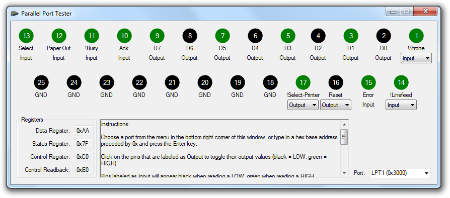
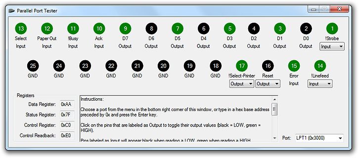
Software-Interface eines Parallel Port Testers
Parallel Port Tester 13 Select Input 12 Paper Out Input 11 !Busy Input 10 Ack Input 9 D7 Output 8 D6 Output 7 D5 Output 6 D4 Output 5 D3 Output 4 D2 Output 3 D1 Output 2 D0 Output 1 !Strobe Input 25 GND 24 GND 23
in „Suche Testprogramm für Printerport“ · PC Hard- und Software · · Screenshots
-
Datei
ulog.c
MYUBRR FOSC/16/BAUD-1 #define ADC_VCC 0 #define ADC_INT 0x80 // 1.1V #define ADC_EXT 0x40 // AIN0 Pin. // PIN DEF #define SCK A,3 #define SI B,1 #define SO A,7 #define CS B,2 #define RX A,5 #define TX A,6 #define STAT B,0 #define RS232_INV 0 // 0 or 1 #define SPI_INP 1 // read on high or low level #
in „Tipps analoger Datenlogger“ · Mikrocontroller und Digitale Elektronik ·
-
Datei
Display_DMC20247.c
) /* Port A Pins PA0 - Quarzeingang (PIN 5) PA1 - Quarzeingang (PIN 4) PA2 - RESET-Programmierleitung (PIN 1)*/ /* Port B Pins PB0 - ??? (Ausgang) (PIN 12) PB1 - ??? (Ausgang) (PIN 13) PB2 - ??? (Ausgang) (PIN
in „Ansteuerung Display DMC2047 mit ATtiny 2313“ · Mikrocontroller und Digitale Elektronik ·
-
Datei
Display_DMC20247.c
) /* Port A Pins PA0 - Quarzeingang (PIN 5) PA1 - Quarzeingang (PIN 4) PA2 - RESET-Programmierleitung (PIN 1)*/ /* Port B Pins PB0 - ??? (Ausgang) (PIN 12) PB1 - ??? (Ausgang) (PIN 13) PB2 - ??? (Ausgang) (PIN
in „Pollin Display DMC 2047“ · Mikrocontroller und Digitale Elektronik ·
-
Datei
httpd.c
[index].new_page_pointer+5)-48); b = 0; switch(pgm_read_byte(http_entry[index].new_page_pointer+4)) { case 'A': b = (PORTA & (1<<pin)); break; case 'B': b = (PORTB & (1<<pin)); break; case 'C': b = (PORTC & (1<<pin)); break; case
in „SD/MMC Webserver“ · Mikrocontroller und Digitale Elektronik ·
-
Datei
main.c
= 300; val++; /* Tasterwert um 1 erhöhen */ } switch(nSelect) { case 0: /* Haupt-Menü */ if (val > 2) val = 0; break; case 1: /* Floppy-ID Menü */ if (val > 6) val = 3; break; case 2: /* Schreibschutz-Menü */ if (val > 9) val = 7; break; } switch(val) { /* Hauptmenü */ case 0: LEDS_PORT = _I; /* I -> ID */ if(get_key_long(MENU_TASTER)) { val = 3; nSelect = 1; } break; case 1: LEDS_PORT = _S; /* S -> Schreibschutz */ if(get_key_long(MENU_TASTER)) { val = 7; nSelect = 2; } break; case 2: LEDS_PORT = _R; /* R -> Reset */ if(get_key_long(MENU_TASTER
in „Zwei Interrupts/Auswertungen gleichzeitig“ · Mikrocontroller und Digitale Elektronik ·
-
Datei
ATB_Menue_1.c
/* ATB_Menue_1.c Created: 13.03.2016 11:35:08 Author : AS */ // ori Teile P30 und P64 und D2 + NT // P64 Tastenboard Belegung Buchsenleiste // Pin 1-frei Pin 2-Servo Pin 3-LED // Pin 4-T1 Pin 5-T2 Pin 6-T3 // Pin 7-T4 Pin 8-T5 // P30 Board 1 Prozessor Port A-Buchsenleiste // PA 0-Pin 1-frei PA 1-Pin 2-Servo // PA 2-Pin 3-LED PA 3-Pin 4-T1 // PA 4-Pin 5-T2 PA 5-Pin 6-T3 // PA 6-Pin 7-T4 PA 7-Pin 8-T5 // T1-hoch, T3-enter
in „Einfaches Menue mit I2C Bus in C“ · Mikrocontroller und Digitale Elektronik ·
-
Datei
Testtool.bas_nach_C.txt
2 von Port D ein high level anliegt, dann... Toggle Portd.5 '...setze Pin 5 von Port D von high auf low oder umgekehrt Bitwait Pind.2 , Reset 'warte bis an Pin 2 von Port D wieder ein low level anliegt End If 'Ende der Bedingung If Pind.3 = 1 Then 'Wenn an Pin 3 von Port D ein high level anliegt, dann... Toggle Portd.6 '...setze Pin 6 von Port D von high auf low oder umgekehrt Bitwait Pind.3 , Reset 'warte bis an Pin 3 von Port D wieder
in „GCC versus BASCOM - Pegelunterschiede“ · Mikrocontroller und Digitale Elektronik ·
-
Datei
LCD.c
#include <avr/io.h> #include <util/delay.h> #include <stdlib.h> #include "LCD.h" #include "LCD_Characters.h" //////////////////////////////////////////////////////////////////////////////// // Erzeugt einen Enable-Puls static void lcd_enable( void ) { LCD_PORT |= (1<<LCD_EN); // Enable auf 1 setzen _delay_us( LCD_ENABLE_US ); // kurze Pause LCD_PORT &= ~(1<<LCD_EN); // Enable auf 0 setzen } //////////////////////////////////////////////////////////////////////////////// // Sendet eine 4-bit Ausgabeoperation an das LCD static void lcd_out( uint8_t data ) { data &= 0xF0; // obere 4 Bit maskieren
in „LCD Sourcefile testen und dann hochladen“ · Mikrocontroller und Digitale Elektronik ·
-
PDF
T83C5121.PDF
function of Port 1 2. Alternate function of Port 3 3. Only for the Code RAM version 4. Only for PLCC52 2 A/T8xC5121 4164G–SCR–07/06 A/T8xC5121 Pin Description Figure 2. 24-pin SSOP Pinout CVSS 1 24 VCC LI 2 23 EVCC
in „[V] 1 Stange ältere (ca. 56St) Atmel AT89C5121 mit Interface für Chipkarten/ SIM (9€)“ · Markt ·
-
PDF
T83C5121.PDF
function of Port 1 2. Alternate function of Port 3 3. Only for the Code RAM version 4. Only for PLCC52 2 A/T8xC5121 4164G–SCR–07/06 A/T8xC5121 Pin Description Figure 2. 24-pin SSOP Pinout CVSS 1 24 VCC LI 2 23 EVCC
in „[V] noch 1 Stange ältere (60St) Atmel AT89C5121 mit Interface für Chipkarten/ SIM (9€)“ · Markt ·
-
PDF
LTC4054-4.2.pdf
3.5 VCC= 4.2V –100 2.5 3.3 –150 A A 2.0 A ( ( ( O 3.1 O O–200 P VCC = 6.5V P1.5 P I I I–250 2.9 1.0 –300 2.7 0.5 VCC = 5V V CC= 5V VBAT = 4.3V –350 V BAT= 4.3V TA = 25°C TA = 25°C 2.5 0 –400 –50 –25 0
in „akku mit solar aufladen, kommt das IC: LT1734L dafür in Frage?“ · Analoge Elektronik und Schaltungstechnik ·
-
Datei
Anzeige.c
#define segd PC3 #define sege PC4 #define segf PC5 #define segg PD0 //Masse Pins #define seg1 PB4 // 1er #define seg2 PB3 // 10er #define seg3 PB2 // 100er #define seg4 PB1 // 1000er volatile unsigned char NrOverflows
in „Drehzahl über ICP“ · Mikrocontroller und Digitale Elektronik ·
-
Datei
humidity.c
|= (1<<RH_SENSOR_SCK); _delay_us(5); if(bit_is_set(RH_SENSOR_PIN,RH_SENSOR_DATA)==0){ bit = 0; } else { bit = 1; } _delay_us(5); RH_SENSOR_PORT = (0<<RH_SENSOR_SCK); _delay_us(5); // PORTB=(bit<<1); // hier wird das gerade eingelesene
in „Feuchtigkeitssensor FOST02A gibt nur 1en aus“ · Mikrocontroller und Digitale Elektronik ·
-
PDF
DAT-31R5A-PP_.pdf
www.minicircuits.com P.O. Box 350166, Brooklyn, NY 11235-0003 (718) 934-4500 sales@minicircuits.com Page 3 of 8 0 6 7 8 9 1 D C C D D D N N/ D N V V G Digital Step Attenuator DAT-31R5A-PP+ Parallel Pin Description Pin Configuration (Top View) Pin 5 D Function Description 0 1 N 2 4 Number C C G C C C16 1 Control for Attenuation bit, 16dB (Note 3, 7) 2 1 1 1 1 RF in 2 RF in port (Note 1) C16 1 15 C8 2 N/C 3 Not connected (Note 4) RFin 2x2mm 14 RFout GND 4 Ground connection N/C 3 Paddle 13 GND LE 5 Latch Enable Input (Note 2) GND 4 ground 12 GND
-
Datei
STBR005.c
Taktfrequenz vom 16Mhz (bei einem anderen Takt müssen die Timer geändert werden.) Taster 1 = PE0 Taster 2 = PE1 Taster 3 = PE2 Taster 4 = PB0 Taster 5 = PB1 Impulse 2 D0 PA4 (Output) Pin 2 Step X Impulse 3 D1 PA5 (Output) Pin 3 Dir X Impulse 4 D2 PA6 (Output) Pin 4 Step Y Impulse 5 D3 PA7 (Output) Pin 5
in „Schrittmotorsteuerung mit Atmega8?“ · Mikrocontroller und Digitale Elektronik ·
-
Datei
STBR005.c
Taktfrequenz vom 16Mhz (bei einem anderen Takt müssen die Timer geändert werden.) Taster 1 = PE0 Taster 2 = PE1 Taster 3 = PE2 Taster 4 = PB0 Taster 5 = PB1 Impulse 2 D0 PA4 (Output) Pin 2 Step X Impulse 3 D1 PA5 (Output) Pin 3 Dir X Impulse 4 D2 PA6 (Output) Pin 4 Step Y Impulse 5 D3 PA7 (Output) Pin 5
in „Schrittmotoren Programmverlauf abfahren lassen“ · Mikrocontroller und Digitale Elektronik ·
-
Datei
STBR005.c
Taktfrequenz vom 16Mhz (bei einem anderen Takt müssen die Timer geändert werden.) Taster 1 = PE0 Taster 2 = PE1 Taster 3 = PE2 Taster 4 = PB0 Taster 5 = PB1 Impulse 2 D0 PA4 (Output) Pin 2 Step X Impulse 3 D1 PA5 (Output) Pin 3 Dir X Impulse 4 D2 PA6 (Output) Pin 4 Step Y Impulse 5 D3 PA7 (Output) Pin 5
in „Schrittmotor, Softstart und Timer?“ · Mikrocontroller und Digitale Elektronik ·
-
PDF
P89C51RC_IN.pdf
R 18 28 P PSEN ALE/PROG Pin Function Pin Function Pin Function N 1 NIC* 16 P3.4/T0 31 P2.7/A15 I RxD 2 P1.0/T2 17 P3.5/T1 32 PSEN T TxD 3 P1.1/T2EX 18 P3.6/WR 33 ALE N U INT0 3 2 4 P1.2/ECI 19 P3.7/RD 34 NIC* F INT1 T R 5 P1.3
in „[V] 8St. 8051er Philips P89C51RC+IA PLCC44 (6€)“ · Markt ·
-
Datei
Tastermatrix.c
/************************************************************************/ /* */ /* Keyboard Interface 3 * 8 */ /* */ /* Author: Peter Dannegger */ /* danni@specs.de */ /* */ /************************************************************************/ /* keyboard Interface: * 3 rows x 8 columns: P0.0 - P0.2 * P2 * support multiple keys pressed simultaniously * if more than two keys pressed, then every key need a decoupling diode * * 0x00 = no key changed * 0x01 .. 0x18 = key released * 0x81 .. 0x98 = key pressed */ #include <avr/io.h> #include <avr/interrupt.h> #include <util/delay.h> #define KEY_PRESS_MASK
in „Taster-Matrix Code von Peda auf AVR“ · Mikrocontroller und Digitale Elektronik ·
-
PDF
GD32E230xx_Datasheet_Rev1.5.pdf
TSSOP20 pin definitions Pin I/O Pin Name Pins (1) (2) Functions description Type Level Default: PF0 PF0-OSCIN 2 I/O 5VT Alternate: I2C0_SDA Additional: OSCIN Default: PF1 PF1- 3 I/O 5VT Alternate: I2C0_SCL OSCOUT
in „Wechselrichter Hoymiles HM-xxxx 2,4 GhZ Nordic Protokoll?“ · Mikrocontroller und Digitale Elektronik ·
-
PDF
STM32breakout_v2.pdf
................ 4 3. Hardwareschnittstellen ........................................... 5 3.1 SPI-Schnittstellen ................................................ 5 2 3.2 I C-Schnittstellen ..............................
in „[V]erkaufe - STM32 F1, F2, F4 Breakoutboard V2“ · Markt ·
-
PDF
STM32breakout_v2.pdf
................ 4 3. Hardwareschnittstellen ........................................... 5 3.1 SPI-Schnittstellen ................................................ 5 2 3.2 I C-Schnittstellen ..............................
in „[V]erkaufe - STM32 F1, F2, F4 Breakoutboard V2“ · Markt ·
-
PDF
SAK-C167CR-LM_HA.pdf
3 V3.2, 2001-07 C167CR C167SR Pin Configuration (top view) I I OIO I 2 2 2 2 C C C C / / C/C / 5 4 3 2 1 0 T 1 1 1 1 1 1 9 8 7 6 5 4 3 2 1 0 D D D D D D D U 1 2 / / A/A / / A/A/ / / / A/A / / A/A / / /
in „Problem mit Infinion C167CR mit AM29F200B-70SE“ · Mikrocontroller und Digitale Elektronik ·
-
PDF
w78c31B.pdf
, P3.3 13 28 P2.7, A15 14 T0, P3.4 27 P2.6, A14 T1, P3.5 15 26 P2.5, A13 WR, P3.6 16 25 P2.4, A12 RD, P3.7 17 24 P2.3, A11 XTAL2 18 23 P2.2, A10 XTAL1 19 22 P2.1, A9 VSS 20 21 P2.0, A8 44-Pin PLCC (W78C31BP
in „Formel für Kondensatoren für Quartz“ · Mikrocontroller und Digitale Elektronik ·
-
Datei
adc0.3_working.c
(int pin) { uint16_t result; //uint8_t result[2]; answer[0]=CMD_ADC_GET; answer[1]=adc_get(pin,&result); //result[0] = 0x77; //result[1] = 0x88; //answer[2]=(char)result[1]; //high //answer[3]=(char)result[0]; //low answer[2]=(char)(result>>8); //high answer[3]=(char)(result); //low CommandAnswer(4); } int adc_get(int pin, uint16_t *value) { *value = 0; if (octopus.ports[pin] == PIN_AD) { switch (pin) { case 40: *value =
in „Merkwürdiges Verhalten meines ADC“ · Mikrocontroller und Digitale Elektronik ·
-
PDF
M16C62_Hardware.pdf
to 85 °C –20 °C to 85 °C –40 °C to 85 °C (5) Which operating supply voltage do you use? 2.7V to 3.2V 3.2V to 3.7V 3.7V to 4.2V 4.2V to 4.7V 4.7V to 5.2V 5.2V to 5.5V Thank you cooperation. 4. Special item (Indicate
in „M16C Parallel pinbelegung“ · Mikrocontroller und Digitale Elektronik ·
-
Datei
main.c
// CH2, CH1, 1V, K1, K2, K3, K4, REF // PORTCFG.MPCMASK = 0b00011110; // // Pull up on pin PA4, PA3, PA2, PA1 PORTA.PIN7CTRL = 0x07; // Input Disable on pin PA7 PORTA.PIN6CTRL = 0x07; // Input Disable on pin PA6 PORTA.PIN5CTRL = 0x07; // Input Disable on pin PA5 PORTA.PIN4CTRL = 0x18; // Pull up on pin PA4 PORTA.PIN3CTRL = 0x18; // Pull up on pin PA3 PORTA.PIN2CTRL = 0x18; // Pull up on pin PA2 PORTA.PIN1CTRL = 0x18;
in „ATXmega - Pin Eingang oder Ausgang“ · Mikrocontroller und Digitale Elektronik ·
-
PDF
techb_mysmartusb-mk2_de_en.pdf
www.myAVR.de © Laser & Co. Solutions GmbH - 05/2009 www.myAVR.com Technische Beschreibung mySmartUSB MK2, Version 2.11 Seite: 5/16 Schnittstellendaten Interface Data Standard-ISP 10 polig, Wannenstecker Standard-ISP 10 pin, print plug Pin ISP Pin ISP 1 MOSI 1 MOSI 2 VCC 2 VCC 3 GND 3 GND 4 GND 4 GND 5 RESET 5 RESET 6 GND 6 GND 7 SCK 7 SCK 8 GND 8 GND 9 MISO 9 MISO 10 GND 10 GND GND AVR ISP 10 9 8 7 MISO SCK 6 5 4 3 RST 2 1 GND VCC MOSI mySmartUSB MK2 Interface mySmartUSB MK2 interface Pin Pin 1 nicht benutzen
in „Mikro brauch nach übertragen meistens noch einen Reset“ · Mikrocontroller und Digitale Elektronik ·
-
Datei
main.c
include <avr/io.h> #include <util/delay.h> #include "defines.h" #include "uart/uart.h" #define SETPIN(port, pins) port |= pins #define UNSETPIN(port, pins) port &= ~pins typedef enum { RELAIS_1, RELAIS_2, RELAIS_3, RELAIS_4, RELAIS_5, NOF_RELAIS } Relais_te; typedef struct { const uint8_t pin; bool state_b; } Relais_ts; static Relais_ts relais_as[NOF_RELAIS] = { [RELAIS_1] = { .pin = (1 << PINB1), .state_b = false }, [RELAIS_2] = { .pin = (1 << PINB2), .state_b = false }, [RELAIS_3] = { .pin = (1 << PINB3), .state_b = false }, [RELAIS_4] = { .pin = (1 << PINB4), .state_b = false
in „Strukt initialisieren probleme“ · Mikrocontroller und Digitale Elektronik ·
-
Datei
i2c_mp3_slave.asm
1) .equ I2C_PORT = PORTB .equ SCL = PB7 ;mit externem Pull-up 10k .equ SDA = PB5 ;mit externem Pull-up 10k .equ START = 's' .equ ACK = 'a' .equ NACK = 'n' .equ STOP = 'p' .equ I2C_DDR = I2C_PORT - 1 .equ I2C_PIN
in „MP3 Player an CD Wechsler Anschluss“ · Mikrocontroller und Digitale Elektronik ·
-
Datei
lowlevel_ov7670.h
SC OV7670 //2.0 ... 2.7 ?? 1.24 1.23 1.20 ++ -- rst 0.5 2.12 0.11 0.00 0.01 //a0 a1 a2 a3 a4 a5 a6 a7 c4 c5 c6 c7 + - d5 d6 d7 c2 c3 M1284 #define DatenPORT 2 #define Value_Datenbus FIO2PIN0 #define SCCB_C_PORT 0
in „DMA-Datentransfer OV7670 -> ARM-MCU“ · Mikrocontroller und Digitale Elektronik ·
-
Datei
SSD1963.c
GPIO_InitStructure.GPIO_Speed = GPIO_Speed_50MHz; // Speed 50 MHz GPIO_Init (GPIOB, &GPIO_InitStructure); // Init Port B // PORT D INIT ------------------------------------------------------------------------------------- GPIO_PinAFConfig (GPIOD, GPIO_PinSource0, GPIO_AF_FSMC); // PD0=FSMC_D2 -> DB2 GPIO_PinAFConfig (GPIOD, GPIO_PinSource1, GPIO_AF_FSMC); // PD1=FSMC_D3 -> DB3 GPIO_PinAFConfig (GPIOD, GPIO_PinSource4, GPIO_AF_FSMC); // PD4=FSMC_NOE -> RD GPIO_PinAFConfig (GPIOD, GPIO_PinSource5, GPIO_AF_FSMC); // PD5=FSMC_NWE -
in „7 Zoll LCD Display“ · Mikrocontroller und Digitale Elektronik ·
-
Datei
licht.c
port=2; unsigned int ports=5; unsigned int programm=1; unsigned int dimm_all=1; inline uint8_t debounce(volatile uint8_t *port, uint8_t pin) { if ( ! (*port & (1 << pin)) ) { /* Pin wurde auf Masse gezogen
in „Komisches Flackern bei Dimmer - Wer kann helfen?“ · Mikrocontroller und Digitale Elektronik ·
-
Datei
main.c
while the slower digits calculation is only done once per change. */ #include "Arduino.h" // esp32c3, ACM-native usb, usb_cdc enabled uint8_t seg[10]={0x3F,0x06,0x5B,0x4F,0x66,0x6D,0x7D,0x07,0x7F,0x6F}; // 7 segment font uint8_t clo[25]={0,1,0,2,0,3,4,1,2,3,3,4,4,4,2,1,3,4,0,1,2,3,2,1,0}; // charlieplex lowpin uint8_t chi[25]={1,0,2,0,3,0,0,2,1,2,1,1,2,3,3,3,5,5,5,5,5,4,4,4,4}; // .. and highpin hw_timer_t *t=NULL;int32_t b,port; // buffers nstuff uint8_t i,s,pin[6]={4,5,6,7,20,21}; // *** CHANGE THIS *** // display io pins void
in „fumot 12.000-Puffs Einweg-Vape mit LED-Display“ · Offtopic ·
-
Datei
config_328.h
LCD_DB5 PD1 /* port pin used for DB5 */ #define LCD_DB6 PD2 /* port pin used for DB6 */ #define LCD_DB7 PD3 /* port pin used for DB7 */ #define LCD_RS PD4 /* port pin used for RS */ #define LCD_EN1 PD5 /* port
-
Datei
UART_STM32F10x.c
/* ---------------------------------------------------------------------- * Copyright (C) 2013 ARM Limited. All rights reserved. * * $Date: 12. September 2013 * $Revision: V1.01 * * Driver: Driver_UART1, Driver_UART2, Driver_UART3, * Driver_UART4, Driver_UART5 * Configured: via RTE_Device.h
in „Einbindung einer .c ohne .h“ · Mikrocontroller und Digitale Elektronik ·
-
Datei
main.c
#include <avr/io.h> #include <stdlib.h> #include <string.h> #include <avr/interrupt.h> #include <avr/pgmspace.h> #include <avr/eeprom.h> #define globals_main #include "main.h" #include <util/delay.h> //================================================ // pb0 pb1 pb2 pb3 pb4 pb5 // tx led t1 t2 - rst #define dali_port B #define dali_pin 0 void dali_tx_init(void){ PORT(dali_port) |= (1<<dali_pin); (DDR(dali_port) &= ~(1<<dali_pin)); } uint8_t dali_tx_byte(u8 dat){ uint8_t i; for(i=0;i<8;i++){ if(dat & 0x80){ PORT(dali_port) &= ~(1<<dali_pin); _delay_us(416); PORT(dali_port) |= (1<<dali_pin); _delay_us
-
PDF
DAT-31R5A-PN_.pdf
(Note 3,6) C C G C C 2 1 1 1 1 RF in 2 RF in port (Note 1) C16 1 15 C8 N/C 3 Not connected (Note 4) GND 4 Ground connection RFin 2 2x2mm 14 RFout N/C 3 Paddle 13 GND LE 5 Latch Enable Input (Note 2) GND 4 ground
-
Datei
config_328.h
LCD_DB5 PD1 /* port pin used for DB5 */ #define LCD_DB6 PD2 /* port pin used for DB6 */ #define LCD_DB7 PD3 /* port pin used for DB7 */ #define LCD_RS PD4 /* port pin used for RS */ #define LCD_EN1 PD5 /* port
in „ComponentTester-1.42m problem“ · Mikrocontroller und Digitale Elektronik ·