-
Datei
rfm12.c
---------*/ volatile unsigned char delaycnt=0; volatile unsigned char secflag; unsigned char rxbuf[MAX_BUF+1]; // Puffer für empfangene Daten unsigned char txbuf[MAX_BUF+1]; // Puffer für zu sendende Daten unsigned char flags, tx_cnt, rx_cnt, tx_id, tx_status, retrans_cnt; struct TELEGRAM Telegram; unsigned
in „RFM12 und STM32F1xx“ · Mikrocontroller und Digitale Elektronik ·
-
PDF
CS42L51_F3.pdf
be selected using the SPEED[1:0] bits. Auto-Detect QSM HSM SSM DSM Disabled 512, 768, 1024, 1536, 256, 384, 512, 768, 128, 192, 256, 384, (Software 2048, 3072 1024, 1536 512, 768 128, 192, 256, 384 Mode only) 1024, 1536, 2048*, Enabled 512, 768, 1024*, 1536* 256, 384, 512*, 768* 128, 192, 256*, 384*
in „STM32H7B3I-DK - Soundausgabe“ · Mikrocontroller und Digitale Elektronik ·
-
PDF
PCA9531_5-181573.pdf
Blink period = 1 = ----------------------- 152 PSC0 = 151 Set PWM0 duty cycle to 50 %: 80h -WM0 = 0.5 256 PWM0 = 128 Set prescaler PCS1 to dim at maximum frequency: 00h Blink period = max PSC1 = 0 Set PWM1 output duty cycle to 25 %: 40h -WM1 = 0.25 256 PWM1 = 64 Set LED0 to LED3 on 55h Set LED4 and LED5
in „[V] 3St. SMD 8-bit I2C LED Treiber NXP PCA9531D (SO16)“ · Markt ·
-
Datei
Reislampe3.cc
F_PWM 100L // PWM-Frequenz in Hz #define PWM_PRESCALER 8 // Vorteiler für den Timer #define PWM_STEPS 256 // PWM-Schritte pro Zyklus(1..256) #define PWM_PORT PORTB // Port für PWM #define PWM_DDR DDRB // Datenrichtungsregister für PWM #define PWM_CHANNELS 8 // Anzahl der PWM-Kanäle // ab hier nichts ändern
in „error: invalid types 'bool[int]' for array subscript“ · Mikrocontroller und Digitale Elektronik ·
-
Datei
rf12.c
rf12_rxbyte(); // Anzahl der zu empfangenden Bytes crc=_crc_ccitt_update (crc, number); if (number>MAX_BUF) number=MAX_BUF; if (number) { *id=rf12_rxbyte(); // Paketnummer crc=_crc_ccitt_update (crc, *id); for (i=0; i<number; i++) { *data=rf12_rxbyte(); crc=_crc_ccitt_update (crc, *data); data++; } } crcref=rf12_rxbyte(); // CRC empfangen crcref|=rf12_rxbyte()*256; // CRC empfangen rf12_trans(0xCA81); // restart syncword detection: #ifdef USE_868 rf12_trans(0xCAF3); // enable FIFO: sync word search #else rf12_trans(0xCA83); // enable FIFO: sync word search #endif
in „Bausatz Add-on für AVR-NET-IO“ · Mikrocontroller und Digitale Elektronik ·
-
Datei
main.c
F_PWM 100L // PWM-Frequenz in Hz #define PWM_PRESCALER 8 // Vorteiler für den Timer #define PWM_STEPS 256 // PWM-Schritte pro Zyklus(1..256) #define PWM_PORT PORTD // Port für PWM #define PWM_DDR DDRD // Datenrichtungsregister für PWM #define PWM_CHANNELS 8 // Anzahl der PWM-Kanäle // ab hier nichts ändern
in „Soft-PWM Version 3: Probleme beim Anpassen des Programms“ · Mikrocontroller und Digitale Elektronik ·
-
Datei
main.c
F_PWM 100L // PWM-Frequenz in Hz #define PWM_PRESCALER 8 // Vorteiler für den Timer #define PWM_STEPS 256 // PWM-Schritte pro Zyklus(1..256) #define PWM_PORT PORTD // Port für PWM #define PWM_DDR DDRD // Datenrichtungsregister für PWM #define PWM_CHANNELS 8 // Anzahl der PWM-Kanäle // ab hier nichts ändern
in „Soft-PWM Version 3: Probleme beim Anpassen des Programms“ · Mikrocontroller und Digitale Elektronik ·
-
Datei
treppenlicht.c
F_PWM 100L // PWM-Frequenz in Hz #define PWM_PRESCALER 8 // Vorteiler für den Timer #define PWM_STEPS 256 // PWM-Schritte pro Zyklus(1..256) #define PWM_PORT_1 PORTD // Port für PWM #define PWM_DDR_1 DDRD // Datenrichtungsregister für PWM #define PWM_PORT_2 PORTC // Port für PWM #define PWM_DDR_2 DDRC /
in „Einschaltverzögerung Bodenstrahler mit BM“ · Haus & Smart Home ·
-
Datei
main.c
ioC8051F320.h" #include "USB_API.h" #define USBXpress_int 0x83 BYTE pac[64]; __xdata BYTE SPIbuffer[256]; void SPI_Init(void); __code const unsigned int USB_VID = 0x10C4; __code const unsigned int USB_PID = 0xEA61; __code const char USB_MaxPower = 15; // maximaler Strom 2x15 mA __code const unsigned int
in „Puffer-Problem mit C8051F320 (8051)“ · Mikrocontroller und Digitale Elektronik ·
-
PDF
MX25L6405D__3V__64Mb__v1.5.pdf
: 50MHz (15pF + TTL Load), which is equivalent to 100MHz - Fast program time: 1.4ms(typ.) and 5ms(max.)/page (256-byte per page) - Byte program time: 9us (typical) - Continuously program mode (automatically increase address under word program mode) - Fast erase time: 60ms(typ.) /sector (4K-byte per
in „FLASH Memory Chip im Lenovo X200 von 8 MB auf 16 MB vergroessern“ · PC Hard- und Software ·
-
PDF
sle4432_0795.pdf
G1-X-7600 Siemens Aktiengesellschaft Printed in Germany DA 07952. Semiconductor Group 4 Intelligent 256-Byte EEPROM with Write Protect Function SLE 4432 Intelligent 256-Byte EEPROM with Write Protect Function SLE 4442 and P rogrammable Security Code (PSC) Features ● 256 × 8-bit EEPROM organization ● Byte-wise
-
PDF
SLE4432__SLE4442.pdf
G1-X-7600 Siemens Aktiengesellschaft Printed in Germany DA 07952. Semiconductor Group 4 Intelligent 256-Byte EEPROM with Write Protect Function SLE 4432 Intelligent 256-Byte EEPROM with Write Protect Function SLE 4442 and P rogrammable Security Code (PSC) Features ● 256 × 8-bit EEPROM organization ● Byte-wise
in „smartcard sle4442“ · Mikrocontroller und Digitale Elektronik ·
-
PDF
bq2060a.pdf
Relative StateOfCharge() is more likely between 50% and 60%. The bq2060A sets MaxError() to 100% on a full reset. The bq2060A sets MaxError() to 2% on completion of a learning cycle, unless the bq2060A limits the learning cycle to the +512/–256-mAh maximum adjustment values. If the learning cycle is limited, the bq2060A sets MaxError() to 8% unless MaxError() was already below 8%. In this case MaxError() does not change. The bq2060A increments MaxError() by 1% after four increments of CycleCount() without a learning cycle.
in „Verstehe dieses Datenblatt nicht (BQ2060A)“ · Mikrocontroller und Digitale Elektronik ·
-
Datei
mix.asm
_t v1,uint8_t v2, uint8_t f ); */ /* How does it work? General interpolation: res = V1 + (V2-V1)*f/max <=> res = (V2*f + V1*(max-f))/max <=> res = (V2*f + V1*(max-1-f) + V1)/max if max is a 2^n value then <=> res = (V2*f + V1*(~f) + V1)/max because ~f+1 = -f = max-f Example: for 4 bits (-> max is 16)
in „Lineare Interpolation in 30 Bytes auf attiny“ · Mikrocontroller und Digitale Elektronik ·
-
PDF
ISL88731.PDF
, F is the Acknowledge. The master then sends the higher data byte to be IN,MAX SW written into the desired register. The ISL88731 will respond with switching frequency and I L,MAX is the max DC current in the an Acknowledge. The master then issues a Stop condition, inductor. indicating to the ISL88731 that the current transaction is For VIN,MAX = 20V, VBAT = 12.6V, IBAT,MAX = 4.5A, and complete. Once this transaction completes the ISL88731 will fs= 400kHz, the calculated inductance is 9.3µH. Choosing the begin operating at the new current
in „Chip gesucht“ · Mikrocontroller und Digitale Elektronik ·
-
PDF
TMC262_datasheet.pdf
// Hysteresis mode or SPI = $94557; // Constant offmode SPI = $D001F; // Current setting: $d001F (max. current) SPI = $EF010; // high gate driver strength, stallGuard read, SDOFF=0 SPI = $00000; // 256 microstep setting First test of coolStep current control: SPI = $A8202; // Enable coolStep with minimum
in „Wärmeentwicklung Mosfet“ · Mikrocontroller und Digitale Elektronik ·
-
PDF
ET6622.pdf
a peripheral device specially designed for I/O type MCU used to expand the display capability. The max. Display segment of the device are 256 patterns (32×8). The ET6622 is a memory mapping and multi-function LCD controller. Features ⚫ Operating voltage: 2.7V~5.2V ⚫ Built-in 32 kHz RC oscillator ⚫ 1/4bias, 1/8duty, frame frequency is 64Hz ⚫ Max.32×8 patterns, 8 commons, 32 segments ⚫ Built-in internal resistor type bias generator ⚫ 3-wire serial interface ⚫ 8 kinds of time base/WDT selection ⚫ Time base or WDT over flow output ⚫ Built-in LCD
in „Hilfe bei Fehlersuche auf Platine (Displayanzeige schwach)“ · Mikrocontroller und Digitale Elektronik ·
-
Datei
main.c
] = '\0'; for (max_chars--; max_chars > sign && num!=0; max_chars --) { remainder = (int8_t) (num % base); if ( remainder <= 9 ) string[max_chars] = remainder + '0'; else string[max_chars] = remainder - 10 + 'A'; num /= base; } if (sign) string[--max_chars] = '-'; if ( max_chars > 0 ) memset(string, ' ', max_chars+1); return string + max_chars; } #endif
in „Atmega2560+SSD1963 SD-Karte“ · Mikrocontroller und Digitale Elektronik ·
-
Datei
Wellengruppen_1_.bas
11101110_11101110_11101110 Pulsfolge_array(5) = &B11111111_11111111_11111111_11111111 Pulsfolge = 0 ' Max Halbwellen je Gruppe Halbwellen_max = 20 ' Halbwellen_max muss gerade sein! Halbwellen_max.0 = 0 Do #if Dim_art = 0 ' Gruppen_MAX Ende; Neuer Zyklus! Feuerfreigabe einschalten If Halbwelle_count >= Halbwellen_max Then Halbwelle_count = 0 Set Fire_access ' Eingestellte max. Wellenanzahl erreicht, Freigabe abschalten Elseif Halbwelle_count = Stellwert Then Reset Fire_access End If #endif #if Dim_art = 1 'Vollwellen
in „Leistungsreduzierung eines Kondensatormotors einer Poolpumpe (600W)“ · Haus & Smart Home ·
-
PDF
Western_Digital_FD1791.pdf
zero, then the sector length is 128 bytIf. vided for write precompensation. These are EARLY 01 then 256 bytes. If 02, then 512 bytes. If 03, then the (Pin 17) and LATE (Pin 18). EARLY is active true sector length is 1024 bytes. The number of sectors when the WD pulse appearing on (Pin 30) is to be per
in „(S)uche FDC SAB 1791 02P“ · Markt ·
-
PDF
howto_-tasmota-sml.pdf
Um Energiezähler mit Modbus Schnittstelle auslesen zu können, ist ein Modbus2TTL Adapter nötig. - MAX485 RS485 zu TTL Adapter o. Ä. - Kompatibler Modbus Zwischenzähler 1P/3P - Modbusregisterübersicht! 4 Wasseruhr Hierzu gibt es verschiedene Optionen. Leider gibt es eine vielzahl verschiedener Wasseruhren
in „Wärmezähler über optische M-Bus-Schnittstelle auslesen“ · Haus & Smart Home ·
-
Datei
Main.c
include <avr/io.h> #include <avr/interrupt.h> #include <util/delay.h> int transition = 0; int divisorMax = 256; ISR( TIMER0_OVF_vect ) //Overflow { static uint8_t divisor = 0; divisor++; if( divisor >= 0 && divisor < transition ) { for(int i = 0; i < 16; i++) { SPDR = 0b00000000; // Schreibe Daten... while
in „PWM über 74hc595 (Pulsweitenmodulation über Schieberegister) - in C“ · Mikrocontroller und Digitale Elektronik ·
-
PDF
AS1130_Datasheet_EN_v5__1_.pdf
LED Matrix driving 132 LEDs can be analog dimmed from 0 to 30mA in Individual 8 bit LED PWM Control 256 steps (8 bit). 8 bit Analog Brightness Control 8 bit Dot Correction for optimize RGB LED Operation Additionally each of the 132 LEDs can be dimmed individually with 8 bitallowing 256 steps of linear
-
PDF
SSD1332_R1.61.pdf
selectable 6800/8000 series compatible Parallel Interface or Serial Peripheral Interface. It has a 256 steps contrast control and 65K color control. 2 FEATURES Support max. 96RGB x 64 matrix panel Power supply: V DD= 2.4V - 3.5V VCC= 7.0V - 18.0V OLED driving output voltage, 16V maximum DC-DC voltage
in „OLED und 8051“ · Mikrocontroller und Digitale Elektronik ·
-
PDF
2287522.pdf
LED15). • A lower 122 Hz fixed frequency signal with programmable duty cycle (8 bits, 256 steps) is used to provide a global brightness control. • A programmable frequency signal from 15 Hz to every 16.8 seconds (8 bits, 256 steps) with programmable duty cycle (8 bits, 256 steps) is used
in „[V] 10St. NXP PCA9955 16-channel Fm+ I2C-bus 57 mA/20 V constant current LED driver SSOP28 (10€)“ · Markt ·
-
PDF
2287522.pdf
LED15). • A lower 122 Hz fixed frequency signal with programmable duty cycle (8 bits, 256 steps) is used to provide a global brightness control. • A programmable frequency signal from 15 Hz to every 16.8 seconds (8 bits, 256 steps) with programmable duty cycle (8 bits, 256 steps) is used
in „[V] 10St. NXP PCA9955 16-channel Fm+ I2C-bus 57 mA/20 V constant current LED driver SSOP28“ · Markt ·
-
PDF
SPEC-2400__LV_and_C__L_-_May_2013_.pdf
SOURCE-MEASURE TO GPIB 5 TO GPIB Fast (488.1) 0.01 / internal 537 140 135 Fast (488.2) 0.01 / internal 256 (256) 79 (83) 79 (83) Medium (488.2) 0.10 / internal 167 (166) 72 (70) 69 (70) Normal (488.2) 1.00 / internal 49 (42) 34 (31) 35 (30) 4,6,8 COMPONENT INTERFACE HANDLER TIME FOR 60Hz (50Hz): SOURCE-MEASURE
in „Messunsicherheiten Keithly 2400 Sourcemeter“ · Analoge Elektronik und Schaltungstechnik ·
-
Datei
CAPTURE.TXT
, ways:4, linesz:32 ,total:65536 dcache: sets:256, ways:4, linesz:32 ,total:32768 ##### The CPU freq = 500 MHZ #### estimate memory size =32 Mbytes Please choose the operation: 1: Load system code to SDRAM via TFTP. 2: Load system code then write to
in „Plunder von Pollin:WMDR-143N“ · Mikrocontroller und Digitale Elektronik ·
-
PDF
Maxon_EC16.pdf
Axiallast < 3.5 N 0 mm > 3.5 N max. 0.14 mm 25 Radialspiel vorgespannt Typenleistung 26 Max. axiale Belastung (dynamisch) 3 N 27 Max. axiale Aufpresskraft (statisch) 40 N (statisch, Welle abgestützt) 250 N maxon Baukastensystem Übersicht Seite 17 - 21 28 Max. radiale Belastung, 5 mm ab Flansch 10 N Planetengetriebe Encoder MR Weitere Spezifikationen Æ22 mm 128 / 256 / 512 Imp., 29 Polpaarzahl 1 0.5 - 2.0 Nm 2 / 3 Kanal 30 Anzahl Phasen 3 Seite 221 Seite
in „EC Motor mit dsPIC30 ansteuern“ · Digitale Signalverarbeitung / DSP / Machine Learning ·
-
Datei
IPCONFIG.txt
e-mail demo web page // -- SSL Options -------------------------------------------------------- #define MAX_SSL_CONNECTIONS (2ul) // Maximum connections via SSL #define MAX_SSL_SESSIONS (2ul) // Max # of cached SSL sessions #define MAX_SSL_BUFFERS (4ul) // Max # of SSL buffers (2 per socket) #define MAX_SSL_HASHES
in „TCP/IP Stack Konfiguration des GenericTCPServers“ · Mikrocontroller und Digitale Elektronik ·
-
 Bild
Bild
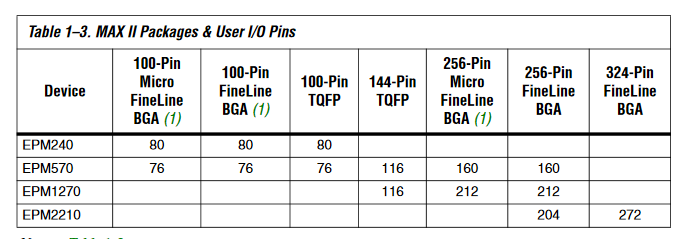
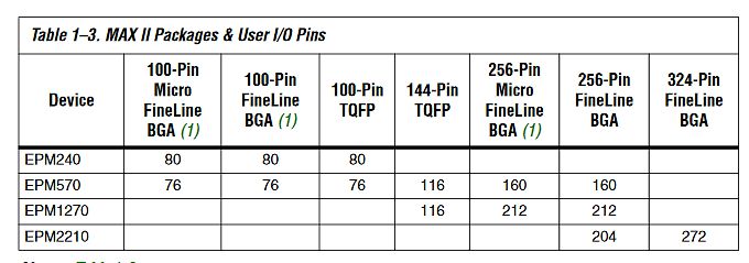
Tabelle der MAX II Pakete und User I/O Pins
Table 1-3. MAX II Packages & User I/O Pins Device 100-Pin Micro FineLine BGA (1) 100-Pin FineLine BGA (1) 100-Pin TQFP 144-Pin TQFP 256-Pin Micro FineLine BGA (1) 256-Pin FineLine BGA 324-Pin FineLine BGA EPM240 80
in „EPM240 zu klein, was jetzt?“ · FPGA, VHDL & Co. · · Screenshots
-
Datei
termstat.asm
ADCC: ;ISR ADC-Wandlung fertig in srsk,sreg ;SREG sichern (Exklusivregister) push xl sub adcn,adcw ;1/256 des ADC-Wertes sbc adcw,null ;mit Übertrag rausnehmen lds xl,adch ;ADC-Wert einlesen add adcn,xl ;1/256 des neuen ADC-Wertes adc adcw,null ;mit Übertrag addieren pop xl out sreg,srsk ;SREG wiederherstellen
in „Pollin LCD1602 keine Anzeige“ · Mikrocontroller und Digitale Elektronik ·
-
Datei
termstat.asm
ADCC: ;ISR ADC-Wandlung fertig in srsk,sreg ;SREG sichern (Exklusivregister) push xl sub adcn,adcw ;1/256 des ADC-Wertes sbc adcw,null ;mit Übertrag rausnehmen lds xl,adch ;ADC-Wert einlesen add adcn,xl ;1/256 des neuen ADC-Wertes adc adcw,null ;mit Übertrag addieren pop xl out sreg,srsk ;SREG wiederherstellen
in „PWM zur Tonausgabe auf einem Lautsprecher Mega8“ · Mikrocontroller und Digitale Elektronik ·
-
PDF
xminilab-manual.pdf
are acquired to fill the buffer, and then they are displayed on the screen. Only 128 samples of the 256 are visible at a single time. - Slow Sampling (20ms/div or slower): Single samples are acquired and simultaneously displayed on the display. All 256 samples are visible on the display (each vertical
in „USART - xmodem (Xminilab) - Bildübertragung“ · Mikrocontroller und Digitale Elektronik ·
-
PDF
xminilab-manual.pdf
are acquired to fill the buffer, and then they are displayed on the screen. Only 128 samples of the 256 are visible at a single time. - Slow Sampling (20ms/div or slower): Single samples are acquired and simultaneously displayed on the display. All 256 samples are visible on the display (each vertical
in „ATXmega32 flashen mit ATMEL Flip (Xminilab)“ · Mikrocontroller und Digitale Elektronik ·
-
PDF
MCP4261-DigitalPot-2Fach-50kDATASHEET.pdf
0 W 60 85°C -0.2 W 60 -40°C -40°C 25°C 125°C 85°C25°C DNL 20 -0.3 20 -2 0 32 64 96 128 160 192 224 256 0 32 64 96 128 160 192 224 256 Wiper Setting (decimal) Wiper Setting (decimal) FIGURE 2-7: 5 k Ω Pot Mode – R W (Ω), FIGURE 2-10: 5 kΩ Rheo Mode – R W (Ω), INL (LSb), DNL (LSb) vs. Wiper Setting and
in „Step Down Regler zu heiss & Fragen zur Umsetzbarkeit einer Schaltung“ · Analoge Elektronik und Schaltungstechnik ·
-
Datei
SerComm.asm
ist um 1 Byte länger ; als der Empfangspuffer, da das erste Byte ; des Strings seine Länge angibt (<256). ;R_exch: .BYTE 1 ; Länge der zu erwartenden Übertragung ;R_cs: .BYTE 1 ; Prüfsumme ; Interrupt-Vektoren setzen ; .CSEG ; was ab hier folgt kommt in den ; ; FlashSpeicher ; .ORG 0x0000 ; Beginn des
in „Abschlussprojekt“ · Mikrocontroller und Digitale Elektronik ·
-
Datei
main01.c
Servo-Signal aus (=>~ 1 - 2 ms) } //Zufallszahlen für Zeitwerte volatile uint8_t laufZeit=0; //Zur Info: Max-Werte für Zeit: 245 (x+10<256), Anzahl: 50 //Ablage erfolgt im Flash-Speicher, um RAM zu sparen //const uint8_t zeitWerteSekundaer[50] PROGMEM = {52, 99, 167, 3, 55, 22, 119, 27, 153, 85, 22, 10, 103
in „AVR ATTiny13A Problem mit Servo + LED-Ansteuerung“ · Mikrocontroller und Digitale Elektronik ·
-
Datei
I2C_128x64_Beispielcode.ino
(); for(int16_t i=max(display.width(),display.height())/2; i>0; i-=3) { // The INVERSE color is used so circles alternate white/black display.fillCircle(display.width() / 2, display.height() / 2, i, SSD1306_INVERSE); display.display
in „I2C 128x64 Display Displayfehler“ · Mikrocontroller und Digitale Elektronik ·
-
PDF
RS232_Zeiss_DSM_Komandos.pdf
M03 zusammengesetzt). Kode M01: gefolgt von 9 Zeichen für die X-Achse Wertebereich 000000.00 bis X max. Kode M02: gefolgt von 9 Zeichen für die Y-Achse Wertebereich 000000.00 bis Y max. Kode M03: gefolgt von 5 Zeichen für die Z-Achse Wertebereich 00000 bis Z max. Kode M05: gefolgt von 5 Zeichen für die
in „Rasterelektronenmikroskop Zeiss DSM 960“ · Digitale Signalverarbeitung / DSP / Machine Learning ·
-
Datei
u-boot.cfg.txt
1 #define CONFIG_DEFAULT_ENV_FILE "uEnv.txt" #define CONFIG_MMC_HS200_SUPPORT 1 #define CONFIG_SYS_MAX_FLASH_SECT 512 #define CONFIG_CLK 1 #define CONFIG_PHYLIB 1 #define CONFIG_CMDLINE_EDITING 1 #define CONFIG_DM_SERIAL 1 #define CONFIG_SYS_CONSOLE_IS_IN_ENV 1 #define CONFIG_ARCH_FIXUP_FDT_MEMORY 1
in „Linux Kernel 5.1.1. auf dem BPi-R2“ · PC Hard- und Software ·
-
PDF
PCA9533.pdf
Blink period = 1 = ----------------------- 152 PSC0 = 151 Set PWM0 duty cycle to 50 %: 80h -WM0 = 0.5 256 PWM0 = 128 Set prescaler PCS1 to dim at maximum frequency: 00h Blink period = max PSC1 = 0 Set PWM1 output duty cycle to 25 %: 40h -WM1 = 0.25 256 PWM1 = 64 Set LED0 on, LED1 off; LED2 set to blink
in „[V] 20St 4-Bit I2C LED PWN Treiber NXP PCA9533 (SO8) (1€/St)“ · Markt ·
-
PDF
PCA9533.pdf
Blink period = 1 = ----------------------- 152 PSC0 = 151 Set PWM0 duty cycle to 50 %: 80h -WM0 = 0.5 256 PWM0 = 128 Set prescaler PCS1 to dim at maximum frequency: 00h Blink period = max PSC1 = 0 Set PWM1 output duty cycle to 25 %: 40h -WM1 = 0.25 256 PWM1 = 64 Set LED0 on, LED1 off; LED2 set to blink
in „[V] einige 4 Bit I2C LED PWN Treiber NXP PCA9533 (SO8)“ · Markt ·
-
PDF
PCA9533.pdf
Blink period = 1 = ----------------------- 152 PSC0 = 151 Set PWM0 duty cycle to 50 %: 80h -WM0 = 0.5 256 PWM0 = 128 Set prescaler PCS1 to dim at maximum frequency: 00h Blink period = max PSC1 = 0 Set PWM1 output duty cycle to 25 %: 40h -WM1 = 0.25 256 PWM1 = 64 Set LED0 on, LED1 off; LED2 set to blink
in „[V] 4-Bit I2C LED PWN Treiber NXP PCA9533 (TSSOP-8) (1€/St)“ · Markt ·
-
PDF
PCA9533.pdf
Blink period = 1 = ----------------------- 152 PSC0 = 151 Set PWM0 duty cycle to 50 %: 80h -WM0 = 0.5 256 PWM0 = 128 Set prescaler PCS1 to dim at maximum frequency: 00h Blink period = max PSC1 = 0 Set PWM1 output duty cycle to 25 %: 40h -WM1 = 0.25 256 PWM1 = 64 Set LED0 on, LED1 off; LED2 set to blink
in „[V] 4-Bit I2C LED PWN Treiber NXP PCA9533 (TSSOP-8) (12€ / 20St)“ · Markt ·
-
PDF
PCA9533.pdf
Blink period = 1 = ----------------------- 152 PSC0 = 151 Set PWM0 duty cycle to 50 %: 80h -WM0 = 0.5 256 PWM0 = 128 Set prescaler PCS1 to dim at maximum frequency: 00h Blink period = max PSC1 = 0 Set PWM1 output duty cycle to 25 %: 40h -WM1 = 0.25 256 PWM1 = 64 Set LED0 on, LED1 off; LED2 set to blink
in „[V] nochmal 4-Bit I2C LED PWN Treiber NXP PCA9533 (TSSOP-8) (12€ / 20St)“ · Markt ·
-
PDF
PCA9533.pdf
Blink period = 1 = ----------------------- 152 PSC0 = 151 Set PWM0 duty cycle to 50 %: 80h -WM0 = 0.5 256 PWM0 = 128 Set prescaler PCS1 to dim at maximum frequency: 00h Blink period = max PSC1 = 0 Set PWM1 output duty cycle to 25 %: 40h -WM1 = 0.25 256 PWM1 = 64 Set LED0 on, LED1 off; LED2 set to blink
in „[V] 4-Bit I2C LED PWN Treiber NXP PCA9533 (TSSOP-8) (12€ / 20St)“ · Markt ·
-
PDF
PCA9533.pdf
Blink period = 1 = ----------------------- 152 PSC0 = 151 Set PWM0 duty cycle to 50 %: 80h -WM0 = 0.5 256 PWM0 = 128 Set prescaler PCS1 to dim at maximum frequency: 00h Blink period = max PSC1 = 0 Set PWM1 output duty cycle to 25 %: 40h -WM1 = 0.25 256 PWM1 = 64 Set LED0 on, LED1 off; LED2 set to blink
in „[V] 4-Bit I2C LED PWN Treiber NXP PCA9533 (TSSOP-8) (30St/17€)“ · Markt ·
-
PDF
PCA9533.pdf
Blink period = 1 = ----------------------- 152 PSC0 = 151 Set PWM0 duty cycle to 50 %: 80h -WM0 = 0.5 256 PWM0 = 128 Set prescaler PCS1 to dim at maximum frequency: 00h Blink period = max PSC1 = 0 Set PWM1 output duty cycle to 25 %: 40h -WM1 = 0.25 256 PWM1 = 64 Set LED0 on, LED1 off; LED2 set to blink
in „[V] 4-Bit I2C LED PWN Treiber NXP PCA9533 (TSSOP-8) (30St/12€)“ · Markt ·
-
PDF
PCA9533.pdf
Blink period = 1 = ----------------------- 152 PSC0 = 151 Set PWM0 duty cycle to 50 %: 80h -WM0 = 0.5 256 PWM0 = 128 Set prescaler PCS1 to dim at maximum frequency: 00h Blink period = max PSC1 = 0 Set PWM1 output duty cycle to 25 %: 40h -WM1 = 0.25 256 PWM1 = 64 Set LED0 on, LED1 off; LED2 set to blink
in „[V] 4-Bit I2C LED PWN Treiber NXP PCA9533 (TSSOP-8) (30St/12€)“ · Markt ·