-
PDF
rpc_f_2.pdf
Controller Modules: RPC-418-40: IC+BiM, UK version RPC-433-40: IC+BiM, Euro version IC s: RPC-000-DIL: 18 pin DIL IC RPC-000-SO: 18 pin SO IC The RPC-418-40 and RPC-433-40 are intelligent transceiver modules which enable a radio network/link to be simply implemented between a number of digital devices. The
in „Problem mit BIM2 und RPC Funkübertragung“ · Mikrocontroller und Digitale Elektronik ·
-
Datei
Konsolenausgabe.txt
param.h... inline checking whether byte ordering is bigendian... no checking for gcc option to produce PIC... -fPIC -DPIC checking if gcc PIC flag -fPIC -DPIC works... yes yes checking if gcc static flag -static works... checking for getpagesize... yes no checking for a BSD-compatible install... /usr/bin
in „cannot read spec file 'device-specs/specs-atmega4808'“ · Mikrocontroller und Digitale Elektronik ·
-
PDF
elektronische_Bauelemente.pdf
HIP0081AS1 37 EPROM HN27512G-25 13 MCM27A08L 4 27C010L-15L 7 AM2732DC 3 D2732D 3 EPROM TMS-2708JL-35 8 EPROM MM2708Q 2 EPROM D27084C642 4 EPROM MCM2708C 1 EPROM NM27C512Q 4 EPROM M27C256B-12F1 1 EPROM M27512F1 1 microcontroller AT89C52 20 Operationsverstärker LM158JG 19 Puffer IC SN74AS1034AN 46 Voltage
-
PDF
klassed_facharbeit.pdf
Kondensatoren mit Polyester als P=I ⋅R S Dielektrikum verwendet, da diese billiger I270kHz A I2,2µF1A P270kHz0,4mW sind. Hier ist es nicht mehr notwendig I20kHz11,3 A I2,2µF5,7A P20kHz0,18W Polypropylen zu verwenden, da die Ströme Ptot,18 ausreichend klein sind (nur noch ca. 10mA). Die Toleranz ist
in „Suche Schaltplan für PWM Endstufe“ · Mikrocontroller und Digitale Elektronik ·
-
PDF
24LC256_32k_I2C-EEPROM.pdf
1.8V ≤ VCC < 2.5V 24FC256 500 — 2.5V ≤ VCC ≤ 5.5V 24FC256 15 TOF Output fall time froIHV 10 + 0.1CB 250 ns All except, 24FC256 (Note 1) minimum to VILmaximum 250 C B≤ 100 pF 16 TSP Input filter spike suppression
in „immer noch EEprom“ · Mikrocontroller und Digitale Elektronik ·
-
 Bild
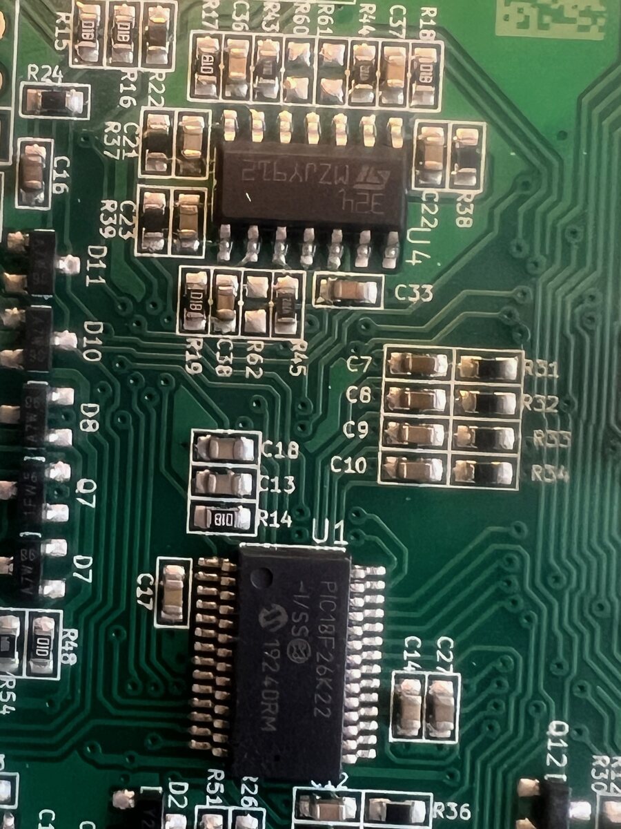
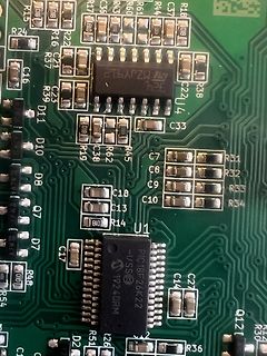
Nahaufnahme einer bestückten Leiterplatte mit Mikrocontroller
R15 R16 R22 R24 R26 R37 R38 R39 R45 R48 R51 R54 R60 R61 R62 C1 C6 C7 C8 C9 C10 C13 C14 C16 C17 C18 C21 C22 C27 C33 C36 C37 C38 C39 U1 U4 D2 D7 D8 D10 D11 Q1 Q7 Q12 19240RM PIC18F26K22 VSS
in „Abgerauchte Teile“ · Analoge Elektronik und Schaltungstechnik · · Platinenfotos
-
Datei
main.c
/ 8) - 1; // compare value: 1/15000 of CPU frequency, presc = 8 TCCR1 = (1 << CTC1) | (1 << CS12); // switch CTC Mode on, set prescaler to 8 #else OCR1C = (F_CPU / F_INTERRUPTS / 4) - 1; // compare value
in „IRMP-Anwendung“ · Mikrocontroller und Digitale Elektronik ·
-
Datei
Code.c
****************/ /*---------------------------------------------------------------- Headerdateien PIC 18f2525 ----------------------------------------------------------------*/ #include <p18cxxx.h> #include <delays.h> /*---------------------------------------------------------------- Kofiguration des
in „LCD ansteuerung mit PIC18F2525“ · Mikrocontroller und Digitale Elektronik ·
-
Datei
main.c
/* LCD SOFTWARE * ------------------------------------------------- * Hardware: * PIC PIN LCD-Pin Funktion * * 1 GND * 2 VDD +5V * 3 Kontrast (ca.8,2V) * RB4 13 4 I/OC1 * RB5 12 5 R/W * RB6 11 6 EX (enable) * RC0 16 7 DB0 * RC1 15 8 DB1 * RC2 14 9 DB2 * RC3 7 10 DB3 * RC4 6 11 DB4 * RC5 5 12 DB5 * RC6 8 13 DB6 * RC7 9 14 DB7 * RB7 10 15 I/OC2 */ // Includes #include <p18f13k22.h> // Config #pragma config FOSC = IRC #pragma config PCLKEN = OFF #pragma config BOREN = SBORDIS #pragma config BORV = 30 #
in „[PIC]LCD mit m50530 Controler“ · Mikrocontroller und Digitale Elektronik ·
-
Datei
test16F84.asm
Zeichen call datenout movlw 0x02 call datenout movlw 0x02 call datenout movlw 0x04 call datenout movlw 0x18 call datenout movlw 0x1f call datenout movlw 0x01 call datenout movlw 0x1f call datenout ;8.Byte, nun im LCD gespeichert ;**************************************************************** ; Hauptprogramm
in „Pic/LCD eigene Zeichen anzeigen“ · Mikrocontroller und Digitale Elektronik ·
-
Datei
OneWire.c
writing code uses the active drivers to raise the // pin high, if you need power after the write (e.g. DS18S20 in // parasite power mode) then set 'power' to 1, otherwise the pin will // go tri-state at the end of the write to avoid heating in a short or // other mishap. // void OneWire__write(uint8_t v, uint8
in „Böses One-Wire device“ · Mikrocontroller und Digitale Elektronik ·
-
Datei
sle4436.txt
GND (Patas 17>-<5) # ;# Resistencia Oscilacion: (Si es tipo "A" debe de llevar un Condesador de 100nF) # ;# en un -04: Entre 8K2 y 18K # ;# en un -10: Entre 6K8 y 18K # ;# en un -20: Entre 4K7 y 18K # ;# Disclaimer: Para uso educativo y NO lucrativo, no me responsabilizo del mal # ;# Uso que se le pueda
in „SLE4436 mit ASM emulieren“ · Mikrocontroller und Digitale Elektronik ·
-
Datei
sle4436.txt
GND (Patas 17>-<5) # ;# Resistencia Oscilacion: (Si es tipo "A" debe de llevar un Condesador de 100nF) # ;# en un -04: Entre 8K2 y 18K # ;# en un -10: Entre 6K8 y 18K # ;# en un -20: Entre 4K7 y 18K # ;# Disclaimer: Para uso educativo y NO lucrativo, no me responsabilizo del mal # ;# Uso que se le pueda
in „Suche Hilfe bei einem ASM CODE“ · Mikrocontroller und Digitale Elektronik ·
-
PDF
Getting_Started_with_the_Micromite.pdf
Micromite as well as the 64 and 100-pin Micromite Plus versions. You can use a number of different PIC32 microcontrollers for the 28-pin Micromite but the best is the Microchip PIC32MX170F256B-50I/SP. This is a 28-pin dual in line plastic package which can be plugged into an IC socket or a solderless
in „Suche Relais-Steuerung“ · Mikrocontroller und Digitale Elektronik ·
-
Datei
Code.txt
list p=18F46k80 ; PIC18F46K80 Configuration Bit Settings #include "p18F46K80.inc" ; CONFIG1L CONFIG RETEN = OFF ; VREG Sleep Enable bit (Ultra low-power regulator is Disabled (Controlled by REGSLP bit)) CONFIG
in „PIC18F46K80 - Probleme mit Port-Konfiguration“ · Mikrocontroller und Digitale Elektronik ·
-
PDF
slau330a.pdf
Value Package Type Device C1 47pF 0805 C2 12pF 0805 C3 DNP 0603 C4 12pF 0805 C5 10µF 0805 C6 47pF 0805 C7 100nF 0805 C8 220n 0603 C9 220n 0603 C10 10uF/6,3V 1210 C11 100n 0603 C12 100n 0805 C13 100n 0805 C14 DNP 0603 C15 10uF/6,3V 1210 C16 100n 0805 C17 470n 0805 C18 10µF 0805 C19 100nF 0805 C20 .1u 0603 C21 .1u 0603 C22 1µF 0805 C23 1µF 0805 C24 1µF 0805 C25 1µF 0805 C26 1µF 0805 C27 1µF 0805 C28 4.7uF 0805 C29 10nF 0805 C30 1µF 0805 C31 .1u 0603 C32 4.7u 0805 C33
in „Frage zu Schaltung (TI MSP430)“ · Mikrocontroller und Digitale Elektronik ·
-
PDF
slau330a.pdf
Value Package Type Device C1 47pF 0805 C2 12pF 0805 C3 DNP 0603 C4 12pF 0805 C5 10µF 0805 C6 47pF 0805 C7 100nF 0805 C8 220n 0603 C9 220n 0603 C10 10uF/6,3V 1210 C11 100n 0603 C12 100n 0805 C13 100n 0805 C14 DNP 0603 C15 10uF/6,3V 1210 C16 100n 0805 C17 470n 0805 C18 10µF 0805 C19 100nF 0805 C20 .1u 0603 C21 .1u 0603 C22 1µF 0805 C23 1µF 0805 C24 1µF 0805 C25 1µF 0805 C26 1µF 0805 C27 1µF 0805 C28 4.7uF 0805 C29 10nF 0805 C30 1µF 0805 C31 .1u 0603 C32 4.7u 0805 C33
in „MSP430 ADC sehr merkwürdige Werte“ · Mikrocontroller und Digitale Elektronik ·
-
PDF
20002234D.pdf
0.80 3.1x3.1x1.2 Where: SD3114 4.7 0.251 1.14 3.1x3.1x1.4 dV = ripple voltage SD3118 4.7 0.162 1.31 3.8x3.8x1.2 dt = On time of the N-Channel switch SD3812 4.7 0.256 1.13 3.8x3.8x1.2 (D x 1/F ) SD25 4.7 0.0467 1.83 5.0x5.0x2.5 SW ® Würth Elektronik Table 5-1 contains the recommended range for the WE-TPC
in „NRF24L01+ durch MCP1640 gestört?“ · Mikrocontroller und Digitale Elektronik ·
-
Datei
main.c
< 38.5)) || ((Temperatur >= 47.5) && (Temperatur < 48.5))) { A2 = 1; // 8 setzen B2 = 1; C2 = 1; D2 = 1; E2 = 1; F2 = 1; G2 = 1; } else if(((Temperatur >= 8.5) && (Temperatur < 9.5)) || ((Temperatur >= 18.5) && (Temperatur < 19.5)) || ((Temperatur >= 28.5) && (Temperatur <
in „PIC18F25k80 Probleme mit dem ADC“ · Mikrocontroller und Digitale Elektronik ·
-
PDF
sd20.pdf
SD20 - 20 Kanal I²C RC-Servocontroller Der SD20 ist ein vorprogrammierter PIC16F872 und läuft mit einer Geschwindigkeit von 8MHz. Positions-Steuerbefehle für bis zu 20Modellbau Servos werden über den I²C Bus an den Controller gesendet. Funktionen – Einfaches I²C Bus Protokoll
in „Servocontroller SD20 am I2C Bus - Register beschreiben“ · Mikrocontroller und Digitale Elektronik ·
-
Datei
16F877A.h
//////// Standard Header file for the PIC16F877A device //////////////// #device PIC16F877A #nolist //////// Program memory: 8192x14 Data RAM: 367 Stack: 8 //////// I/O: 33 Analog Pins: 8 //////// Data EEPROM: 256 //////// C Scratch area: 77
in „HEX-Datei erstellen“ · Mikrocontroller und Digitale Elektronik ·
-
Datei
Daten.c
*********************************** * FileName: GenProcs.c * Dependencies: GenProcs.h * Processor: PIC18F4685 * Complier: Microchip C18 * * * Author Date Comment *~~~~~~~~~~~~~~~~~~~~~~~~~~~~~~~~~~~~~~~~~~~~~~~~~~~~~~~~~~~~~~~~~~~~ * Stephan Krause 17/8/12 Version 1.0 - Initial Release **************
in „Array beschreiben schlägt fehl“ · Mikrocontroller und Digitale Elektronik ·
-
PDF
BSU_DAQ1.pdf
I3 J0 T088 GND GND GND VOffset_P8 5V TP6 GND P0 I0 8 7 Output NVN P1 I1 U8U7U11 JJ8 TT8N7 R11 3 LT1677CN8#PBF TP2 Power NL0PM PIR101 PIR102 PIU103 6 P1 R8 NAnn0 J44 J7 T7NL0PM B OJ 0 2 PIU106 PIR801 PIR802 NAnn1 P6 I6 J6 T6N4 B 2B DA
in „Nachbau TC1 Seismometer“ · Analoge Elektronik und Schaltungstechnik ·
-
PDF
Capacitive_Touch_Sensor_Design_Guide_AN2934.pdf
permittivity cover material. Example: • Touch sensor electrode diameter: 12 mm • Fingertip area model: 8 mm diameter disc • Touch cover: 1 mm plastic with relative permittivity ϵ = 2 −12 r • The vacuum permittivity ϵ0is given as 8.85 × 10 F/m → The resulting capacitance is calculated as: −3 8.85 × 10⁻¹²
in „Wie realisiert man Sensortasten?“ · Analoge Elektronik und Schaltungstechnik ·
-
Datei
picdemeth.c
define RCR 0x0C #define TCR 0x0D #define CNTR0 0x0D #define DCR 0x0E #define CNTR1 0x0E #define IMR 0x0F #define CNTR2 0x0F #define RDMAPORT 0X10 #define RSTPORT 0x18 //****************************************************************** //* RTL8019AS INITIAL REGISTER VALUES //****************************
in „Handlicher Ethernet-Controller mit SPI von Microchip“ · Mikrocontroller und Digitale Elektronik ·
-
PDF
MCP73832T.pdf
0.10 1.40 0.10 )12 0.05 ) 1.20 0.05 (10 0.00 V ( 1.00 0.00 V e e t e a 8 -0.05 p e 0.80 -0.05 p o i r i V 6 -0.10 R C 0.60 -0.10 R e 4 -0.15 u u 0.40 -0.15 u r t t t o 2 IOUT 10 mA -0.20 O u 0.20 -0.20 O S 0 C = 4.7 µF, X7R Ceramic -0.25 O 0.00 -0.25 OUT COUT= 4.7 µF, X7R
in „LiPo-Charger mit MCP73832T“ · Analoge Elektronik und Schaltungstechnik ·
-
PDF
MCP73831-2_ENG_TDS.pdf
0.10 1.40 0.10 )12 0.05 ) 1.20 0.05 (10 0.00 V ( 1.00 0.00 V e e t e a 8 -0.05 p e 0.80 -0.05 p o i r i V 6 -0.10 R C 0.60 -0.10 R e 4 -0.15 u u 0.40 -0.15 u r t t t o 2 IOUT 10 mA -0.20 O u 0.20 -0.20 O S 0 C = 4.7 µF, X7R Ceramic -0.25 O 0.00 -0.25 OUT COUT= 4.7 µF, X7R
in „LiPo-IC MCP73831 kennt keine Ladeschlussspannung“ · Analoge Elektronik und Schaltungstechnik ·
-
Datei
Daten.txt
00 09 01 00 00 00 00 00 00 00 00 00 00 50 00 00 00 00 00 00 00 00 00 00 00 00 00 00 00 00 60 E0 3E F8 00 00 00 00 00 00 00 00 00 00 00 00 00 70 00 00 00 00 00 00 00 00 00 00 02 00 08 01 24 18 80 07 00 00 00 04 00 80 00 00 00 00 3C 00 00 02 00 90 00 00 01 0B 8E 08 48 0F 07 40 0F 8D 00 00 00 00 A0 00
-
Datei
LCD.c
*******************************************\ * Dateiname : * Autor : * Projekt : * * * Prozessor : PIC 18F1330 * SW-Werkzeug : C18 Compiler * * Datum: Autor: Version: * 22.02.2011 V1.0 * *********************************************************************************** * Pinnbelegung: * * PIN_A4 //Display_RS
in „Probleme mit PIC und LCD“ · Mikrocontroller und Digitale Elektronik ·
-
Datei
probieren.asm
Anzeige ; Überarbeitet Version von Marco Reinke (DG1YIQ) ; Features: Festtext ; Anpassung an Atmega 8 von PIC 16F88 ; Version v0.2 .include "m8def.inc" ;Include Datei Atmega8 ;--- Reset und Interruptvectoren; VNr. Bezeichnung begin: rjmp main ; 1 Power ON RESET reti ; 2 Int0- Interrupt reti ; 3 Int1-
in „Hat schonmal einer ein Opel TID ->erfolgreich<-angesteuert ?“ · Mikrocontroller und Digitale Elektronik ·
-
Datei
Nuforce_P9_-_Pinbeschreibung_Funktionsbeschreibung.txt
Beschreibung der Microcontroller-Pins U1, U2 U1 18-poliges Gehäuse: Pin 1, Pin 18 -> Wischeingänge vom Impulsdrehgeber Volume Pin 8 -> Tastereingang vom Impulsdrehgeber Volume, kann als Mutefunktion genutzt werden. Pin 2, Pin 3, Pin 9 -> Ausgänge H-Brücke
in „Unbekannten Controller identifizieren“ · Mikrocontroller und Digitale Elektronik ·
-
Datei
Shorttimer.c
** ************************************************************************************ #define MX_PIC //Definitionen für Microcontroller #define P16F628A #define MX_EE #define MX_EE_TYPE1 #define MX_EE_SIZE 128 #define MX_UART #define MX_UART_B #define MX_UART_TX 2 #define MX_UART_RX 1 #define MX_PWM
in „LED Ausgabe in eine Zählschleife integrieren ohne Zeit zu verlieren“ · Mikrocontroller und Digitale Elektronik ·
-
PDF
Binaeruhr.pdf
SW1 SW2 RA4 RB2 RA5 RB1 Taster Taster der Uhr VSS RB0 RA7/OSC1 VDD RA6/OSC2 VSS2 C1 J1 RC0 RC7 100nF RC1 RC6 Eingang 1Hz C RC3 RC4 C Signal PIC18F25K22 HDR1X2 Ω Ω Ω Ω Ω Ω Ω Ω Ω Ω Ω Ω Ω Ω Ω Ω Ω 7 7 7 7 7 7 7 7 7 7 7 7 7 7 7 7 7 4 4 4 4 4 4 4 4 4 4 4 4 4 4 4 4 4 1 1 D R D R D R D R D R D R D R D R D 1
in „Seminarprojekt Binäruhr, passenden µC gesucht“ · Mikrocontroller und Digitale Elektronik ·
-
PDF
D865GBF_D865GLC_TechProdSpec.pdf
Board D865GBF/D865GLC. Refer to the ICH5 data sheet for dynamic addressing information. 0170 - 0177 8 bytes Secondary Parallel ATE IDE channel command block 01F0 - 01F7 8 bytes Primary Parallel ATE IDE channel command block 0228 - 022F (Note 1) 8 bytes LPT3 (Note 1) 0278 - 027F 8 bytes LPT2 02E8 - 02EF
in „VS: Intel D865GBF, Pentium 4 (3GHz/1M/800) SL7PM, Matrox G45“ · Markt ·
-
PDF
MCP73831.pdf
temperature range of -40°C to +85°C. 500 mA Li-Ion Battery Charger Package Types VIN 4 VDD VBAT 3 4.7 μF 4.7 μF + Li-Ion 8-Lead DFN - Cell (2 mm x 3 mm) 5 SOT23-5 PROG V 1 8 PROG STAT 1 5 PROG DD 470Ω 2 kΩ V SS2 V DD 2 7 NC 1 STAT VSS 2 V BAT3 4 V DD VBAT 3 6 V SS MCP73831 VBAT 4 5 STAT © 2005 Microchip
in „Akku Ladetechnik“ · Mikrocontroller und Digitale Elektronik ·
-
PDF
lcd1.pdf
0 0 0 0 1 D U B 08 to 0F Display/Cursor Shift 0 0 0 1 D / C R / L x x 10 to 1F Function Set 0 0 1 8 / 4 2 / 1 10 / 7 x x 20 to 3F Set CGRAM Address 0 1 A A A A A A 40 to 7F Set Display Address 1 A A A A A A A 80 to FF 1/ D:
in „LCD ohne Datenblatt oder Hinweise zur Pinbelegung“ · Mikrocontroller und Digitale Elektronik ·
-
 Bild
Screenshot eines Online-Forums für Mikrocontroller und Elektronik
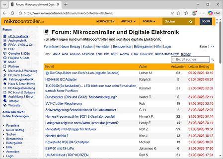
Benutzerliste | Bildergalerie | Hilfe | Logout (magnetus) Seite 1 >> Filter: ARM AVR Arduino MSP430 ESP PIC 8051 AVR32 C16x PowerPC R8C/M16C/M32C [keiner] Im Betreff suchen Die/Chip-Bilder von Richi's Lab (digitale Bauteile) Lothar M. 63 05.02.2026 13:10 HD44780 12C Adapter Ralph S. 8 01.04.2026 00:24 TLC5940
in „Seltsamer Link zu embdev.net“ · www.mikrocontroller.net · · Screenshots
-
Datei
1wire_Software_18F.inc
LIST ; Standard-File für das 1-wire-Software-Kommunikation am PORT_A für PIC 18F NOLIST ;========================================================================== ; ; ; ;========================================================================== ;============================
in „Tempsensor DS18B20 1-wire und PIC“ · Mikrocontroller und Digitale Elektronik ·
-
 Bild
Screenshot eines deutschsprachigen Elektronik-Forums
Suchen | Anmelden | Benutzerliste | Bildergalerie | Hilfe | Login Filter: ARM AVR Arduino MSP430 ESP PIC 8051 AVR32 PowerPC R8/M16/M32C [keiner] Betreff | Autor | Antworten | Letzter Beitrag Die/Chip-Builder von Richi's Lab (digitale Bauteile) | Lothar M. | 63 | 05.02.2026 13:10 HD44780 I2C Adapter | Ralph
in „Seltsamer Link zu embdev.net“ · www.mikrocontroller.net · · Screenshots
-
 Bild
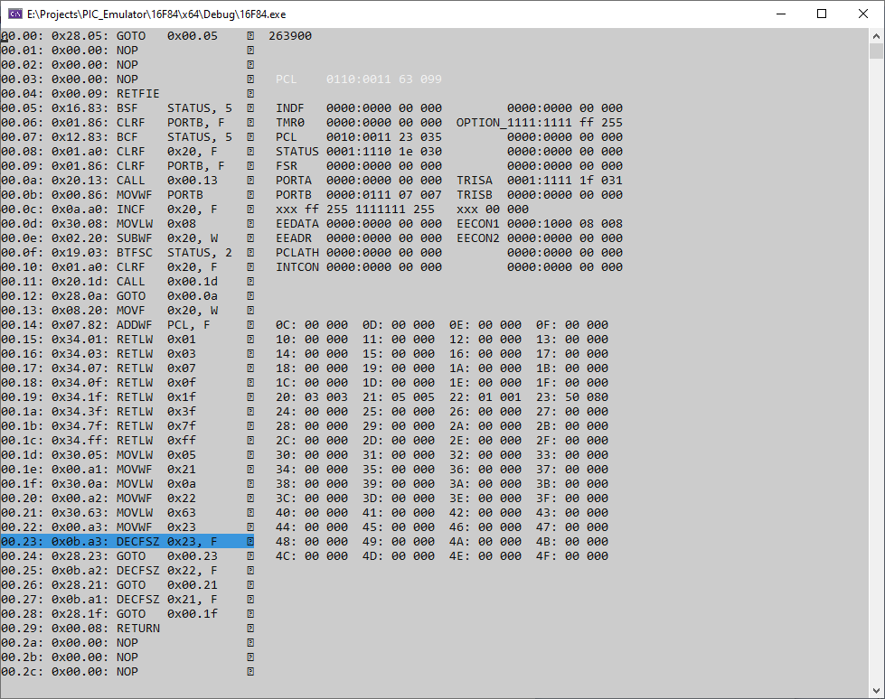
Screenshot eines Mikrocontroller-Assembler-Debuggers
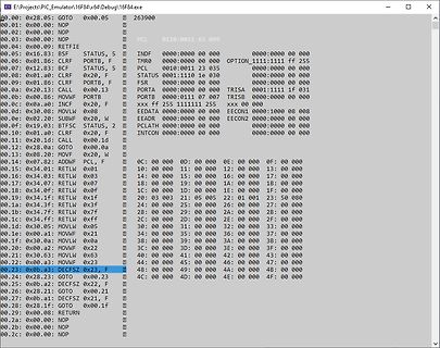
E:\projects\PIC_Emulator16F8x\Debug\16F84.exe 00.00: 0x28: GOTO NOP 00.02: 0x00: NOP 00.03: 0x00: NOP 00.04: 0x00: RETFIE STATUS, 5 00.05: 0x16: CLRF PORTB, F 00.06: 0x01: BSF STATUS, 5 00.07: 0x12: BSF PORTB, F 00.08: 0x01: CLRF PORTA 00.09: 0x13: CALL 0x00.13 00.10: 0x01: CLRF PORTB, F 00.11: 0x02: SUBWF STATUS, 2 00.12: 0x0a: BTFSC PORTA, 0 00.13: 0x08: GOTO 0x00.1a 00.14: 0x78: MOVF PORTB, F 00.15: 0x34: RETLW 0x07 00.16: 0x34: RETLW 0x07 00.17: 0x34: RETLW 0x07 00.18: 0x34: RETLW
in „Emulator Microchip PIC16F84“ · Projekte & Code · · Screenshots
-
Datei
main.c
#include <p18f23k22.h> //#include <usart.h> #include <timers.h> #pragma config FOSC = INTIO67 #pragma config WDTEN = OFF #pragma config MCLRE = EXTMCLR //************* Defines *************************************
in „PIC18-Projekt restartet unerklärlich“ · Mikrocontroller und Digitale Elektronik ·
-
Datei
Quelltext.txt
#include </usr/share/sdcc/include/pic16/pic18f1320.h> #define pause_us() __asm nop __endasm XT-Frequenz code char at __CONFIG1H _conf0 = _IESO_OFF_1H & _FCMEN_OFF_1H & _OSC_XT_1H; code char at __CONFIG2L _conf1 = _BODEN_OFF_2L & _PUT_OFF
in „PIC18F1320 mit DS1821 Temperatur Sensor keine Daten“ · Mikrocontroller und Digitale Elektronik ·
-
 Bild
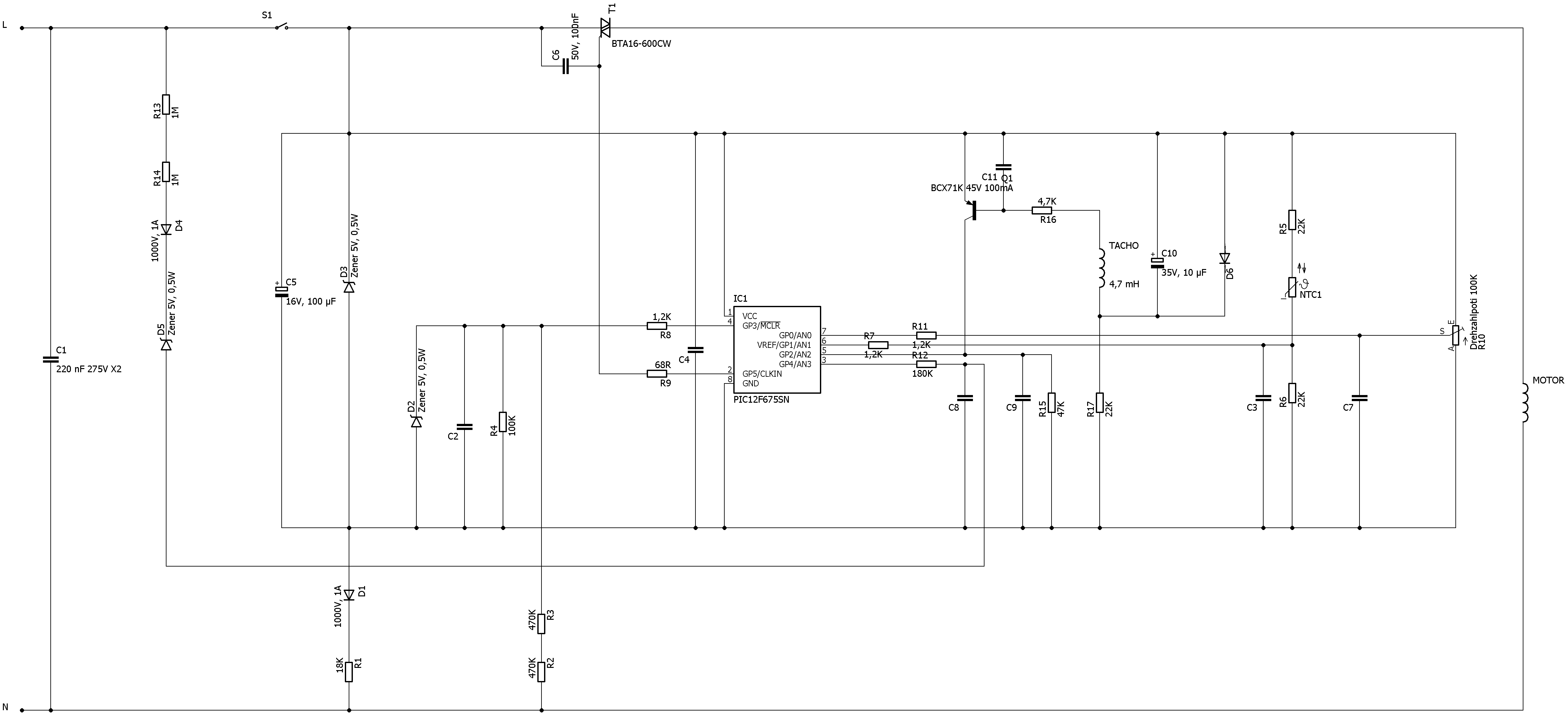
Schaltplan einer Motorsteuerung mit PIC12F675N
L S1 C6 50V 100uF BTA16-600CW R13 1M R14 1A D4 Zener 5V 0,5W C5 16V 100uF D3 Zener 5V 0,5W C1 220 nF 275V X2 1000V 1A D1 18K R1 470K R2 470K R3 R8 1,2K R9 68R IC1 VCC GP0/AN3 VREF/GP4 GP0/AN3 GP1/AN2 GP2/AN3 GP3/AN0 CLKIN GND PIC12F675N R7 1,2K R11 180K C9 100nF R16 4,7K C10 35V 10uF R5 2k R15 4,7K R17 2,2K R12 2k C7 R10 100K N MOTOR NTC1
in „Kress/AMB Fräsmotor 1050-FME-1 Regelelektronik tauschen“ · Analoge Elektronik und Schaltungstechnik · · Schaltpläne

-
PDF
TDS220_Display.pdf
~ Supply current (Logic) IDD VDDZ5$VEEZ-24V – 7 9 mA ~ Supplycurrent(LCD) IXX VDD-V.=21, 5V – 5.5 8.8 mA – ~ Powerconsumption(LCD) PdCD F=80Hz(Note 2) 167 208 mw ~ Start voltage (B/L) VFTS W W * ‘18(1 V rs A Supply voltage(B/L] V,TL - LMOOM & 250 275 300 Vrills SUPPIY current (B/L) IFT ~ 4 5 E m Arins
-
PDF
Sharp_LM32P07_Display.pdf
~ Supply current (Logic) IDD VDDZ5$VEEZ-24V – 7 9 mA ~ Supplycurrent(LCD) IXX VDD-V.=21, 5V – 5.5 8.8 mA – ~ Powerconsumption(LCD) PdCD F=80Hz(Note 2) 167 208 mw ~ Start voltage (B/L) VFTS W W * ‘18(1 V rs A Supply voltage(B/L] V,TL - LMOOM & 250 275 300 Vrills SUPPIY current (B/L) IFT ~ 4 5 E m Arins
-
 Bild
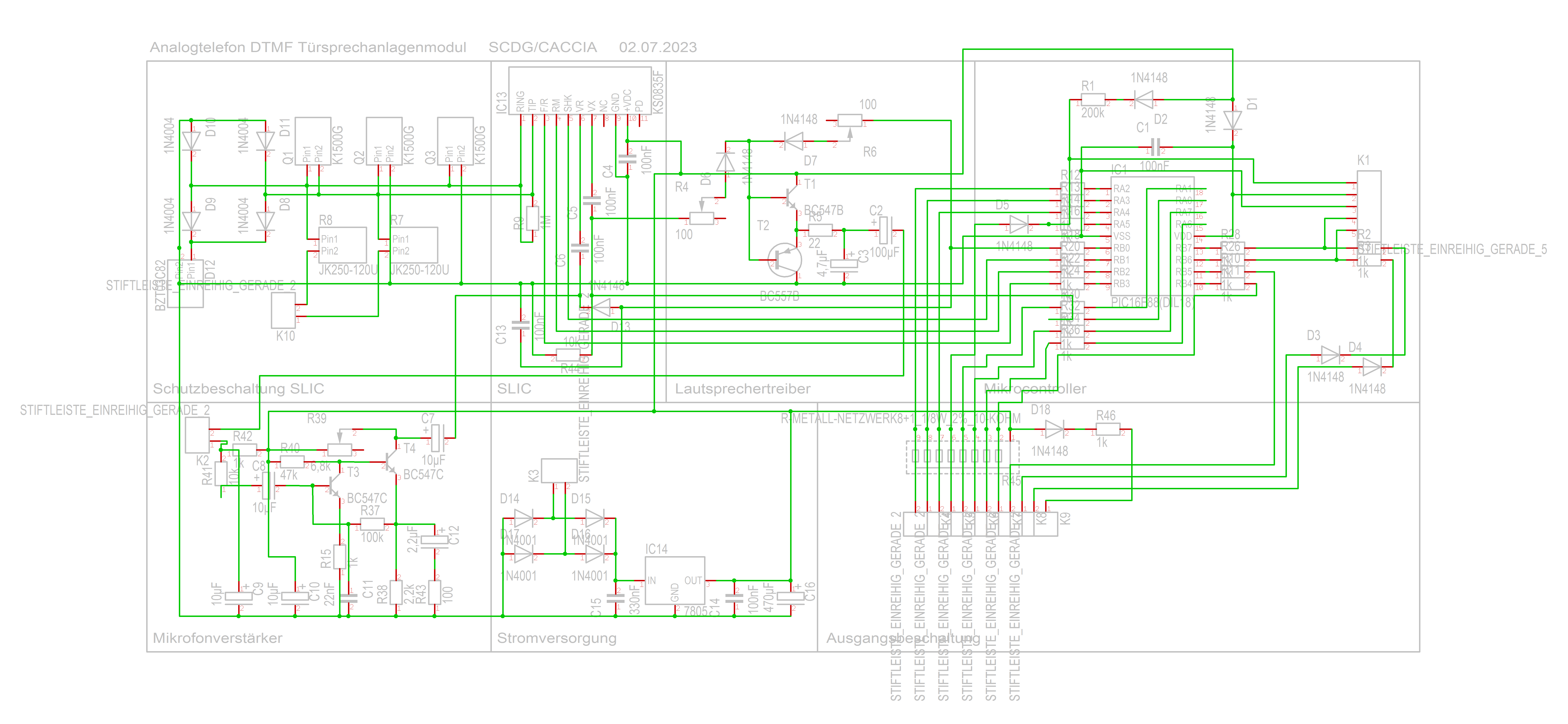
Schaltplan eines Analogtelefon DTMF Sprechanlagenmoduls
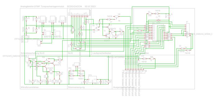
Analogtelefon DTMF Sprechanlagenmodul SCDG/CACCIA 02.07.2023 1N4148 100 200k R1 1N4148 D1 K1 100uF C1 1N4148 D7 R6 T1 BC547B C2 100uF R2 R3 R4 R5 R6 R7 R8 R9 R10 R11 R12 R13 R14 R15 R16 R17 R18 R19 R20 R21 R22 R23 R24 R25 R26 R27 R28 R29 R30 R31 R32 R33 R34 R35 R36 R37 R38 R39 R40 R41 R42 R43 R44
in „DTMF Türsprechmodul mit PIC16F8x - Prüfung und Programmierung“ · Mikrocontroller und Digitale Elektronik · · Schaltpläne
-
Datei
LCD.c
0xC3, 0x30, 0x63, 0x30, 0x33, 0x30, 0x1E, 0x18, 0xFE, 0x1F, 0xF8, 0x07, // "0" 0x00, 0x00, 0x00, 0x00, 0x00, 0x00, 0x0C, 0x30, 0x0C, 0x30, 0x0E, 0x30, 0xFF, 0x3F, 0xFF, 0x3F, 0x00, 0x30, 0x00, 0x30, 0x00, 0x30, 0x00, 0x00, // "1" 0x00, 0x00, 0x1C
in „Mini-Farbdisplay (+mehr) für 1 Euro“ · Mikrocontroller und Digitale Elektronik ·
-
PDF
EMS_V2_Schaltplan.pdf
1 D2 1 2 SJ3 100n 2 E S 8 D7 EMS_GND 1N4148SMD MCP2551SN D10 E 1 T1 C18 PSD2CAN N EMS_GND BC857ASMD GND 1 k 5 R 4 _ 5 6 0 M _ EMS_TX R 2 E M 1 1 1 1 RA5 GND E 9 9 9 9 1N4148SMD EMS_5V 0 2 2 2 2 1 7 0 R R R R 8 B 1 k 4 2 IC6 9
in „Buderus EMS-"Gateway" mit PIC18F / Sammelbestellung“ · Haus & Smart Home ·
-
Datei
demo1c.asm
DEMO1: Simple Running light for testing LD1...LD5 * ;* DEMO1: Program for testing K8048/VM111 with PIC16F627! * ;************************************************************************** ;* (C) VELLEMAN Components,2003 All rights reserved * ;**********************************************************
in „Probleme bei Verwendung von RA4 als Ausgang (pic16f84)“ · Mikrocontroller und Digitale Elektronik ·