Suchergebnisse für "A109"
°C 600°C Diameter Resistance Surface Load Surface Load Surface Load Surface Load in mm in Ω/m I in A in W/cm² I inA in W/cm² I inA in W/cm² I inA in W/cm² 0,020 1560 0,0964 23,0 0,110 30,1 0,133 44,2 0,144 51,3 0,022 1290 0,109 22,2 0,123 28,3 0,149 41,4 0,161 48,3 0,025 998 0,124 19,6 0,143 25,9 0,173
in
„Temperatur des Heizdrahtes berechnen“
·
Analoge Elektronik und Schaltungstechnik
·
30.01.2023 17:43
2 - M102 NJM2120 C43 R64 R65 R72 3 1 2 + 3 3 A M224 2.7K 22K Q1 33K - 2 5 J202 C47 IC2A R77 R78 - NJM4558DD 7 + M223 R74 R61 B 47K 6 - 33K 47K 100K 4 1 VR10 -15V + C45 A 1M C51 C53 C39 SW4 10/50V 101P CPS-2254 M473 VR12 M223 C55 LED6 C48 B100K M104
in
„Marshall G100R CD“
·
Analoge Elektronik und Schaltungstechnik
·
12.09.2018 11:11
Bild
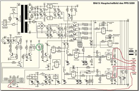
Bild 5: Hauptschaltbild des PPS 5330 ST100 ST1 Netzscaler ST100 230V~50Hz C100 1V 10uF ST1 6V 0,33A D1 1N4001 D2 1N4001 D3 1N4001 D4 1N4001 C1 1uF C2 1uF C3 4,7uF C4 10uF IC1 7805 5V C5 10uF C6 10uF C7 10uF C8 10uF C17 10uF +5V ST6 R56 Messverstärker Strom IC8 NPN R55 10k R57 10k R58 10k R59 10k R60
in
„PPS5330 Labor-Netzteil hack“
·
Mikrocontroller und Digitale Elektronik
·
27.04.2024 23:55
·
Schaltpläne
Bild
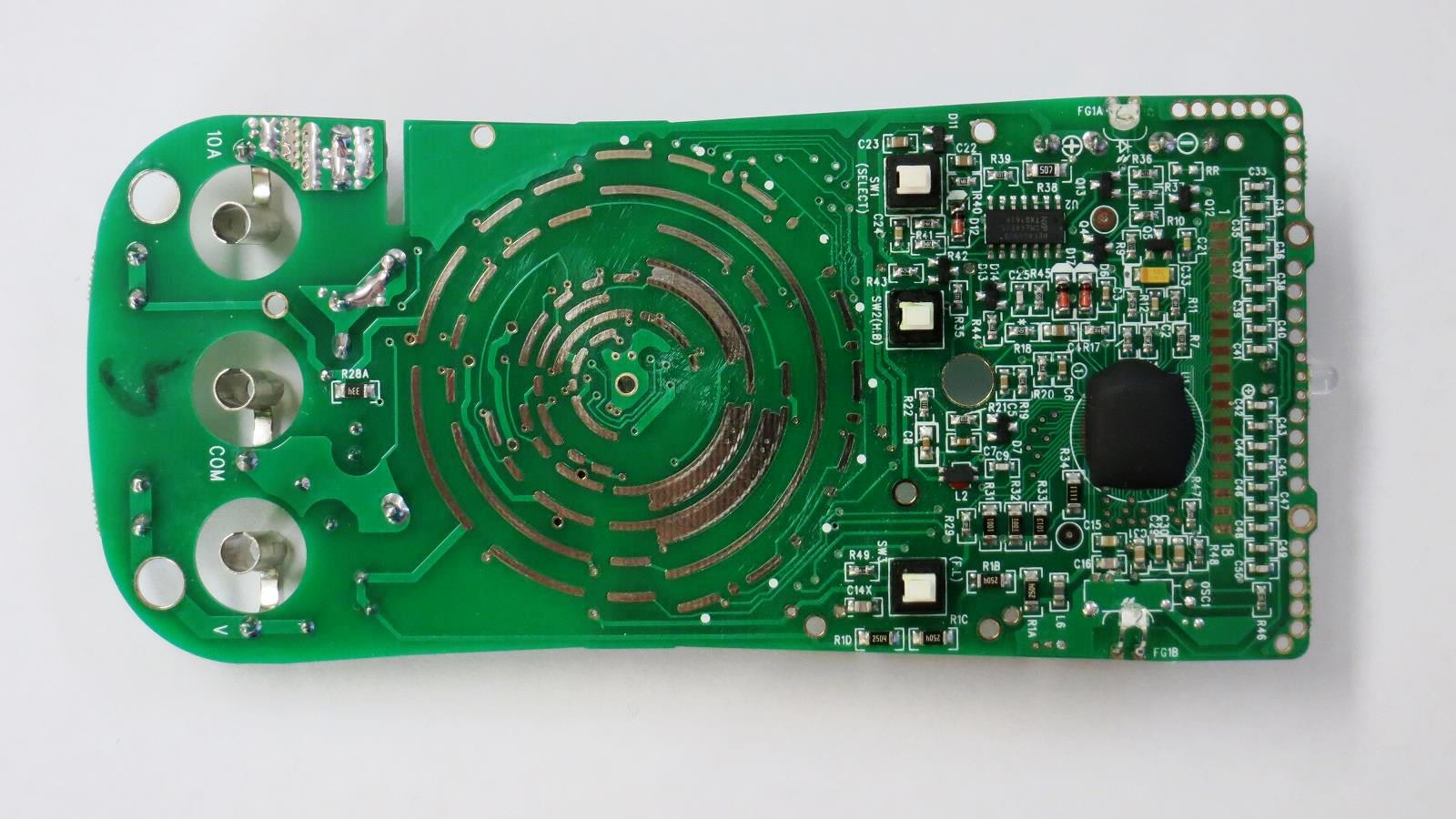
COM 10A V SELECT SW2(H,B) C24 C33 R41 R42 R43 R44 R45 R46 R47 R48 R49 R50 R51 R52 R53 R54 R55 R56 R57 R58 R59 R60 R61 R62 R63 R64 R65 R66 R67 R68 R69 R70 R71 R72 R73 R74 R75 R76 R77 R78 R79 R80 R81 R82 R83 R84
in
„Voltcraft VC175 lässt sich nicht einschalten! Defekt!?“
·
Analoge Elektronik und Schaltungstechnik
·
05.09.2024 09:26
·
Platinenfotos
Bild
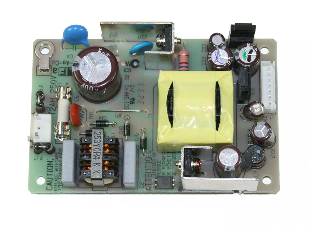
A 9-Cu 250V 2AH 400V C5 C6 C7 C8 C9 C10 C11 C12 C13 C14 C15 C16 C17 C18 C19 C20 C21 C22 C23 C24 C25 C26 C27 C28 C29 C30 C31 C32 C33 C34 C35 C36 C37 C38 C39 C40 C41 C42 C43 C44 C45 C46 C47 C48 C49 C50 C51
in
„Roland G-70 fährt nicht hoch.“
·
Analoge Elektronik und Schaltungstechnik
·
13.03.2025 18:10
·
Platinenfotos
Bild
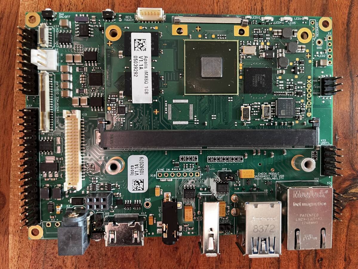
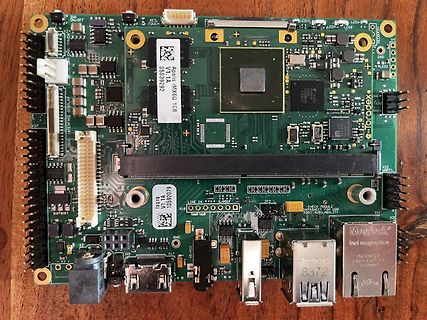
Apalis IMX6D 1GB V1.A 05039292 LED1 bis LED5 LINE IN X20 X22 X27 X18 X19 X3 X11 X24 X25 X26 X28 X29 X30 X31 X32 X33 X34 X35 X36 X37 X38 X39 X40 X41 X42 X43 X44 X45 X46 X47 X48 X49 X50 X51 X52 X53 X54 X55 X56 X57 X58 X59 X60
in
„[V] Toradex Ixora + Apalis IMX6 Quad 1GB Embedded Board“
·
Markt
·
27.01.2024 14:46
·
Platinenfotos
Bild
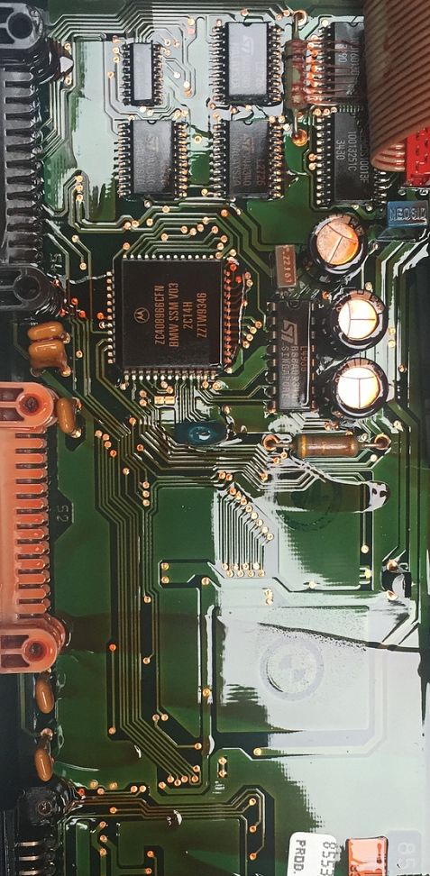
ZCA0966CFN BMW 355A V03 ZZIW9346 L101 103J5C 100pF L102 103J5C 100pF L103 103J5C 100pF L104 103J5C 100pF L105 103J5C 100pF L106 103J5C 100pF L107 103J5C 100pF L108 103J5C 100pF L109 103J5C 100pF L110 103J5C 100pF L111 103J5C
in
„? Controlleridentifikation“
·
Mikrocontroller und Digitale Elektronik
·
24.06.2025 20:06
·
Platinenfotos
Bild
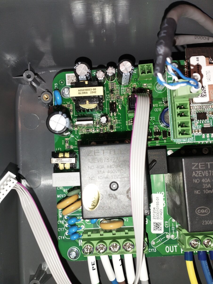
A 05010053-00 GLORIA 2342 CY5 C42 LED1 LED2 LED3 D55 R13 N10 CE15 R13 R14 R15 R16 R17 R18 R19 R20 R21 R22 R23 R24 R25 R26 R27 R28 R29 R30 R31 R32 R33 R34 R35 R36 R37 R38 R39 R40 R41 R42 R43 R44 R45 R46
in
„[Wallbox] AlphaESS SMILE-G3-EVCT11“
·
Mikrocontroller und Digitale Elektronik
·
26.04.2025 15:04
·
Platinenfotos
Hardware: PD6: Signaleingang ' PD1-PD4: 7-segment - Ziffer - Select ' PB0-PB6: 7-segment - Segment A bis G $regfile = "2313def.dat" $crystal = 8000000 Ddrb = &B11111111 Ddrd = &B00111111 Dim Icount As Long At &H60 Dim Wcountlo As Word At &H60 Overlay Dim Wcounthi As Word At &H62 Overlay Dim Zahl1 As
in
„Drehzahlmesser 4 mal 7-segment mit 90S2313“
·
Projekte & Code
·
11.10.2006 11:07
z.B. WinAmp ist spricht für sich. Spezifikationen des Displays: Abmessungen: - Gehäuse: B=167mm x H=109 mm x T=9mm Anzeigefläche: B=120mm x H=92mm Auflösung: - 320(horizontal) x 240 Pixel (vertikal) Beleuchtung: - weiss, CCFL (Cold Cathode Fluorescent Lamp) - Anzeigefarbe kann durch Einsatz von Farbfolien
in
„Verkaufe S1D13305F00A (SED1335F)“
·
Markt
·
11.10.2006 12:01
Bild
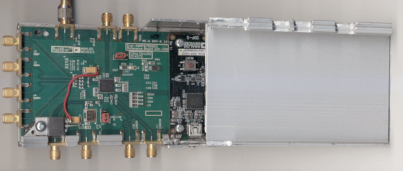
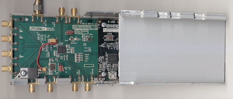
RoHS ANALOG DEVICES Eval-ADRF7555D Reference board with USB NC-A 84Y-0 14 SDP-S J2 IBBP J3 IBBN J4 QBBN R67 R68 R69 R70 R71 R72 DUT ADET MUXOUT C51 C52 C53 C54 C55 C56 C57 C58 C59 C60 C61 C62 C63 C64 C65 C66 C67 C68 C69 C70 C71 C72 C73 C74 C75 C76 C77 C78 C79 C80
in
„Benutzt hier jemand Bopla Filotec Gehäuse?“
·
Mechanik, Gehäuse, Werkzeug
·
21.07.2023 16:25
·
Platinenfotos
Bild
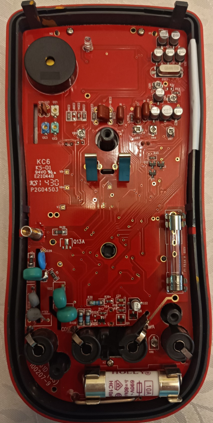
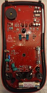
KC6 KS-01 94V0 E210448 P2G04503 Q13A R30 R31 R32 R33 R34 R35 R36 R37 R38 R39 R40 R41 R42 R43 R44 R45 R46 R47 R48 R49 R50 R51 R52 R53 R54 R55 R56 R57 R58 R59 R60 R61 R62 R63 R64 R65 R66 R67 R68 R69 R70 R71 R72 R73 R74 R75 R76 R77 R78 R79
in
„Uni-T UT61D nachjustieren“
·
Analoge Elektronik und Schaltungstechnik
·
07.05.2026 07:33
·
Platinenfotos
PIDISP106R1 DISP_R1 PIIC20E12 32 DISP R1 7 DISP_R2 DISP_R2 B15 IO_L1N_A 24_VREF_1 PIDISPHSYNC R2 PIDISP107 PIIC20BIO_L29P_A 23_M1A 13_1 PIDISPVSYNC R3 PIDISP108R3 DISP_R3 PIIC20BIO_L29N_A 22_M1A 14_1 R4 PIDISP109 R4 DISP_R4 PIIC20FIO_L30P_A 21_M1RESET_1 PIDISP1010R5 DISP_R5 PIIC20G11
in
„[Suche] Interessierte(n) an Projekt (ARM/FPGA)“
·
Mikrocontroller und Digitale Elektronik
·
02.04.2012 18:15
socket[ 0] ACK: 1168 SEQ: 40707 -> 0 bytes in HTTP: SEQ-SEQ_OFFSET_DATA = 1092 7 1- Ò Ò zÒ ªê€ž ¹ á ¹rrþLOG : requestet temp => 64 -> buf[ 0.0] LOG : requestet temp => 48 -> buf[- 8.0] LOG : requestet temp => 152 -> buf[ 44.0] ret= 0 last data byte sent = 1714 TCP : socket[ 0] ACK: 1714 SEQ: 40707 -
in
„winziger Webserver mit enc28j60+mega32“
·
Mikrocontroller und Digitale Elektronik
·
12.10.2006 02:09
received ($0067, 103 ms). Bit #28. Bit '0' received ($006B, 107 ms). Bit #29. Bit '0' received ($006A , 106 ms). Bit #30. Bit '0' received ($005A , 90 ms). Bit #31. Bit '1' received ($00CA, 203 ms). Bit #32. Bit '0' received ($005D, 93 ms). Bit #33. Bit '1' received ($00B2, 179 ms). Bit #34. Bit '0' received ($006A , 106 ms). Bit #35. Bit '0' received ($006F, 111 ms). Bit #36. Bit '0' received ($006D, 109 ms). Bit #37. Bit '0' received ($0061, 97 ms). Bit #38. Bit '1' received ($00C3, 196 ms). Bit #39. Bit '0' received
in
„DCF77 - Puls der Sekunde 0 nur 65 ms?“
·
HF, Funk und Felder
·
04.11.2023 14:37
1 2 3 4 5 6 Option LAN Würth 742792038 +3.3D L21_10 PIL210101 PIL210102 10 A CO21_1 U21_10 A 10100n LA_CLK25 PIU21OUT GND PIU210102 GND 03 0 0 R21_103 2 R21_10 PIU21VDD4 E/D PIU210101 49R9 O12 R 10R GND 03 R 0 4 0 Würth 742792038 25MHz +3.3D L21_404 C21_40 TX+ PIT21010TDP TXP
in
„TEKWAY DST1xx2B Oszilloskop“
·
Mikrocontroller und Digitale Elektronik
·
21.06.2013 19:44
+5VDIG 1 2 3 4 +5VDIG 1 1 P Einer Zehner Hunderter R1 10k A A 1 15 2 35 0 0 S1 0 S2 0 S3 R P P P 1 P DGND 0 R2 C C C +24V P 220 0 C1 0 0.1µF 2 1 1 2 4 3 4 1 1 2 4 3 4 11 224 83 4 P R 1 1 1 1 2 2 2 2 3 3 3 3 6 7 P P P P P P P P P P P P P P0K106 P0K107 DGND 1 2
in
„PGA2310/CS3310 mit Bascom via SPI?“
·
Mikrocontroller und Digitale Elektronik
·
01.08.2007 21:20
+5VDIG 1 2 3 4 +5VDIG 1 1 P Einer Zehner Hunderter R1 10k A A 1 15 2 35 0 0 S1 0 S2 0 S3 R P P P 1 P DGND 0 R2 C C C +24V P 220 0 C1 0 0.1µF 2 1 1 2 4 3 4 1 1 2 4 3 4 11 224 83 4 P R 1 1 1 1 2 2 2 2 3 3 3 3 6 7 P P P P P P P P P P P P P P0K106 P0K107 DGND 1 2
in
„Digipoti fernsteuern“
·
Mikrocontroller und Digitale Elektronik
·
09.09.2007 11:46
Als Regelverstärker für Konstantspannungs-und Konstantstrombetrieb dienen je ein OperationsverstärkerA 109 . Die Eingänge der Operationsverstärker sind nach außen geführt, dadurch lassen sich verschiedene Betriebsarten des Gerätes realisieren. Um einen geringen Temperaturkoeffizienten und hohe Langzeitstabilität
in
„Das Statron 3217/16 Projekt“
·
Analoge Elektronik und Schaltungstechnik
·
27.10.2025 17:23
66 Write A -ACK 05 D-ACK E0 D-ACK CD D-ACK Packet # Name TimeStamp Address Write A -ACK Data D-ACK Data D-ACK Data D-ACK 6 Bus1(I2C) 109 .4369ms 66 Write A -ACK 05 D-ACK 20 D-ACK 20 D-ACK Packet # Name TimeStamp Address
in
„[AVR] FM-Transmitter für 1,50EUR --> Ansteuerung?“
·
Mikrocontroller und Digitale Elektronik
·
25.03.2012 22:15
Frequency 50-60 Hz 50-60 Hz Operating Line Frequency Range 47-63 Hz 47-63 Hz Rated Input Current 8A /4A 6A /3A Heat Dissipation 1575 BTU/hr maximum 315BTU/hr typical 1260 BTU/hr maximum 315 BTU/hr typical Power Supply Fan Variable speed fan Variable speed fan Energy Star Compliant YES YES FEMP Standby
in
„PC bootet nicht nach cpu Tausch“
·
PC Hard- und Software
·
26.01.2024 18:16
Frequency 50-60 Hz 50-60 Hz Operating Line Frequency Range 47-63 Hz 47-63 Hz Rated Input Current 8A /4A 6A /3A Heat Dissipation 1575 BTU/hr maximum 315BTU/hr typical 1260 BTU/hr maximum 315 BTU/hr typical Power Supply Fan Variable speed fan Variable speed fan Energy Star Compliant YES YES FEMP Standby
in
„PC bootet nicht nach cpu Tausch“
·
PC Hard- und Software
·
26.01.2024 18:17
1xAANMHpalka" 9Ma208 0Ma218 ubeaneGeruhzuand nchaung5h@5mA nadngm10mA Enaungt10mA Tmee. V mAh imel. V mh 0000 ,8 0 00:0 ,4 0 0001 ,7 0 00:1 ,2 0 0006 ,6 0 00:6 ,1 0 0001 ,6 1 00:1 ,1 1 0006 ,6 1 00:6 ,1 1 0011 ,6 2 00:1 ,1 2 0016 ,6 2 00:6 ,1 2 0011 ,6 3 00:
in
„Ladewirkungsgrad NiMH“
·
Analoge Elektronik und Schaltungstechnik
·
18.05.2018 22:09
// // Boot Block ATmega Self Programmer (as by Atmel APP Note 109 ) // #device 163 cpu.clock = 3580000; #include <sys\regs16> use R19 as WREG; var i,j,cmd, tmp: byte; // BOOTSZ = org $1C00 // // Main in Boot Block! // // pull ups { // isp163 portb.3 := 1; portb.2 :
in
„Bootloader für ATMega163“
·
Mikrocontroller und Digitale Elektronik
·
11.10.2006 11:17
000000000001111 61 '=' 000000000010000 62 '>' 00000010001 63 '?' 000000000001110 64 '@' 000000000001100 65 'A ' 1010 66 'B' 0001111 67 'C' 0000001001 68 'D' 00001010 69 'E' 0010000 70 'F' 00010001 71 'G' 00001110 72 'H' 0001110 73 'I' 000000110 74 'J' 000001011 75 'K' 0001101 76 'L' 0001100 77 'M' 00010000 78
in
„Unbekanntes Textformat“
·
Softwareentwicklung
·
05.10.2015 16:13
VCC VCC COP COU R2 I2 P1 U4 COR COR 2 PIP102 PIU401 IN OUT PIU402 R3 R4 VCC 1 PIP101 GND Res2 Res2 A C0 C1C 20 COC 02 OC3 R1100K I1100K U2U2 A Header 2 Cap Pol1 2 I03 C3 PIU206 SCL VCC PIU208 VCC C2 100uF 21 Cap 01 Cap Y2Y2 PIU205 SDA VBAT PIU203 100nF L7805CV 100nF PIY202 PIY201 PIU201 X1 PIU202 X2
in
„AVR Wecker mit Netzwerk“
·
Mikrocontroller und Digitale Elektronik
·
12.11.2010 14:12
X2 X1 1200 ~ 15000 0,90 0,95 1,00 1,00 0.5 Lifetime Multiplier 0.0 40 50 60 70 80 90 100 110 T (˚C) A IA= actual ripple current Rt 100kHz, I = rated ripple current at 100kHz, 105°C Multiplier of Useful Life as a function of ambient temperature and ripple current load Direct Contact & Support: Jianghai
in
„Empfehlung für Low-ESR LONG LIFE Elkos?“
·
Mikrocontroller und Digitale Elektronik
·
01.09.2011 18:15
r1,#0dh,X10a 1 X10a 1: jc X10c5 inc dptr movx a ,@dptr mov r6,a jb acc.7,X10cd cjne a ,#20h,X10ac X10ac: jnc X10b1 cjne a ,#0dh,X10cd X10b1: cjne a ,#22h,X10bd acall X1111 X10b6: acall X1113 cjne a ,#22h,X10b6 sjmp X109 e
in
„Basic für 80C31“
·
Mikrocontroller und Digitale Elektronik
·
30.10.2015 15:05
.... 94 10.4 BitBang und die Emulation anderer Schnittstellen ................ 97 11 Ein einfacher A /D-Wandler mit BitBang ....................................... 99 11.1 A /D-Wandler-Konzept ................................................... 99 Inhalt 11 11.2 Schaltbild A /D-Wandler mit einem Komparator
in
„Buderus EMS-"Gateway" mit PIC18F / Sammelbestellung“
·
Haus & Smart Home
·
09.03.2011 14:27
1 2 3 4 5 6 A A COoo1 PCB LOGO Texas Instruments CLoo C1 PCB PI1 PC0 LOGO 1000pF FCC disclaimer J1 PCB Number: PMP15006 GND ISOGND P1 O PCR PIJ11 5VSEC PCB Rev: E1 COoo3 C2 R1 PIJ12 P 10µF 1.00 CO!C1 PCB CO P HB3902U
in
„Flybuck Konverter“
·
Analoge Elektronik und Schaltungstechnik
·
18.09.2019 10:39
Description Pin # Description Pin # Description Pin # Description 1 TDO 37 USBD-2 73 P2.12/SD_DAT2 109 P0.9/MOSI1/E6* 2 N/A 38 N/A 74 N/A 110 N/A 3 TDI 39 N/A 75 P2.11/SD_DAT1 111 P0.8/MISO1/E8* 4 TMS 40 VBUS 76 BL#/P2.10/E0* 112 P0.7/SCK1/E10* 5 TRST# 41 VDD1 77 VDD3 113 P0.6/SSEL1/E12* 6 VCC 42 P0.29
in
„Arm7 (Usbizi) über SPI LCD“
·
Mikrocontroller und Digitale Elektronik
·
02.11.2009 10:28
DD N C D D D AT24C512 µC2SIM A G A A A A A / / /7 G V 0 1 2 F F F FC C CD P P P R800 2 2 P P P P/ / /7 N n C T T T D H O A A D D D D N D 1 1 PEN F F FP PA3/AD3 R801 DBG_RXD G P C R D D I G V V G G G G N G PE0/RXD0/PDI P P P PA4/AD4
in
„Bitte um Überprüfung: GSM Steuerung mit GPS“
·
Mikrocontroller und Digitale Elektronik
·
09.10.2011 15:56
0.8mm 50x MICT 495PLUG 114 ASS Pin 114 Position Abstand: 0.64 mm Kondensatoren SMD 1122 /22 Streifen a 51/ 22nF 18% 200V X7R 1206 (Ein Verzählen nicht ausgeschlossen) 110x 10µf 25v smd 122x 0,22µF 25Volt 0805 1674x /62 Streifen zu a 27 Stück 100nF 25V X7R 0805 cr 1500 zu 33nF 50 V 1206 x 67 x 22 + Reste Streifen cr 670x 470PF 50v 5% 0603 NPO (2009) 19 Streifen a 35 Stück + Rest ELKOS 20x 6,3v 470µF 45x 6,3 100µF 310x Philips 6,8µF 10V 11x 330µf JFK 4C9 11x 470µF CHA 0N1 9x 100V 47µF 4x HV ???? 2,2 nF 33x 50v 10µF 1x Green Cap EDLC 2,5V 100F 18x 15 25+ ?? Unbekannt
in
„Wanderkiste Widlar, Runde III“
·
Markt
·
17.03.2019 20:55
1 2 3 4 +5 2 P0 +5 L2L2 U1U 6 19 R1R PI4106VCC ADC6 PI22019 PIR101PIR102 R2R +5 +5 A 10µH PIU104VCC ADC7 PI23022 10K PIR201PIR202 R3R VCC A 1 P1 01 P1AVCC 18 PC0 (ADC0/PCINT8)PI24023 1K PIR30PIR302 Supply i 02 R5R R6R R7R PIU101AVCC PC1 (ADC1/PCINT9)PIU1025 +5 GND 1K P02 R4R Res2 Res2
in
„[Artikel] Motoransteuerung mit PWM“
·
Mikrocontroller und Digitale Elektronik
·
09.04.2016 18:22
L-EUL0603 5V_A C124 C123 L17 100nF 10uF GND GND GND k 4 R112 . 1 4 R U1 49.9 C126 22 1nXADC_V_P C135 k 5 3 V+ +OUT 4 R108 C121 . 1 5 5 R 100nF -OUT 22 2 VOCM 1nXADC_V_N X1 R109 C125 GND10 8 R111 +IN G600 1 -IN 1n BU-SMA-V
in
„FPGA Board mit FT2232H und Spartan7“
·
Projekte & Code
·
29.09.2018 20:06
V B 1 2 3 4 5 6 7 8 1 2 3 4 5 6 7 8 R110 1M R111 C103 330pF D 12K1 C102 D C104 100nF C105 1nF 6 5 R109 15K R154 10K R113 U105C 100nF U105A 1K5 HEF4069 C123 HEF4069 R156 C137 470pF R107 3 4 R112 2 1 A 32 +VCC TO-U5-12 10K 2K7 15K C132 330pF R108 U105B 3.9pF C138 6 _ 2K7 HEF4069 7 R187 TR17-E R157 A 31 470pF
in
„Powersoft DigiMod 1500 Endstufe - DC Offset am Ausgang“
·
Analoge Elektronik und Schaltungstechnik
·
28.08.2020 17:05
Bild
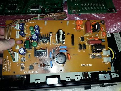
KK2494V-0 C22 C30 C23 C24 C19 C18 C16 C5 C9 C7 R1 D1 D2 D4 D5 D6 D7 T1 25A 250V C1 C2 C3 C13 C14 CN14 CN15 SW SW L1 TH1 TH2 R6 R7 R8 R9 R10 R13 R14 R15 R16 R17 R18 R19 R20 R21 R22 R23 R24 R25 R26 R27 R28 R29 R30 R31 R32 R33 R34 R35 R36 R37 R38 R39 R40 R41 R42 R43 R44 R45 R46
in
„Benötige Hilfe bei Reparatur: Schaltnetzteil von Korg T3 Keyboard“
·
Analoge Elektronik und Schaltungstechnik
·
02.09.2024 18:05
·
Platinenfotos
Bild
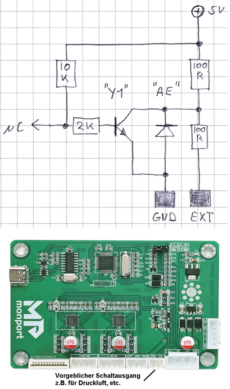
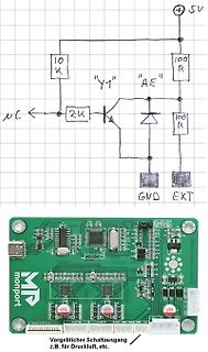
SV 10K Y1 AE 100R 2K NC 100R GND EXT monport Y-Motor X-Motor L1 L2 L3 L4 L5 L6 L7 L8 L9 L10 L11 L12 L13 L14 L15 L16 L17 L18 L19 L20 L21 L22 L23 L24 L25 L26 L27 L28 L29 L30 L31 L32 L33 L34 L35 L36 L37 L38 L39 L40
in
„Enträtselung einer Schaltung (Laser)“
·
Analoge Elektronik und Schaltungstechnik
·
09.03.2024 21:17
·
Fotos
Bild
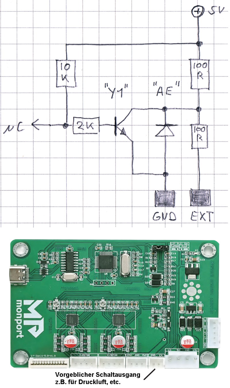
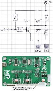
SV 10K "Y1" "AE " 100 R 2K NC 100 R GND EXT monport Y-Motor X-Motor L1 L2 L3 L4 L5 L6 L7 L8 L9 L10 L11 L12 L13 L14 L15 L16 L17 L18 L19 L20 L21 L22 L23 L24 L25 L26 L27 L28 L29 L30 L31 L32 L33 L34 L35 L36 L37 L38 L39 L40
in
„Enträtselung einer Schaltung (Laser)“
·
Analoge Elektronik und Schaltungstechnik
·
09.03.2024 21:21
·
Fotos
Bild
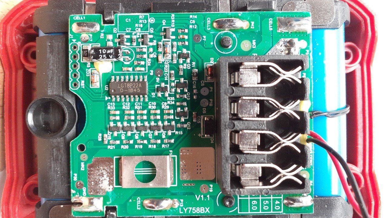
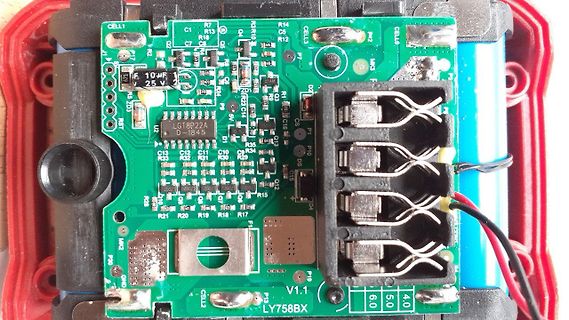
R13 R14 R15 R16 R17 R18 R19 R20 R21 R22 R23 R24 R25 R26 R27 R28 R29 R30 R31 R32 R33 R34 R35 LGT8P22A D-184.5 10uF 25V P8 P9 P10 P11 P12 P13 P14 P15 P16 P17 P18 P19 P20 P21 P22 P23 P24 P25 P26 P27 P28 P29 P30 P31 P32 P33 P34 P35 P36 P37 P38 P39 P40 P41 P42 P43 P44 P45 P46 P47 P48 P49 P50 P51 P52 P53
in
„Li-Ion ohne Balancer in Werkzeugen?“
·
Mechanik, Gehäuse, Werkzeug
·
14.05.2025 14:33
·
Platinenfotos
Bild
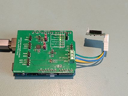
EVSE Emulator V1.0 https://github.com/SebIR SDA Gnd Digital I/O Digital I/O SCL ARef 13 12 10 9 Idle A Boost EN GND IC2 R3 R4 R5 R6 R7 R8 R9 R10 R11 R12 R13 R14 R15 R16 R17 R18 R19 R20 R21 R22 R23 R24 R25 R26 R27 R28 R29 R30 R31 R32 R33 R34 R35 R36 R37 R38 R39 R40 R41 R42 R43 R44 R45 R46 R47 R48 R49 R50
in
„"EVmulator" - Ladesäule auf Schuko mit Kfz-Emulation“
·
Projekte & Code
·
04.06.2025 09:45
·
Platinenfotos
Bild
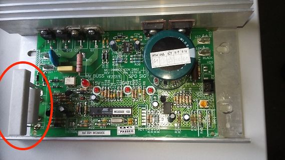
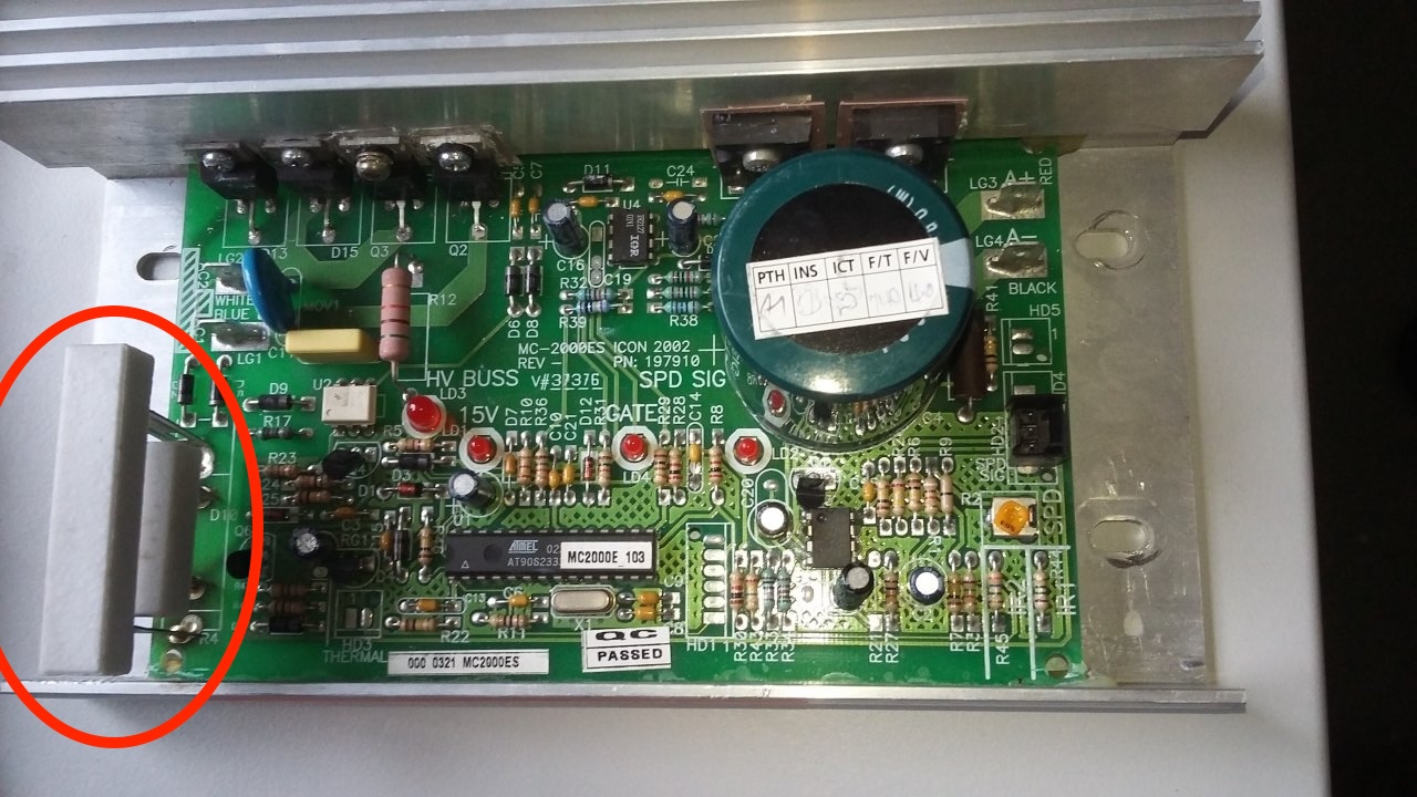
LG3 RED WHITE BLUE LG4A BLACK HD5 HD1 LG1 LG2 LG3 D15 D3 Q2 C24 U4 C16 R3 C19 R38 R4 R12 MC-2000ES ICON 2002 PN: 197910 HV BUSS V#239E SPD SIG LD3 15V R5 R6 R7 R8 R9 R10 R11 R12 R13 R14 R15 R16 R17 R18 R19 R20 R21 R22 R23 R24
in
„Suche einen AT90(L)S2333 DIL28 uC“
·
Markt
·
07.04.2025 16:16
·
Platinenfotos
109 ≥ 109 Ω *Refer to the front of the optocoupler section of the current catalog, under Product Safety Regulations section IEC/EN/DIN EN 60747-5-2, for a detailed description. Note: Isolation characteristics
in
„Logic Gate Optocoupler“
·
Mikrocontroller und Digitale Elektronik
·
12.10.2006 03:18
OE2A Y3 PIU1011 PIU2042B E E A OE2B Y5 PIU1010 PIU206 GND A P +5 A Y6 PIU109 PIU205 RSTST GND U3U3 +5 PIU108 GND Y7 PIU107 LCD6 MC74HC00AD I3P233501P 42U1P 40 U4U4 U5OU5 PIU302CE VCC PIU3028 P80C31X2BA PIU501GND PSENENPIU302OE VPP PIU301 M74HC238B1R E N P T 2 1 C GND A S V R A A V P0.0/AD0PIU4043 D0PIU509D8 Q8 PIU5012 AL0 PIU301A 0 Q0 PIU3011 U6U +5 PIU401NIC P A X X P0.1/AD1PIU4042 D1PIU508D7 Q7 PIU5013 NLAL2 PIU309A 1 Q1 PIU3012 PIU603 CLK VCC PIU6016 PIU401NIC E P0.2
in
„Frage zum 80C31“
·
Mikrocontroller und Digitale Elektronik
·
25.01.2013 10:45
* requires a hard reset. This test restarts with any M104/M109 /M303, but only * if the current temperature is far enough below the target for a reliable * test. * * If you get false positives for "Heating failed"
in
„Marlin 2.0.72 lässt sich nicht compilieren“
·
Mikrocontroller und Digitale Elektronik
·
04.11.2020 17:10
l a : c a e - M E 4 PRODUCT SPECIFICATION KPS-0293-A 04 5 Module Interface PIN NO. PIN NAME DESCRIPTION This pin is the power output pin of internal row power regulator. A 4.7uF capacitor is 1 VCC_R recommended
in
„DCDC Wandler Berechnungsproblem“
·
Analoge Elektronik und Schaltungstechnik
·
08.07.2013 08:50
IRLML6401 Vbat = 1,56V-2,93V (bei +12V = 8V - 15V) schwarz Vbat K108 vio T101 +12V R404 R405 R406 6 K109 braun D101 +4V 2 F 3 +/ K110 C101 R105 5k6 1k8 1k8 T401 6 n 6 µ T100 SH_ON/OFF D403 C 1 C 0 1K +12V IC400 +4V_SW 1 BCW66 100nF IRLML6401 IC600 R106 a OE GND Lüften/Heizen i uD d / P6KE6V8CA C408 I/O
in
„Bitte um Überprüfung: GSM Steuerung mit GPS“
·
Mikrocontroller und Digitale Elektronik
·
26.10.2011 17:24
TV_KEY_BLUE 0x7300 #define TV_KEY_INFO 0x3900 #define TV_KEY_EXIT 0xD300 #define TV_KEY_CUR_UP 0x4a 00 #define TV_KEY_CUR_DOWN 0x4b00 #define TV_KEY_CUR_LEFT 0x4e00 #define TV_KEY_CUR_RIGHT 0x4f00 #define TV_KEY_OK 0x4900 #define TV_KEY_OPTION 0xa709 #define TV_KEY_RETURN 0xd400 #define TV_KEY_APPS
in
„Decoding Panasonic IR-Remote“
·
Mikrocontroller und Digitale Elektronik
·
18.09.2021 10:31
for ( j = 51; 0<j; j-- ) { } } } void farbenwechsel120(){ uint8_t red=255, blue=0, green=0; //OCR1A =Green OCR1B=Red OCR2=Blue //1 if(red==255 && blue==0){ for(green=0; green<255; green++){ OCR1A = pgm_read_word(&pwmtable_16[green]); delay_ms(100); } } //2 if(green==255 && blue==0){ for(red=255; red
in
„Port als Ausgang gesetzt geht direkt auf High. Wieso?“
·
Mikrocontroller und Digitale Elektronik
·
02.06.2012 12:37
FROM SID CLR SCLK CLR SCLK MOVBIT SID, A .6; SID = A .6 MOVBIT SID, A .5 ; SID = A .5 SETB SCLK ; READ DATA FROM SID SETB SCLK ; READ DATA FROM SID CLR SCLK CLR SCLK MOVBIT SID, A .5; SID = A .5 MOVBIT SID, A .4 ; SID = A .4 SETB SCLK ; READ DATA FROM
in
„DDRAM Adressierung (DG-14032 GLCD)“
·
Mikrocontroller und Digitale Elektronik
·
24.06.2012 09:01

 Bild
 Bild
 Bild
 Bild
 Bild
 Bild
 Bild
 Bild
 Bild
 Bild
 Bild
 Bild
 Bild
 Bild