-
PDF
assembler_beginner.pdf
durch eine Folge von Instruktionen die ent- sprechende einschläfernde Wirkung programmieren, für den ATmega8 also z.B. so: ... .DEF MeinLieblingsregister = R16 LDI MeinLieblingsregister, 0b10000000 OUT MCUCR, MeinLieblingsregister SLEEP Die Out-Instruktion bringt den Inhalt meines Lieblingsregisters, nämlich
in „Assembler Tutorial als PDF ?“ · Mikrocontroller und Digitale Elektronik ·
-
Datei
dude511.txt
unknown) avrdude: Recv: q [71] Device code: 0x71 = (unknown) avrdude: Recv: r [72] Device code: 0x72 = ATMEGA32 avrdude: Recv: s [73] Device code: 0x73 = (unknown) avrdude: Recv: t [74] Device code: 0x74 = ATMEGA6450 avrdude: Recv: u [75] Device code: 0x75 = ATMEGA6490 avrdude: Recv: v [76] Device code: 0x76 = ATMEGA8 avrdude: Recv: w [77] Device code: 0x77 = (unknown) avrdude: Recv: x [78] Device code: 0x78 = ATMEGA169 avrdude: Recv: y [79] Device code: 0x79 = (unknown) avrdude: Recv: z [7a] Device code: 0x7a
in „avrdude - Probleme unter Mac OS X 10.7 (Lion)“ · Mikrocontroller und Digitale Elektronik ·
-
Datei
dude511_mit_arduino_conf.txt
unknown) avrdude: Recv: q [71] Device code: 0x71 = (unknown) avrdude: Recv: r [72] Device code: 0x72 = ATMEGA32 avrdude: Recv: s [73] Device code: 0x73 = (unknown) avrdude: Recv: t [74] Device code: 0x74 = ATMEGA6450 avrdude: Recv: u [75] Device code: 0x75 = ATMEGA6490 avrdude: Recv: v [76] Device code: 0x76 = ATMEGA8 avrdude: Recv: w [77] Device code: 0x77 = (unknown) avrdude: Recv: x [78] Device code: 0x78 = ATMEGA169 avrdude: Recv: y [79] Device code: 0x79 = (unknown) avrdude: Recv: z [7a] Device code: 0x7a
in „avrdude - Probleme unter Mac OS X 10.7 (Lion)“ · Mikrocontroller und Digitale Elektronik ·
-
PDF
Powermeter.pdf
EP pulse width, EPH, by OCR1B. Extended Mode T/C When the calculated energy pulse interval exceeds 16 bits the firmware extended, 16- bit counter (TC1ext) is activated. The firmware counter value is increased each time the hardware counter reaches 16-bit maximum, effectively making the extended counter
in „230V Leistung erfassen mit ATmega128“ · Mikrocontroller und Digitale Elektronik ·
-
PDF
volt230.pdf
EP pulse width, EPH, by OCR1B. Extended Mode T/C When the calculated energy pulse interval exceeds 16 bits the firmware extended, 16- bit counter (TC1ext) is activated. The firmware counter value is increased each time the hardware counter reaches 16-bit maximum, effectively making the extended counter
in „Netzteil ohne Trafo“ · Mikrocontroller und Digitale Elektronik ·
-
PDF
energymeter.pdf
EP pulse width, EPH, by OCR1B. Extended Mode T/C When the calculated energy pulse interval exceeds 16 bits the firmware extended, 16- bit counter (TC1ext) is activated. The firmware counter value is increased each time the hardware counter reaches 16-bit maximum, effectively making the extended counter
in „Leistungsmessung über Shunt?“ · Analoge Elektronik und Schaltungstechnik ·
-
PDF
doc2566.pdf
EP pulse width, EPH, by OCR1B. Extended Mode T/C When the calculated energy pulse interval exceeds 16 bits the firmware extended, 16- bit counter (TC1ext) is activated. The firmware counter value is increased each time the hardware counter reaches 16-bit maximum, effectively making the extended counter
in „Cadsoft Eagle“ · Platinen ·
-
Datei
TimerOne.h
/* * Interrupt and PWM utilities for 16 bit Timer1 on ATmega168/328 * Original code by Jesse Tane for http://labs.ideo.com August 2008 * Modified March 2009 by Jérôme Despatis and Jesse Tane for ATmega328 support * Modified June 2009 by Michael
in „Rotary Encoder macht immer 4 Schritte“ · Mikrocontroller und Digitale Elektronik ·
-
Datei
mmc.h
nicht benutzt! also da nich die karte anschließen, sondern an MMC_Chip_Select ! #if defined (__AVR_ATmega128__) #define SPI_MISO 3 //Port Pin an dem Data Output der MMC/SD-Karte angeschlossen ist (DO) #define SPI_MOSI 2 //Port Pin an dem Data Input der MMC/SD-Karte angeschlossen ist (DI) #define SPI_Clock
in „VS1011 Register auslesen!“ · Mikrocontroller und Digitale Elektronik ·
-
Datei
build_failed.txt
funsigned-char -funsigned-bitfields -O0 -fpack-struct -fshort-enums -g2 -Wall -c -std=gnu99 -mmcu=atmega32 -MD -MP -MF"GLCD_KS0108.d" -MT"GLCD_KS0108.d" -o"GLCD_KS0108.o" ".././GLCD_KS0108.c" .././GLCD_KS0108.c: In function 'main': C:\temp\GLCD_KS0108\GLCD_KS0108\GLCD_KS0108.c(28,2): pointer targets in
in „GLCD KS0108 und apetech lib aus dem Wiki“ · Mikrocontroller und Digitale Elektronik ·
-
Datei
Keyb.c
#define DDR(x) (*(&x - 1)) /* address of data direction register of port x */ #if defined(__AVR_ATmega64__) || defined(__AVR_ATmega128__) /* on ATmega64/128 PINF is on port 0x00 and not 0x60 */ #define PIN(x) ( &PORTF==&(x) ? _SFR_IO8(0x00) : (*(&x - 2)) ) #else #define PIN(x) (*(&x - 2)) /* address of input register of port x */ #endif #ifndef __PROGMEM unsigned char EE_KeyTable[16] EEMEM = {'A','B','C','D',\ '3','6','9','#',\ '2','5','8','0',\ '1','4','7','*' }; #else unsigned char KeyTable[16] PROGMEM = {'A','B','C','D',\ '3','6','9','#',\ '2','5','8','0',\ '1','4','7','*' };
in „Display Programmierung mit GCC 16x4 Display“ · Mikrocontroller und Digitale Elektronik ·
-
Datei
avr-gcc_8.5.0_relax_MegaCoreX_-v_-Wl-v.txt
Arduino: 1.8.19 (Windows 10), Board: "ATmega4809, Nano Every, EEPROM retained, Reset, BOD 2.6V, Internal 16 MHz, No bootloader" C:\Arduino IDE Portable\megaAVR0\arduino-1.8.19\arduino-builder -dump-prefs -logger=machine -hardware C:\Arduino IDE
in „GCC v14 Release“ · Mikrocontroller und Digitale Elektronik ·
-
Datei
RC5-ATmega32.asm
/* RC5-ATmega32 nach rc5.asm von ATMEL NORWAY Quarts 4MHz */ .INCLUDE "M32DEF.INC" .DEVICE ATmega32 .EQU INPUT = 2 //PD2 (INT0) Interrupt .EQU SYS_ADDR = 0 //System Adresse .DEF S = R0 //Storage for the Status Register
in „Bekomme AVR 410 nicht zum laufen“ · Mikrocontroller und Digitale Elektronik ·
-
Datei
RC5-ATmega32.asm
/* RC5-ATmega32 nach rc5.asm von ATMEL NORWAY Quarz 4MHz */ .INCLUDE "M32DEF.INC" .DEVICE ATmega32 .EQU INPUT = 2 //PD2 (INT0) Interrupt .EQU SYS_ADDR = 0 //System Adresse .DEF S = R0 //Storage for the Status Register
in „Bekomme AVR 410 nicht zum laufen“ · Mikrocontroller und Digitale Elektronik ·
-
Datei
RTTTL8.bas
Auswertungen verwendet werden 'Timer2 im CTC-Modus 'funktioniert mit kleinen Änderungen auch auf Atmega16/32/644 usw. 'funktioniert mit kleinen Änderungen auch auf ATINY45 '------------------------------------------------------------------------------------- $regfile = "m8def.dat" 'ATmega8-Deklarationen
in „RTTTL-Klingeltoninterpreter für Atmega8 in BASCOM“ · Projekte & Code ·
-
Datei
RTTTL8_2.bas
Auswertungen verwendet werden 'Timer2 im CTC-Modus 'funktioniert mit kleinen Änderungen auch auf Atmega16/32/644 usw. 'funktioniert mit kleinen Änderungen auch auf ATINY45 '------------------------------------------------------------------------------------- $regfile = "m8def.dat" 'ATmega8-Deklarationen
in „RTTTL-Klingeltoninterpreter für Atmega8 in BASCOM“ · Projekte & Code ·
-
Datei
bm30b.s
/../include ; -I ../include -I ../../../include -I /usr/include/simavr ; -imultilib avr5 -D__AVR_ATmega328P__ -D__AVR_DEVICE_NAME__=atmega328p ; -D F_OSC=12000000 -D F_CPU=12000000 ; /home/lmeier/Projekte/wmucpp/doc/bmcpp20/bm30b.cc -mn-flash=1 ; -mmcu=avr5 -auxbase-strip bm30b.s -Os -Wall -Wextra -std
in „Assembler (AVR) Freaks bitte: der schnellste Weg, einen ganzzahligen Wert zu skalieren?“ · Mikrocontroller und Digitale Elektronik ·
-
Datei
8_Kanal_Laufzeitmesser.c
verbinden //---------------------------------------------------------------------- // Prozessor : Atmega8 // Takt : 16.000 MHz externer Quartz // Sprache : C // Version : 1.0 // Datum : 26.07.2013 //---------------------------------------------------------------------- #include <avr\io.h> #include <util
in „Über einen µC Laufzeit messen und über RS232 ausgeben“ · Mikrocontroller und Digitale Elektronik ·
-
Datei
ohne_kontrollausgabe.asm
ldd r24, Z+26 ; 0x1a 164: 98 17 cp r25, r24 166: 31 f0 breq .+12 ; 0x174 <HardwareSerial::peek()+0x16> return -1; } else { return _rx_buffer[_rx_buffer_tail]; 168: 82 8d ldd r24, Z+26 ; 0x1a 16a: e8 0f add r30, r24 16c: f1 1d adc r31, r1 16e: 85 8d ldd r24, Z+29 ; 0x1d 170: 90 e0 ldi r25, 0x00 ; 0 172
in „AVR Inline Optimierung kaputt?“ · Mikrocontroller und Digitale Elektronik ·
-
PDF
_Dokumentation_V1.6_Stand_04.08.2012.pdf
für eine „Holzkiste“ die mit Holzzierleisten verschönert wurde. 4 Also fasse ich mal zusammen: µC ATMega@16MHz LED Blau 1000 Stück Programmiersprache BASCOM Unterbau Holzbox Zeitaufwand 1-2 Stunden nach der Arbeit Projektstart 25.09.2011 Hier nochmal die LED-Matrix: 5 Abgleich der Funktionsweise mit den
in „Tutorial 10x10x10 LED-Cube“ · Mikrocontroller und Digitale Elektronik ·
-
Datei
atmega32u2.patch
95,6 +95,7 @@ extern gdb_io_reg_def_type atmega3290p_io_registers[]; extern gdb_io_reg_def_type atmega329p_io_registers[]; extern gdb_io_reg_def_type atmega32hvb_io_registers[]; +extern gdb_io_reg_def_type atmega32u2_io_registers[]; extern gdb_io_reg_def_type atmega32u4_io_registers[]; extern gdb_io_reg_def_type atmega406_io_registers[]; extern gdb_io_reg_def_type atmega48p_io_registers[]; diff -Nur a/src/jtag2prog.cc b/src/jtag2prog.cc --- a/src/jtag2prog.cc
in „avarice und atmega32u2“ · Mikrocontroller und Digitale Elektronik ·
-
Datei
eeprom.c
1307, USA. *************************************************************************/ #if !__AVR_ATmega8__ #error "this module is only tested for ATmega 8!" #endif #include "f_cpu.h" /************************************************************************* * einbinden der System header *************
in „EEPROM schreiben ohne Unterbrechung“ · Mikrocontroller und Digitale Elektronik ·
-
Datei
avreth-netlist.txt
AVRETH1 winziger Webserver mit ENC28J60 und ATMEGA32 / ATMEGA644 avr.auctionant.de/avrETH1/ http://www.mikrocontroller.net/forum/read-1-310134.html http://www.mikrocontroller.net/forum/read-1-402627.html Conntections between ICs sorted by IC pins of
in „winziger Webserver mit enc28j60+mega32“ · Mikrocontroller und Digitale Elektronik ·
-
 Bild
Bild
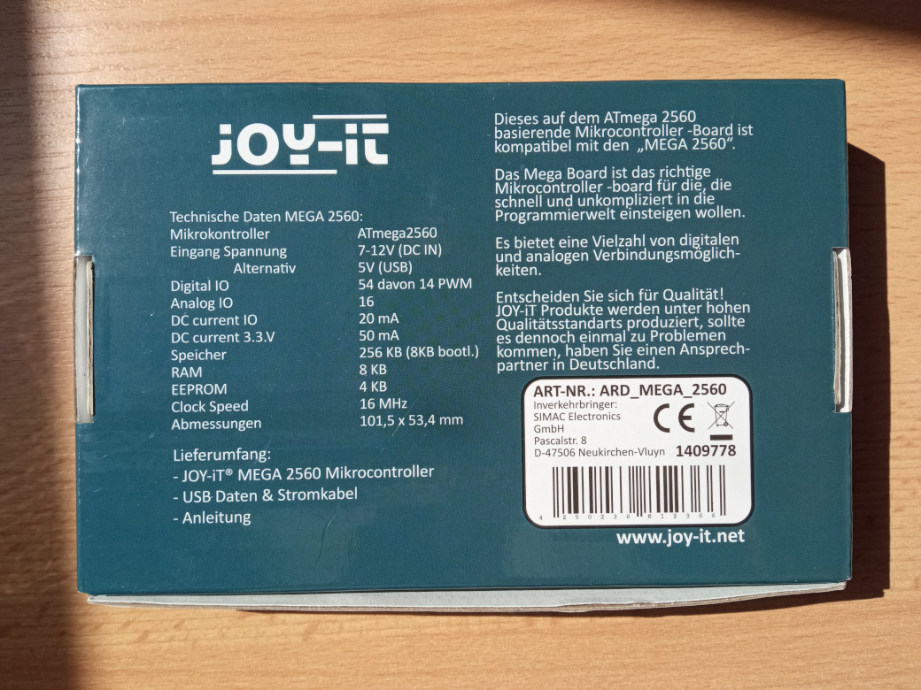
Rückseite einer JOY-IT Mega 2560 Verpackung
JOY-IT Dieses auf dem ATmega 2560 basierende Mikrocontroller-Board ist kompatibel mit den „MEGA 2560". Das Mega Board ist das richtige Mikrocontroller-board für die, die schnell und unkompliziert in die Programmierwelt einsteigen
in „[V] Joy-it ARD Mega2560R3, neu in OVP“ · Markt · · Fotos
-
Datei
SerialTest.txt
define UART_BAUD_RATE 9600 #define UART_BAUD_CALC(UART_BAUD_RATE,F_OSC) ((F_CPU)/((UART_BAUD_RATE)*16L)-1) int main(void) { int i; DDRB=0xff; /* USART-Init beim ATmegaXX */ UBRRH=(uint8_t)(UART_BAUD_CALC(UART_BAUD_RATE,F_CPU)>>8); UBRRL=(uint8_t)UART_BAUD_CALC(UART_BAUD_RATE,F_CPU); while (1) { PORTB
in „ATmega16 und UART“ · Mikrocontroller und Digitale Elektronik ·
-
Datei
usiTwiSlave.c
------------------------------------------- Change Activity: Date Description ------ ------------- 16 Mar 2007 Created. 27 Mar 2007 Added support for ATtiny261, 461 and 861. 26 Apr 2007 Fixed ACK of slave address on a read. 04 Jul 2007 Fixed USISIF in ATtiny45 def 12 Dev 2009 Added callback functions
in „Referenz von "usi_onReceiverPtr"“ · Mikrocontroller und Digitale Elektronik ·
-
PDF
beispiele.pdf
SIG_INTERRUPT0 External interrupt1 function name: SIG_INTERRUPT1 External interrupt2 function name (ATmega): SIG_INTERRUPT2 External interrupt3 function name (ATmega[16]03) SIG_INTERRUPT3 External interrupt4 function name (ATmega[16]03): SIG_INTERRUPT4 External interrupt5 function name (ATmega[16]03): SIG_INTERRUPT5 External interrupt6 function name (ATmega[16]03): SIG_INTERRUPT6 External interrupt7 function name (ATmega[16]03): SIG_INTERRUPT7 Output compare2 interrupt function name: SIG_OUTPUT_COMPARE2 Overflow2 interrupt function name: SIG_OVERFLOW2
in „Messwerte in EEProm speichern“ · Mikrocontroller und Digitale Elektronik ·
-
PDF
haraleit.pdf
SIG_INTERRUPT0 External interrupt1 function name: SIG_INTERRUPT1 External interrupt2 function name (ATmega): SIG_INTERRUPT2 External interrupt3 function name (ATmega[16]03) SIG_INTERRUPT3 External interrupt4 function name (ATmega[16]03): SIG_INTERRUPT4 External interrupt5 function name (ATmega[16]03): SIG_INTERRUPT5 External interrupt6 function name (ATmega[16]03): SIG_INTERRUPT6 External interrupt7 function name (ATmega[16]03): SIG_INTERRUPT7 Output compare2 interrupt function name: SIG_OUTPUT_COMPARE2 Overflow2 interrupt function name: SIG_OVERFLOW2
in „avr bibliothek“ · Mikrocontroller und Digitale Elektronik ·
-
Datei
FunksteckdoseQuigg.ino
to Arduino device. // // The 16 bit Timer1 is used @ 2MHz for geneating PWM pulses, but there is no need for 16 bit accurancy. // // 0 |-|___ 1 clk high, 3 clk low // 1 |---|_ 3 clk high, 1 clk low // S |-|_______ sync 1 clk high,
in „LIDL/BAT Funksteckdose Protokoll reverse-engineering“ · Mikrocontroller und Digitale Elektronik ·
-
Datei
Sample.c
////////// /* Initialisiert das SPI (Master-Mode) Außerhalb von Testfällen sind alle verwendeten ATmega im Master-Mode zu betreiben */ void SPI_init(); /* Initialisiert das Funkmodul Muss nach der SPI-Initialisierung geschehen, da zum Initialisieren das SPI benötigt wird */ void RFM12_init(); /* Initialisiert
-
Datei
uart.h
in bps, e.g. 1200, 2400, 9600 */ #define UART_BAUD_SELECT(baudRate,xtalCpu) ((xtalCpu)/((baudRate)*16l)-1) /** @brief UART Baudrate Expression for ATmega double speed mode * @param xtalcpu system clock in Mhz, e.g. 4000000L for 4Mhz * @param baudrate baudrate in bps, e.g. 1200, 2400, 9600 */ #define
in „Inkonsistentes Verhalten einfachem avr-gcc-codes“ · Mikrocontroller und Digitale Elektronik ·
-
Datei
RTC.c
the use of I2C RTC (Real Time Clock) (DS1307). Here the DS1307 RTC Module is connected with an AVR ATmega8 MCU by I2C Serial Bus. This program reads time from the DS1307 and displays it in 16x2 LCD Module. The system also has two buttons for user interaction. The 3 buttons are 1)MENU/Enter/Move selection
in „LCD zeigt nur die hälfte an“ · Mikrocontroller und Digitale Elektronik ·
-
Datei
Stopp-Uhr.asm
;************************************************************************** .include "m16def.inc" ;Definitionen für ATMega16 //rjmp main ;** ;** !!! Achtung bei ATMega 16 und LCD an PortC muß JTAG Bit aus sein ;** ;** //Für TimerOverflows ;** CPUTAKT = 4000000 ;** 1_byte = 256 ;** overfl
in „probleme mit stoppuhr programm“ · Mikrocontroller und Digitale Elektronik ·
-
Datei
serial.c
/* * FreeRTOS serial port driver for ATMega128 and AT90CAN128 * Supports UATS0 and UART1 of the MCU (at same time) * Fully interrupt driven. * Based on implementation for ATMega323 * Jonas Mitschang - jonen@mitschang.net */ #include <stdlib.h
in „(wieder mal) AT90CAN128 und USART“ · Mikrocontroller und Digitale Elektronik ·
-
PDF
Arduino-UNO-Rev3e-SCH.pdf
PB3 17 MISO2 T D 41 RESET (SCK)PB5 19 SS 3 10 P 9 22R RN3A p H 1 Y 2 XTAL2(PC0) (PDI/MOSI/PCINT2)PB2 16 MOSI2 D C S (MISO)PB4 18 2 9 8 P 1 XUSB 8 1 N 9 2 6 R1 (SCLK/PCINT1)PB1 15 SCK2 GND XTAL2 T (MOSI)PB3 17 1 8 P T D B 2 D- RD- G C 1 1M 1 XTAL1 (SS/PCINT0)PB0 14 R2 10 XTAL2 (SS)PB2 16 SS T D 2 1 3 D+
in „Arduino UNO an 4fach Relais“ · Mikrocontroller und Digitale Elektronik ·
-
PDF
Arduino-UNO-Rev3e-SCH.pdf
PB3 17 MISO2 T D 41 RESET (SCK)PB5 19 SS 3 10 P 9 22R RN3A p H 1 Y 2 XTAL2(PC0) (PDI/MOSI/PCINT2)PB2 16 MOSI2 D C S (MISO)PB4 18 2 9 8 P 1 XUSB 8 1 N 9 2 6 R1 (SCLK/PCINT1)PB1 15 SCK2 GND XTAL2 T (MOSI)PB3 17 1 8 P T D B 2 D- RD- G C 1 1M 1 XTAL1 (SS/PCINT0)PB0 14 R2 10 XTAL2 (SS)PB2 16 SS T D 2 1 3 D+
in „Arduino Ethernet Shield Sketches auf Arduino laden“ · Mikrocontroller und Digitale Elektronik ·
-
PDF
Arduino-UNO-Rev3e-SCH.pdf
PB3 17 MISO2 T D 41 RESET (SCK)PB5 19 SS 3 10 P 9 22R RN3A p H 1 Y 2 XTAL2(PC0) (PDI/MOSI/PCINT2)PB2 16 MOSI2 D C S (MISO)PB4 18 2 9 8 P 1 XUSB 8 1 N 9 2 6 R1 (SCLK/PCINT1)PB1 15 SCK2 GND XTAL2 T (MOSI)PB3 17 1 8 P T D B 2 D- RD- G C 1 1M 1 XTAL1 (SS/PCINT0)PB0 14 R2 10 XTAL2 (SS)PB2 16 SS T D 2 1 3 D+
in „Arduino 5V auf 3V regeln 40mA“ · Analoge Elektronik und Schaltungstechnik ·
-
Datei
avr8_servos.c
uS*/ volatile uint8_t int_erfolgt = 0; struct _Servoliste_generell { uint8_t adr; uint8_t pin; uint16_t absmax; uint16_t absmin; } servo_gen[maxservos+1]; struct _Servo_rel { uint8_t ein; uint8_t pos; /* zum test von 16 auf 8*/ uint16_t max; uint16_t min; }volatile servo_rel[maxservos+1]; struct _Servo_abs
in „Servocontroller mit ATmega8 für 20 Servos“ · Projekte & Code ·
-
Datei
dcf77.c
/* * dcf77.c – DCF77-Empfaenger fuer ATmega32A, 16 MHz Quarz * * Signal : Port A, Bit 0 (PA0), interner Pull-Up aktiv * Timer : Timer1, CTC-Mode, 10 ms Takt (Prescaler 8, OCR1A = 19999) * UART : 9600 Baud (UBRR = 103) * Compiler : avr-gcc, -
in „Programmieren mit KI“ · Offtopic ·
-
Datei
dcf77_korrigiert.c
/* * dcf77.c – DCF77-Empfaenger fuer ATmega32A, 16 MHz Quarz * * Signal : Port A, Bit 0 (PA0), interner Pull-Up aktiv * Timer : Timer1, CTC-Mode, 10 ms Takt (Prescaler 8, OCR1A = 19999) * UART : 9600 Baud (UBRR = 103) * Compiler : avr-gcc, -
in „Programmieren mit KI“ · Offtopic ·
-
PDF
RC_Funk.pdf
Band empfangen und das auch noch selbst entscheiden. Bidirektional daher nicht möglich... • Zwei Atmega. Habe zwei Atmega32 genommen. Geht aber auch mit zwei 8ern. • Für die PC-Kommunikation einen Pegelwandler. • Kleinteile, wie Kabel und Batterien. 1.4. Ist so etwas zulässig? Das wüsste ich auch gerne
in „Datenversand über RC - Fernbedienungen“ · Projekte & Code ·
-
Datei
bootloader.py
self.readval() targets = { 0x1e9007: "ATtiny13", 0x1e910A: "ATtiny2313", 0x1e9206: "ATtiny45", 0x1e9205: "ATmega48", 0x1e9307: "ATmega8", 0x1e9403: "ATmega16", 0x1e9406: "ATmega168", 0x1e9502: "ATmega32", 0x1e9609: "ATmega644", 0x1e9802: "ATmega2561", 0x1e9404: "ATmega162", } print "Target: %06x %s" % (i, targets
in „UART Bootloader ATtiny13 - ATmega644“ · Projekte & Code ·
-
Datei
uart.asm
.include "m8def.inc" .device ATmega8 .def sek=R20 .def zeit=R21 .equ status=0x19 .cseg .org 0x000 jmp reset .org 0x009 jmp t_0_int .org 0x020 reset: ldi R16,low(RAMEND) out SPL,R16 ; Set stack pointer to last internal RAM location ldi R16,high(RAMEND) out SPH,R16 ldi R16,0x18 out WDTCR,R16 ldi R16,0x00 out WDTCR,R16 ; disable Watchdog sei ; global Int enable ldi R16,100 out TCNT0,R16 ; Timer 0 ldi R16,0x01 out TIMSK,R16 ; Timer 0 Interrupt
in „UART bei ATMega8“ · Mikrocontroller und Digitale Elektronik ·
-
 Bild
Bild
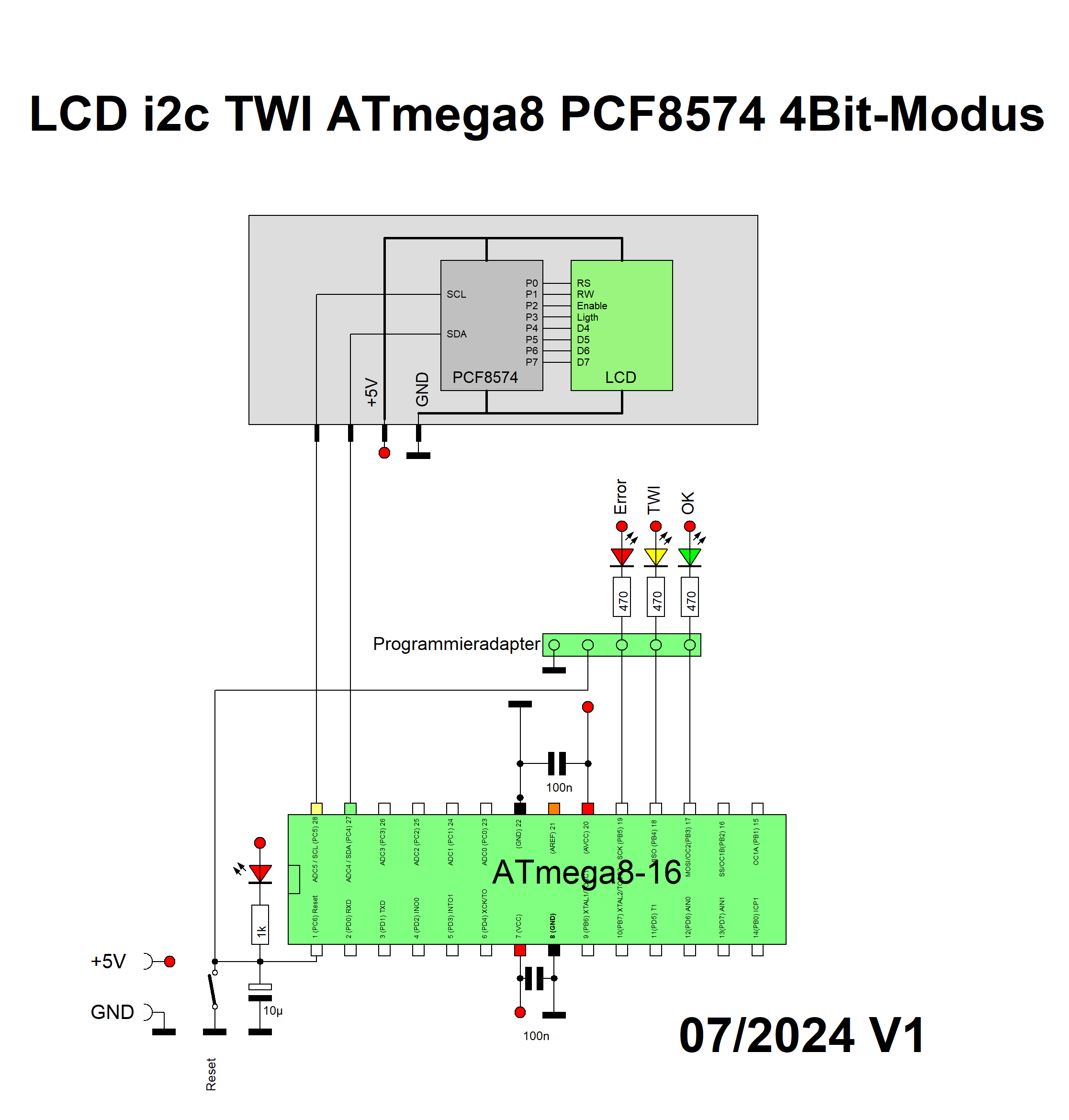
Schaltplan ATmega8 mit PCF8574 und LCD-Ansteuerung
LCD i2c TWI ATmega8 PCF8574 4Bit-Modus P0 RS P1 RW P2 Enable P3 Light P4 D4 P5 D5 P6 D6 P7 D7 SCL SDA +5V GND PCF8574 LCD Error TWI OK 470 470 470 Programmieradapter 100n AD0 A5 I2C SDA P25 AD1 A4 I2C SCL P24 AD2 A3 I2C P23 AD3 A2 I2C P22 AD4 A1 I2C P21 AD5 A0 I2C P20 GND P19 A6 I2C P18 P17 TWI SDA P16 TWI SCL P15 I2C P14 P13 P12 P11 P10 P9 P8 P7 P6 P5 P4 P3 P2 P1 P0 +5V GND 1k 10µ Reset 100n ATmega8-16 07/2024 V1
in „i2c TWI LCD 4Bit PCF8574 HD44780 ATmega8 Assembler“ · Projekte & Code · · Schaltpläne
-
Datei
PicoTerm-demo.ino
('f'); tft_int16(x1); tft_int16(y1); tft_int16(x2); tft_int16(y2); tft_ausgabe(col); } // Linie zwischen den Endpunkten void zeichne_linie(short x1,short y1, short x2, short y2, uint8_t col) { tft_command('g'); tft_ausgabe('l'); tft_int16(x1); tft_int16(y1); tft_int16(x2); tft_int16(y2); tft_ausgabe(col); } // einzelner Punkt void tft_dot(short x1,short y1, uint8_t col) { tft_command('G'); tft_ausgabe('p'); tft_int16(x1); tft_int16(y1
in „PicoTerm-TFT, farbiges 4,3"-Terminal mit Pico-Board RP2040“ · Projekte & Code ·
-
Datei
Vergleich.txt
ATmega16 ATmega32 Soll F.B.-Ist nix: 949000 1 RESET 947300 RESET 947300 okay 2 INT0 nix INT0 nix okay 3 INT1 nix INT1 nix okay 4 TIMER2 COMP nix INT2 nix okay 5 TIMER2 OVF nix TIMER2 COMP nix okay 6 TIMER1
in „Hex File von Atmega16 in Atmega32 verwandeln“ · Mikrocontroller und Digitale Elektronik ·
-
Datei
m48def.inc
I L Y ;* ;* Number :AVR000 ;* File Name :"m48def.inc" ;* Title :Register/Bit Definitions for the ATmega48 ;* Date :13.08.03 ;* Version :1.00 ;* Support E-mail :support@atmel.no ;* Target MCU :ATmega48 ;* ;* DESCRIPTION ;* When including this file in the assembly program file, all I/O register ;* names
in „.def.inc-Datei für AtMega48“ · Mikrocontroller und Digitale Elektronik ·
-
Datei
Freqgen-M8-Ver3.0_08-01-2012.bas
'( Rechteck Frequenzgenerator mit Atmega8 Von 0 , 12 Hz Bis 8 Mhz(mit 16 Mhz Resonator / Quarz) Arne Groh 2009 -10 -08 Fuses: Default: 1101 1001 1110 0001(1 Mhz Intern) Here: 1100 1001 1110 1111(ext. Resonator) Mit Den Beiden Tasten Kann
in „Einstellbarer Frequenzgenerator für 0.12 Hz - 8 MHz mit Atmega 8 und Bascom“ · Projekte & Code ·
-
Datei
PWM16_ini.asm
; ; 16Bit PWM Timer1 ATmega8 ; Bernhard.Erfurt@gmx.de ; 22.02.2013 ; ; ; Anschlussbelegung PINS ; ; PB0 ==> ; PB1 ==> ; PB2 ==> ; PB3 ==> ; PB4 ==> ; PB5 ==> ; PB6 ==> Quarz ; PB7 ==> Quarz ; ; PC0 ==> ; PC1
-
Datei
STM32F7_discovery_clock.ino
loaded by editting the User_Setup.h file in the TFT_ILI9341 library folder. If using an UNO or Mega (ATmega328 or ATmega2560 processor) then for best performance use the F_AS_T option found in the User_Setup.h file in the TFT_ILI9341 library folder. The pins used for the TFT chip select (CS) and Data/command
in „STM32F746 Discovery ARDUINO“ · Mikrocontroller und Digitale Elektronik ·