-
PDF
LinMon_Kurzanleitung_140.pdf
U , basierend auf dem ISO9141-Standard. batt Abb. 6-7 : Prinzipschaltbild Abb. 6-8 : Sende- bzw Empfangstoleranzen Sendeseitig wird eine Spannung von mindestens 80% U als „high“ definiert, ein batt Wert unter 20% von U battilt als „low“. Empfangseitig ist > 60% von Ubatt „high“, <
in „LIN Kommunikation Master Slave“ · Mikrocontroller und Digitale Elektronik ·
-
Datei
main.c
Enthält das zu schreibende Byte. * @retval None */ void SPI_WriteByte(unsigned char Byte) { SPI_I2S_SendData(SPI1, Byte); while(SPI_I2S_GetFlagStatus(SPI1, SPI_I2S_FLAG_TXE) == RESET); } /** * @brief Schreibt ein Byte an die Angegebene Adresse über den SPI Bus. * @param Addr: Enthält die Adresse an
in „STM32 SPI-Bus Probleme mit Prescaler und delay() Realisierung“ · Mikrocontroller und Digitale Elektronik ·
-
PDF
27920-Humidity-Sensor-Datasheet.pdf
T E C H N IC A L 1 A T A R E L A T IV EH U M ID IT YS E N S O R H S1 1 0 0/H S1 1 0 1 Based on a unique capacitive cell, these relative humidity sensors are designed for high 1 volume, cost sensitive applications such as office automation, automotive cabin air
in „Sensor anschließen ?“ · Mikrocontroller und Digitale Elektronik ·
-
PDF
TDA-884.pdf
A E C I + V S L P E B D F S 4 U 3 R 4 H 6 V 4 1 . C R 3 Y E P E N E T M D 5 M 9 S O L N R / C O 3 O 3 C t F U L E E N Y 1 T P S D 3 O S + E 3 Y/ SBVC Ò 4 s W 1 r hC C P S 0 M E A R S C 1 A S IV L T A Y H I R A 8 B
in „PAL-Röhren TV auf NTSC umbauen“ · Analoge Elektronik und Schaltungstechnik ·
-
Datei
LPH8731-3C.h
same for A75, C65, A60, C60, MC60, S55 acknowledgements: user neonix on RadioKat Forum Igor Kizim aka Igoryosha (ATMega, STM32 implementations) Dmitry Karech (MSP430 implementation) license: GPL v2 This program is free software; you can
in „LCD LPH8731-3C aus Siemens-Handys, Treiber“ · Mikrocontroller und Digitale Elektronik ·
-
Datei
config.c
/* Portbelegungen und Konfiguration: */ #include "StdTypes.h" #include "STM32F103all.h" #include "startup.h" #include "config.h" /* Portbelegungen und Konfiguration: ================================= Diese Konfiguration ist für den STM32F103C8T6, also im LQFP-48 Gehäuse. Zu
in „MINOS - Minos Is No Operating System“ · Projekte & Code ·
-
Datei
config.c
/* Portbelegungen und Konfiguration: */ #include "StdTypes.h" #include "STM32F103all.h" #include "startup.h" #include "config.h" /* Portbelegungen und Konfiguration: ================================= Diese Konfiguration ist für den STM32F103C8T6, also im LQFP-48 Gehäuse. Zu
in „Problem mit Clock Configuration beim STM32G031“ · Mikrocontroller und Digitale Elektronik ·
-
Datei
Zentrale.txt
funktioniert (2 nachrichten) ! 2.2 Nachrichtenstrukturt in eine pro Modul geändert 2.3 Modul 5, 6 und 8 eingepflegt Funktioniert! 2.4 Sendeintervall auf 500 mS gelegt und nachricht zu Modul 9 erstellt - Funktioniert 2.5 Nachricht an Modul 10 implementiert --- funktioniert -- -- Nachrichten Empfangen und
in „Arduino Blue Pill CAN bibliothek“ · Mikrocontroller und Digitale Elektronik ·
-
Datei
main.c
#include "stm32f4xx_conf.h" #define MAX_BUFFER_LENGTH 12 //Maximale Receive-Buffer-Länge volatile char received_string[MAX_BUFFER_LENGTH - 1]; //Receive-String-Buffer void Delay(__IO uint32_t nCount) { while(nCount
in „ARM Einstieg - Wie weitermachen?“ · Mikrocontroller und Digitale Elektronik ·
-
Datei
main.c
Hardware */ USART_Cmd(USART1, ENABLE); } /* * Sendet einen String an USART1 * * Argumente: volatile char *s --> Der zu sendene String */ void UART1_puts(volatile char *s){ while(*s){ while (USART_GetFlagStatus(USART1, USART_FLAG_TXE) == RESET); //Warten bis das Daten-Register leer ist USART_SendData(USART1, *s); *s++; } } int main(void){ SystemInit(); init_USART1(115200); Delay(1000000); UART1_puts("HALLO WELT! Es funktioniert!!!\n\r"); USART_DeInit(USART1); while(1){ } }
in „ARM Einstieg - Wie weitermachen?“ · Mikrocontroller und Digitale Elektronik ·
-
Datei
src.txt
quot;}" data-remote="true" rel="nofollow" href="/topic/delete_post/7363565?token=McsungP9lHPvu4Ude7sCGV7Zu3M%2Bw8Xsh5nDOK1OiLtAng%2BCmOpGrHW2ni4qu%2BO%2BhbLliSTQ9c6H3UaydCMoRw%3D%3D">Löschen</a></span> <span class="menuitem"><a href="?reply_to=7363565#postform" onclick="return !forumInsertQuoting(7363565
in „Verweis/Referenzierung zu anderen Beiträgen“ · www.mikrocontroller.net ·
-
Datei
main.c
(&htim1, &sBreakDeadTimeConfig) != HAL_OK) { Error_Handler(); } sConfigOC.OCMode = TIM_OCMODE_TIMING; sConfigOC.Pulse = 0; sConfigOC.OCPolarity = TIM_OCPOLARITY_HIGH; sConfigOC.OCNPolarity = TIM_OCNPOLARITY_HIGH
in „STM32 HAL Interrupt Callbacks in main.c implementieren?“ · Mikrocontroller und Digitale Elektronik ·
-
PDF
bmpm_v2_1c_schematic.pdf
1 2 3 4 5 6 7 8 POWER REG TARGET FRONTEND PWR_FLAG TPWR 1 +5V +3V3 n +3V3 +3V3 RST 1 P11 0 1 P12 VREG_3V3 1 C U4 2 TDI 1 P13 s 1 IN OUT 5 1 VCCA VCCB 8 xTPWR TDO 1 a 4 2 7 0 1 TCK 1 P14 P BYP 1A 1B 1 R 1 6 P15 i A 3
in „MOSFET Ersatztypen für DMG1024 u. DMG1023 gesucht“ · Analoge Elektronik und Schaltungstechnik ·
-
Datei
main.c
(); } sConfigOC.OCMode = TIM_OCMODE_PWM1; sConfigOC.Pulse = 0; sConfigOC.OCPolarity = TIM_OCPOLARITY_HIGH; sConfigOC.OCFastMode = TIM_OCFAST_DISABLE; if (HAL_TIM_PWM_ConfigChannel(&htim2, &sConfigOC, TIM_CHANNEL
in „STM32 SPI zu viele Clocks“ · Mikrocontroller und Digitale Elektronik ·
-
Datei
mmc_config.h
"uputs(uint8_t *s)" ist typedef void(*fptr_t)(uint8_t* arg); // in main.c definiert. konvertiert einen long zu string, wird nur von ls benoetigt #if (MMC_LS == TRUE) extern char *ltostr(long num, char *string, uint16
in „MMC SD library FAT16 FAT32 read write“ · Projekte & Code ·
-
Datei
mmc_config.h
"uputs(uint8_t *s)" ist typedef void(*fptr_t)(uint8_t* arg); // in main.c definiert. konvertiert einen long zu string, wird nur von ls benoetigt #if (MMC_LS == TRUE) extern char *ltostr(long num, char *string, uint16
in „AVR und großer Speicher“ · Mikrocontroller und Digitale Elektronik ·
-
Datei
main.c
TIM_AUTORELOAD_PRELOAD_DISABLE; if (HAL_TIM_Base_Init(&htim2) != HAL_OK) { _Error_Handler(__FILE__, __LINE__); } sClockSourceConfig.ClockSource = TIM_CLOCKSOURCE_INTERNAL; if (HAL_TIM_ConfigClockSource(&htim2, &sClockSourceConfig) != HAL_OK) { _Error_Handler(__FILE__, __LINE__); } sMasterConfig.MasterOutputTrigger
in „I2C Verbindung RPi - ST.Nucleo“ · Mikrocontroller und Digitale Elektronik ·
-
Datei
main.c
for the selected ADC regular channel its corresponding rank in the sequencer and its sample time. */ sConfig.Channel = ADC_CHANNEL_8; sConfig.Rank = ADC_REGULAR_RANK_1; sConfig.SamplingTime = ADC_SAMPLETIME_3CYCLES; if (HAL_ADC_ConfigChannel(&hadc3, &sConfig) != HAL_OK) { _Error_Handler(__FILE__, __LINE
in „32F746Disco, SW4STM32, kompiliert, nach kleiner Änderung aber nicht.“ · Mikrocontroller und Digitale Elektronik ·
-
Datei
sdcard.c
Write data to be transmitted to the SPI data register SPI2->DR = data; while (!(SPI2->SR & (SPI_I2S_FLAG_TXE))); /* Wait until transmit complete */ while (!(SPI2->SR & (SPI_I2S_FLAG_RXNE))); /* Wait until receive complete */ while (SPI2->SR & (SPI_I2S_FLAG_BSY)); /* Wait until SPI is not busy anymore
in „Problem FatFS + SPI“ · Mikrocontroller und Digitale Elektronik ·
-
Datei
schaltplan.txt
| +----|---| 4 NRST STM32F030F4P6 - TSSOP20 PF0 2 |----+ | | | | | | | | | | | | | | +---| 1 Boot0 | | | | | 7 8 | | | | | | | | +---------------------+ | | | GND PA0 PA1 PA2 PA3 PA4 PA5 PA6 PA7 PB1 PA13 PA14 PF1 | | | | 100n
-
Datei
myfirst.lst
ARM GAS myfirst.s page 1 1 0000 00000000 .org 0x400 1 00000000 1 00000000 1 00000000 1 00000000 2 .global Reset 3 .syntax unified 4 .cpu cortex-m4 5 .thumb 6 7 .equ BIT0, 0x00000001 8 .equ BIT1, 0x00000002 9 .equ BIT2
in „mein erstes STM32F4 .asm/ .s Program stürzt ab im gdb“ · Mikrocontroller und Digitale Elektronik ·
-
PDF
LIS302DL.pdf
Application hints Figure 5. LIS302DL electrical connection Vdd Vdd_IO 1 Z 6 1 Y X 13 10uF 6 Top VIEW 8 100nF 8 13 TOP VIEW DIRECTIONS OF THE DETECTABLE O ACCELERATIONS / D C 1 2 O / / C N N D D L I I S S S GND Digital signal from/to signal controller.Signal’s levels are defined by proper selection of
in „Verwirrung mit LIS302“ · Mikrocontroller und Digitale Elektronik ·
-
PDF
PWM_Dimming_Drive_Control_Board_For__High_Power_LEDs.pdf
1 2 3 4 5 6 7 8 0 0 P 2 S D1 0 0 0 2 SS210 F D P CS1 D P P 0 P CF1 CD6 U1 C 0.1uF 0 0 P0U108 P 100V L1 22uH C 22uF/10V C 470uF/10V 7 P0U107 8 P0L101 P0L102 P P A BST SW +5V A 1.5A 6 P0U106 +48V P1 GND P0U101 2 0 0 R1
in „RGB LED Interface ESP8266-01“ · Mikrocontroller und Digitale Elektronik ·
-
Datei
readme.txt
einen Easy-PDK-Programmer Clone hatte ich bereits aufgebaut, aber eben wie der originale mit einem STM32F072 der momentan nur relativ teuer erhältlich ist – Stand 12.12.2020). Google-Ergebnisse geben da derzeit nur 2 Projekte aus, die nicht auf dem oben genannten Programmer basieren. Beide habe ich ausprobiert
in „Padauk PFS154 Programmer mit Arduino Uno / ATmega88 - 328“ · Projekte & Code ·
-
Datei
readme.txt
einen Easy-PDK-Programmer Clone hatte ich bereits aufgebaut, aber eben wie der originale mit einem STM32F072. Dieser ist derzeit nur relativ teuer erhaetlich – Stand 12.12.2020). Google-Ergebnisse geben da derzeit nur 2 Projekte aus, die nicht auf dem oben genannten Programmer basieren. Beide habe
in „Padauk PFS154 Programmer mit Arduino Uno / ATmega88 - 328“ · Projekte & Code ·
-
Datei
oneWire.c
***/ /* Includes **********************************************************************/ #include "stm32f10x_conf.h" #include "Delay.h" #include "oneWire.h" #include "math.h" /* Functions **********************************************************************/ //reset device uint8_t ds1820_reset(GPIO_TypeDef
in „Timingproblem mit Onewire und STM32“ · Mikrocontroller und Digitale Elektronik ·
-
Datei
main.c
retval None */ void HAL_UART_RxCpltCallback(UART_HandleTypeDef *huart) { /* Prevent unused argument(s) compilation warning */ UNUSED(huart); volatile uint8_t test = 5; test++; /* NOTE : This function should not be modified, when the callback is needed, the HAL_UART_RxCpltCallback can be implemented in
in „STM32F0 HardFault bei UART Empfang“ · Mikrocontroller und Digitale Elektronik ·
-
Datei
usbd_storage_if.c
{ */ /* USER CODE BEGIN INQUIRY_DATA_FS */ /** USB Mass storage Standard Inquiry Data. */ const int8_t STORAGE_Inquirydata_FS[] = {/* 36 */ /* LUN 0 */ 0x00, 0x80, 0x02, 0x02, (STANDARD_INQUIRY_DATA_LEN - 5), 0x00, 0x00, 0x00, 'S', 'T', 'M', ' ', ' ', ' ', ' ', ' ', /* Manufacturer : 8 bytes */ 'P',
in „ARM [STM32] microSD SPI USB Massenspeicher“ · Mikrocontroller und Digitale Elektronik ·
-
Datei
isrhdl.c
*** */ #include "isrhdl.h" /* -------------- System Include Files ------------------- */ #include "stm32f10x_conf.h" /* -------------- Standard Include Files ----------------- */ #include <stdbool.h> #include <stdint.h> #include <stdio.h> /* -------------- Projekt Include Files ---------------- */ #include
in „Timer Interrupt STM32F103“ · Mikrocontroller und Digitale Elektronik ·
-
PDF
Core429I-Schematic.pdf
_RX/DCMI_D1/TIM3_CH2 PF7<>TIM11_CH1/FSMC_NREG/ADC3_IN5 20pF PC8 117 26 PF8 XTAL.C2 PC9 118 PC8<>TIM8_CH3/SDIO_D0/TIM3_CH3/USART6_CK/DCMI_D2 PF8<>TIM13_CH1/FSMC_NIOWR/ADC3_IN6 27 PF9 PC10 139 PC9<>I2S2_CKIN/I2S3_CKIN/MCO2/TIM8_CH4/SDIO_D1/I2C3_SDA/DCMI_D3/TIM3_CH4
in „STM32F4x9 - FMC - SSD196x“ · Mikrocontroller und Digitale Elektronik ·
-
Datei
gpio_ver2.h
#include "stm8s.h" void init_gpio(void);
in „sdcc source code in mehrere Dateien aufteilen“ · Mikrocontroller und Digitale Elektronik ·
-
Datei
stm32f4x7_eth.c
**** */ /* Includes ------------------------------------------------------------------*/ #include "stm32f4x7_eth.h" #include "stm32f4xx_rcc.h" #include <string.h> /** @addtogroup STM32F4x7_ETH_Driver * @brief ETH driver modules * @{ */ /** @defgroup ETH_Private_TypesDefinitions * @{ */ /** * @} */ /*
in „stm32f4xx lan8720 uip“ · Mikrocontroller und Digitale Elektronik ·
-
Datei
mmc.c
; // in timeout gleaufen, liegt daran, dass die karte nicht korrekt auf cmd0 antwortet ! } } // cmd8 kann laut spezifikation zur unterscheidung der unterschiedlichen kartentypen genommen werden. bei cmd8 und cmd0 muss der crc stimmen cmd[0]=0x40+8; cmd[3]=0x01; cmd[4]=0xAA; cmd[5]=0x87; response[0]=
in „SPI mit SD Karte antwortet nicht korrekt auf CMD0“ · Mikrocontroller und Digitale Elektronik ·
-
Datei
main.c
[] = {u8a, u8b, u8c, u8d, u8e, u8f}; //uint8_t flameBits[] = {U8FLAMELED1ST.code, U8FLAMELED2ND.code}; /* USER CODE END PV */ /* Private function prototypes -----------------------------------------------*/ /
in „Interrupt wird ständig aufgerufen“ · Mikrocontroller und Digitale Elektronik ·
-
Datei
main.c
sizeof(empfangen)); USBD_CDC_TransmitPacket(&hUsbDeviceFS); HAL_Delay(100); //Array wieder leeren uint8_t i= 0; for(i=0; i<sizeof(empfangen); i++) empfangen[i] =0; empfangen[0] = 'n'; empfangen[1] = 'i'; empfangen[2] = 'c'; empfangen[3] = 'h'; empfangen[4] = 't'; empfangen[5] = 's'; empfangen[6] = '\r'
in „STM32F4 USB CLASS CDC (Virtueller Com Port)“ · Mikrocontroller und Digitale Elektronik ·
-
 Bild
Bild
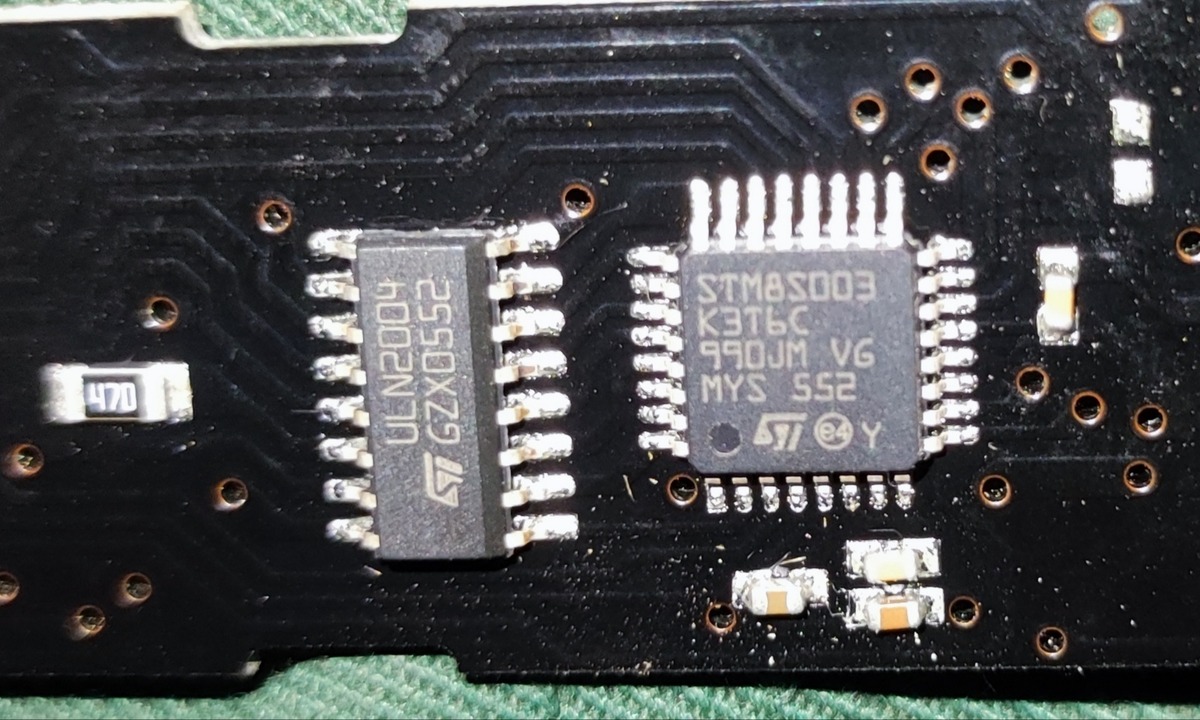
Nahaufnahme von zwei integrierten Schaltkreisen auf einer Leiterplatte
ULN2004 STMicroelectronics STM8S003 K3T6C 990JM VG MYS SS2 470
in „Touch-Bedienung aus Dunstabzugshaube“ · Mikrocontroller und Digitale Elektronik · · Platinenfotos
-
Datei
defines.h
<y) ? x : y) #define pinPULLUP(x,y,z) (z)?(PORT(x)|=(1<<y)):(PORT(x)&=~(1<<y))//0_no 1_up #define u8x uint8_t //_delay_us #else//notAvr #define u8x uint32_t #define PROGMEM typedef char PROGMEM prog_char; #define PGM_P const prog_char * #define PSTR(s) ((const PROGMEM char *)(s)) #define pgm_read_byte
in „Header Datei für Konfiguration erstellen“ · Mikrocontroller und Digitale Elektronik ·
-
Datei
eventcb_ctrl6.ino
---------------------- Objektinstanz von shiftreg595 erstellen Usage: shiftreg595::shiftreg595(uint8_t clk, uint8_t dat, uint8_t stb) ---------------------------------------------------------------------- */ shiftreg595 sr(2, 3, 15); // stm32 r3-board (PB7, PB6, PB13) // shiftreg595 sr(5, 3, A2); //
in „Schulnotenbewertung eines Arduino-Programms“ · Mikrocontroller und Digitale Elektronik ·
-
Datei
diskio.c
); } /* SPI1 Transfer Routine */ static uint8_t xchg_spi(uint8_t data) { while (SPI_I2S_GetFlagStatus(SPI1, SPI_I2S_FLAG_TXE) == RESET); /* Wait for SPIz Tx buffer empty */ SPI_I2S_SendData(SPI1,data); /* Send SPI1 data */ while (SPI_I2S_GetFlagStatus
in „STm32F103: Beispielcode der Chan FatFs zum Laufen bekommen“ · Mikrocontroller und Digitale Elektronik ·
-
Datei
main.c
---> DCMI_VSYNC PD2 ------> SDMMC1_CMD PA10 ------> USB_OTG_FS_ID PH14 ------> DCMI_D4 PI0 ------> S_TIM5_CH4 PC9 ------> I2S_CKIN PA8 ------> RCC_MCO_1 PC8 ------> SDMMC1_D0 PC7 ------> USART6_RX PH4 ------> USB_OTG_HS_ULPI_NXT PC6 ------> USART6_TX PF7 ------> ADC3_IN5 PF6 ------> ADC3_IN4 PB13 --
in „Probleme beim Debuggen mit SW4STM32 und und F7Disco“ · Mikrocontroller und Digitale Elektronik ·
-
PDF
CPSignal_Wallbox_mit__C.pdf
heute 17:37 wie würdest Du das CPSignal Wallbox +-12V mit einem uc erzeugen? 23s nachgedacht Ich würde das nicht mit zwei GPIOs und Transistoren improvisieren, sondern den µC nur das 1-kHz-PWM erzeugen lassen und damit einen analogen Umschalter zwischen +12 V und −12 V ansteuern.
in „saubere Rechtecksignalpegelwandlung 0/5V auf +12/-12V“ · Mikrocontroller und Digitale Elektronik ·
-
PDF
STM32F407VGT6-cjmcu.pdf
P0J1027 P0J1028 PB7/IIC1_SD7/IIC10SDA 0 0 0 0 P0U207PA12 PE12 29 P0J10297 28 P0J1030 PC5 PC6 PC7 PC8 PA13/JTMS- WDIO 72S0SWDIO P0U2072 P0U2444 PE13PE13 GND 29 30 3.3V 1 1 0 0 0 0 N0PA14/JTCK0SWCLK PA13 PE13 P0U2045 N0PE14 31 P0J1031 P0J1032 O O 000nF 100nF 000nF 100nF 0 0 PA14/JTCK-SWCLK 76 P0U207PA14
in „Schaltplan/LED-Belegung CJMCU-407 Board mit STM32F407VG“ · Mikrocontroller und Digitale Elektronik ·
-
PDF
MINI_STM32F407VGT6.pdf
P0J1027 P0J1028 PB7/IIC1_SD7/IIC10SDA 0 0 0 0 P0U207PA12 PE12 29 P0J10297 28 P0J1030 PC5 PC6 PC7 PC8 PA13/JTMS- WDIO 72S0SWDIO P0U2072 P0U2444 PE13PE13 GND 29 30 3.3V 1 1 0 0 0 0 N0PA14/JTCK0SWCLK PA13 PE13 P0U2045 N0PE14 31 P0J1031 P0J1032 O O 000nF 100nF 000nF 100nF 0 0 PA14/JTCK-SWCLK 76 P0U207PA14
in „STM32F407VGT6 China Board not working Tips?“ · Mikrocontroller und Digitale Elektronik ·
-
Datei
stm32f4x7_eth.h
**** */ /* Define to prevent recursive inclusion -------------------------------------*/ #ifndef __STM32F4x7_ETH_H #define __STM32F4x7_ETH_H #ifdef __cplusplus extern "C" { #endif /* Includes ------------------------------------------------------------------*/ #include "eth_conf.h" /** @addtogroup STM32F4x7
in „stm32f4xx lan8720 uip“ · Mikrocontroller und Digitale Elektronik ·
-
 Bild
Bild
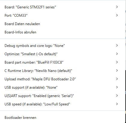
Konfigurationsmenü für STM32F1 Blue Pill Board
Board: "Generic STM32F1 series" Port: "COM33" Board Daten neuladen Board-Infos abrufen Debug symbols and core logs: "None" Optimize: "Smallest (-Os default)" Board part number: "BluePill F103C8" C Runtime Library: "Newlib Nano (default)" Upload method: "Maple DFU Bootloader 2.0" USB support (if available): "None" U(S)ART support: "Enabled (generic Serial)" USB speed (if available): "Low/Full Speed" Bootloader brennen
in „Bluepill STM32F103C8x Arduino Bootloader“ · Mikrocontroller und Digitale Elektronik · · Screenshots
-
Datei
main.c
"main.h" volatile uint8_t tx_restart = 1; volatile uint16_t dcnt; volatile uint8_t cntTouchread; volatile uint8_t cntTouchcalc; volatile uint16_t cntAlive; volatile uint8_t cntInA; volatile uint8_t cntInB; volatile uint8_t btnAlock; volatile uint8_t btnBlock; volatile uint8_t cntOutA; volatile uint8_t cntOutB; volatile uint8_t stateOutA; volatile uint8_t stateOutB; volatile uint16_t waitInA; volatile uint16_t waitInB; volatile uint16_t adcValueArrayA
in „2 Kanal Touch Button Haussteuerungserweiterung“ · Projekte & Code ·
-
PDF
eGC.pdf
s s s s s s s s s s s s s VRAM_A8 PIIC2IO_L52P_M3A8_3 e e e e e e e e e e e e e e e e VRAM_A9 PIIC2IO_L52N_M3A9_3 62R R R R R R R R R R R R R R R R VRAM_A10 PIIC2IO_L51P_M3A10_3 VRAM_A[0..14] VRAM_A11
in „[Suche] Interessierte(n) an Projekt (ARM/FPGA)“ · Mikrocontroller und Digitale Elektronik ·
-
Datei
led_an_aus_wechsel.c
#include "stm8s_conf.h" void main(void) { /* Resetten */ GPIO_DeInit(GPIOD); /* Initialisieren */ GPIO_Init(GPIOD, GPIO_PIN_ALL, GPIO_MODE_OUT_PP_LOW_FAST); /* Lässt die LED blinken */ for(;;) { u16 d; for (d = 0
in „Handbuch STM8S Discovery“ · Mikrocontroller und Digitale Elektronik ·
-
Datei
rfm12B_STM.c
: None *******************************************************************************/ #define lo8(x) ((uint16_t)(x)&0xff) #define hi8(x) ((uint16_t)(x)>>8) uint16_t crc_ccitt_update(uint16_t crc, uint8_t data) { data ^= lo8 (crc); data ^= data << 4; return ((((uint16_t)data << 8) | hi8 (crc)) ^ (
in „ST32F103 ---> AVR RFM12B“ · Mikrocontroller und Digitale Elektronik ·
-
PDF
DAT-31-PP.pdf
4000 Frequency (MHz) Frequency (MHz) RETURNLOSS INS11 (Major Attenuation Steps)@+25°C RETURN LOSS IN S11 (Major Attenuation Steps)@+25°C 60 60 ATT=0dB ATT=0dB ATT=1dB ATT=1dB 50 50 ATT=2dB ATT=2dB ATT=4dB ATT=4dB 40 40 B ATT=8dB B ATT=8dB ( ATT=16dB ( ATT=16dB 30 30 ATT=31dB ATT=31dB 20 20 10 10 0 0 0
in „Signalpegel mit Pin-Dioden einstellen?“ · HF, Funk und Felder ·