-
Datei
auf_u_abdimmen.txt
Schaltung : //------------------------------------------------------------------------- // Prozessor : ATmega8 // Takt : 4000000 Hz // Sprache : C // Datum : 2.3.2012 // Version : 1.0 // Autor : // Programmer: // Port : //------------------------------------------------------------------------- // created
in „LEDs langsam auf- und wieder abdimmen“ · Mikrocontroller und Digitale Elektronik ·
-
Datei
CAN_Init.c
*********************************************************************/ /* Purpose: Test for AT90CAN128 controller with standard ID */ /* Version: 1.0 */ /* Author: Mike Schaub */ /* Date: 19.10.2005 */ /* www: www.microcontroller-starterkits.de */ /* email: mike@microcontroller-starterkits.de */ /* Software: WinAVR to compile */ /* Hardware: ATMegaEvoBoard */ /****************************************************************************/ void set_can_baudrate(unsigned int br) // Werte sind für F_OSZ = 16 MHz! { switch(br) { case 1000: CANBT1 =
in „AT90CAN128 Timer“ · Mikrocontroller und Digitale Elektronik ·
-
Datei
AVR8_Burn_O_Mat_Config.xml
caption="4.0V (3.7V - 4.5V)" Fuse1="0" Fuse2="0"/> </BrownOutDetection> <OscillatorOptions Type="ATmega8" /> </AVR> <AVR name="m16" caption="ATmega16"> <Fuse name="OCDEN" bit="7" fuseByte="hfuse" default="1" desc="Enable OCD (on chip debug)" mode="expert"/> <Fuse name="JTAGEN" bit="6" fuseByte="hfuse
-
 Bild
Bild
Schaltplan mit Mikrocontroller und mehreren Transistoren
ATMEGA328P, R1, R2, R3, R4, R5, R6, R7, R8, R9, R10, R11, R12, R13, R14, R15, R16, R17, R18, R19, R20, R21, R22, R23, R24, R25, R26, R27, R28, R29, R30, R31, R32, R33, R34, R35, R36, R37, R38, R39, R40, R41
in „MCP23017 und UDN2981A“ · Mikrocontroller und Digitale Elektronik · · Schaltpläne
-
Datei
uart.txt
www.hpinfotech.com Project : Version : Date : 09.08.2007 Author : F4CG Company : F4CG Comments: Chip type : ATmega8535 Program type : Application Clock frequency : 8,000000 MHz Memory model : Small External SRAM size : 0 Data Stack size : 128 *****************************************************/ #include <mega8535
in „UART Senden und empfangen“ · Mikrocontroller und Digitale Elektronik ·
-
Datei
auf_u_abdimmen.txt
Schaltung : //------------------------------------------------------------------------- // Prozessor : ATmega8 // Takt : 4000000 Hz // Sprache : C // Datum : 2.3.2012 // Version : 1.0 // Autor : // Programmer: // Port : //------------------------------------------------------------------------- // created
in „LEDs langsam auf- und wieder abdimmen“ · Mikrocontroller und Digitale Elektronik ·
-
Datei
io_expander.c
// io_expander.c // for NerdKits with ATmega168 #define F_CPU 14745600 #include <stdio.h> #include <avr/io.h> #include <avr/interrupt.h> #include <avr/pgmspace.h> #include <inttypes.h> #include "../libnerdkits/i2cmaster.h" #include "../libnerdkits
in „MCP23016 Port Expander Input Realisieren“ · Mikrocontroller und Digitale Elektronik ·
-
PDF
Sinuswechselrichter.pdf
des ATMega162 zieht den Pegel des Reset-Pins immer auf HIGH. Das führt dazu, dass der Resetpin des ATMega162 durch die Schaltung der USV nicht angesteuert werden kann und der diskrete Watchdog und die diskrete
in „Wechselrichter Spannung und Frequenz steuerbar für Teichpumpe“ · Haus & Smart Home ·
-
Datei
mispav.htm
h3><a name="versionen"></a>Versionen</h3> <a href="../../../../h/home/html/etronik/atmel/atmel_c_atmega164p_324p_644p_doc7674.pdf">ATMega644P</a>: <a href="../../../../h/home/html/etronik/atmel/atmel_c_atmega164p_324p_644p_40002071A.pdf">(*)</a>: ROM: 64KiB 65536 (0x10000) Bytes, RAM:4KiB 4096 RAM <br> <a href="../../../../h/home/html/etronik/atmel/atmel_c_atmega328_328p_168a_168pa_88a_88pa_48a_48pa.pdf">Atmega328</a>: ROM: 32KiB 32768 (0x8000), RAM 2KiB 2048 <br> <a href="../../../../h/home/html/etronik/atmel/atmel_c_atmega32_complete_doc2503.pdf">Atmega32
in „Implementierung von Menüs auf alphanumerischen Displays“ · Mikrocontroller und Digitale Elektronik ·
-
PDF
atmega_328.pdf
(5) 32A ATmega48A-AUR 32A ATmega48A-MMH (4) 28M1 20(3) 1.8 - 5.5 ATmega48A-MMHR (4)(5) 28M1 Industrial ATmega48A-MU 32M1-A (-40C to 8°C) (5) ATmega48A-MUR 32M1-A ATmega48A-PU 28P3 Note: 1. This device can also be
in „1 Wire mit Atmega328“ · Mikrocontroller und Digitale Elektronik ·
-
 Bild
Bild
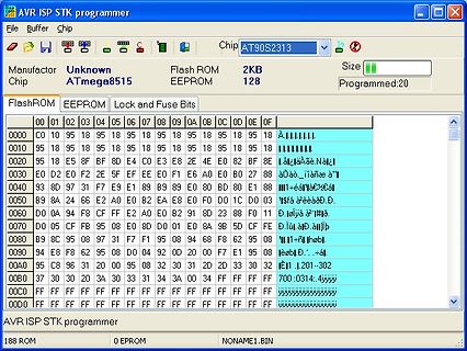
AVR ISP STK Programmer Software mit FlashROM Inhalt
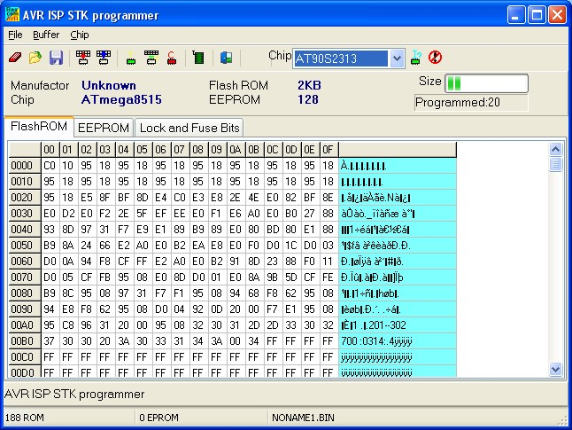
AVR ISP STK programmer File Buffer Chip Manufactor Unknown Chip ATmega8515 Flash ROM 2KB EEPROM 128 Size Programmed:20 FlashROM EEPROM Lock and Fuse Bits 0000 C0 10 95 18 95 18 95 18 95 18 95 18 A..IIIIIIII 0010 95 18 95 18 95 18 95 18 95 18 95 18 95 18 Ä.äÄä.Nঠ0020
in „LCD mit BASCOM an Port C“ · Mikrocontroller und Digitale Elektronik · · Screenshots
-
Datei
timer.txt
www.hpinfotech.com Project : Version : Date : 02.08.2007 Author : F4CG Company : F4CG Comments: Chip type : ATmega8535 Program type : Application Clock frequency : 8,000000 MHz Memory model : Small External SRAM size : 0 Data Stack size : 128 *****************************************************/ #asm .equ __lcd_port
in „sekundenzähler mit timer“ · Mikrocontroller und Digitale Elektronik ·
-
Datei
timer.txt
www.hpinfotech.com Project : Version : Date : 02.08.2007 Author : F4CG Company : F4CG Comments: Chip type : ATmega8535 Program type : Application Clock frequency : 8,000000 MHz Memory model : Small External SRAM size : 0 Data Stack size : 128 *****************************************************/ #asm .equ __lcd_port
in „sekundenzähler mit timer“ · Mikrocontroller und Digitale Elektronik ·
-
Datei
timer.txt
www.hpinfotech.com Project : Version : Date : 02.08.2007 Author : F4CG Company : F4CG Comments: Chip type : ATmega8535 Program type : Application Clock frequency : 8,000000 MHz Memory model : Small External SRAM size : 0 Data Stack size : 128 *****************************************************/ #asm .equ __lcd_port
in „sekundenzähler mit timer“ · Mikrocontroller und Digitale Elektronik ·
-
Datei
timer.txt
www.hpinfotech.com Project : Version : Date : 02.08.2007 Author : F4CG Company : F4CG Comments: Chip type : ATmega8535 Program type : Application Clock frequency : 8,000000 MHz Memory model : Small External SRAM size : 0 Data Stack size : 128 *****************************************************/ #asm .equ __lcd_port
in „sekundenzähler mit timer“ · Mikrocontroller und Digitale Elektronik ·
-
Datei
timer.txt
www.hpinfotech.com Project : Version : Date : 02.08.2007 Author : F4CG Company : F4CG Comments: Chip type : ATmega8535 Program type : Application Clock frequency : 8,000000 MHz Memory model : Small External SRAM size : 0 Data Stack size : 128 *****************************************************/ #asm .equ __lcd_port
in „sekundenzähler mit timer“ · Mikrocontroller und Digitale Elektronik ·
-
Datei
timer.txt
www.hpinfotech.com Project : Version : Date : 02.08.2007 Author : F4CG Company : F4CG Comments: Chip type : ATmega8535 Program type : Application Clock frequency : 8,000000 MHz Memory model : Small External SRAM size : 0 Data Stack size : 128 *****************************************************/ #define xtal 8000000L
in „sekundenzähler mit timer“ · Mikrocontroller und Digitale Elektronik ·
-
Datei
main.c
/* Control for a AD5293 digital poti via SPI. Controller: ATmega8 */ #include<avr/io.h> #include<util/delay.h> #include <avr/interrupt.h> #define DD_MOSI 3 #define DD_MISO 4 #define DD_SCK 5 #define DD_SS 2 #define DDR_SPI DDRB #define PORT_SPI PORTB void SPI_MasterInit
in „Digitales Poti AD5293 und ATmega8“ · Mikrocontroller und Digitale Elektronik ·
-
PDF
N2M_1_2010.pdf
Funktions- Taster ( S3 ) Reset- Taster ( S2 ) Mehrfarbige LED`s ( 8x ) IR – Empfänger Superhelle LED ATmega 128 2 x Hauptcontroller Ansicht Nibo 2 mit Grafikdisplay Eine kleine Ansicht, damit was findet. Seite | 1 Nun ein kleines Beispiel für ein Programm. Probiert es ruhig aus. Ich arbeite mit AVR/Studio
in „Nibo 2 Magazin“ · Mikrocontroller und Digitale Elektronik ·
-
 Bild
Bild
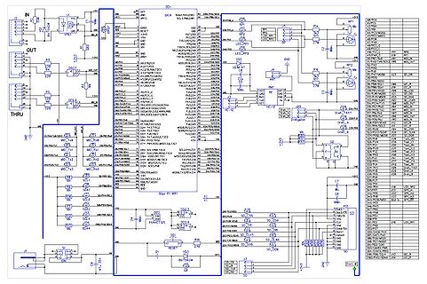
Schaltplan eines Mikrocontrollers mit Peripherie
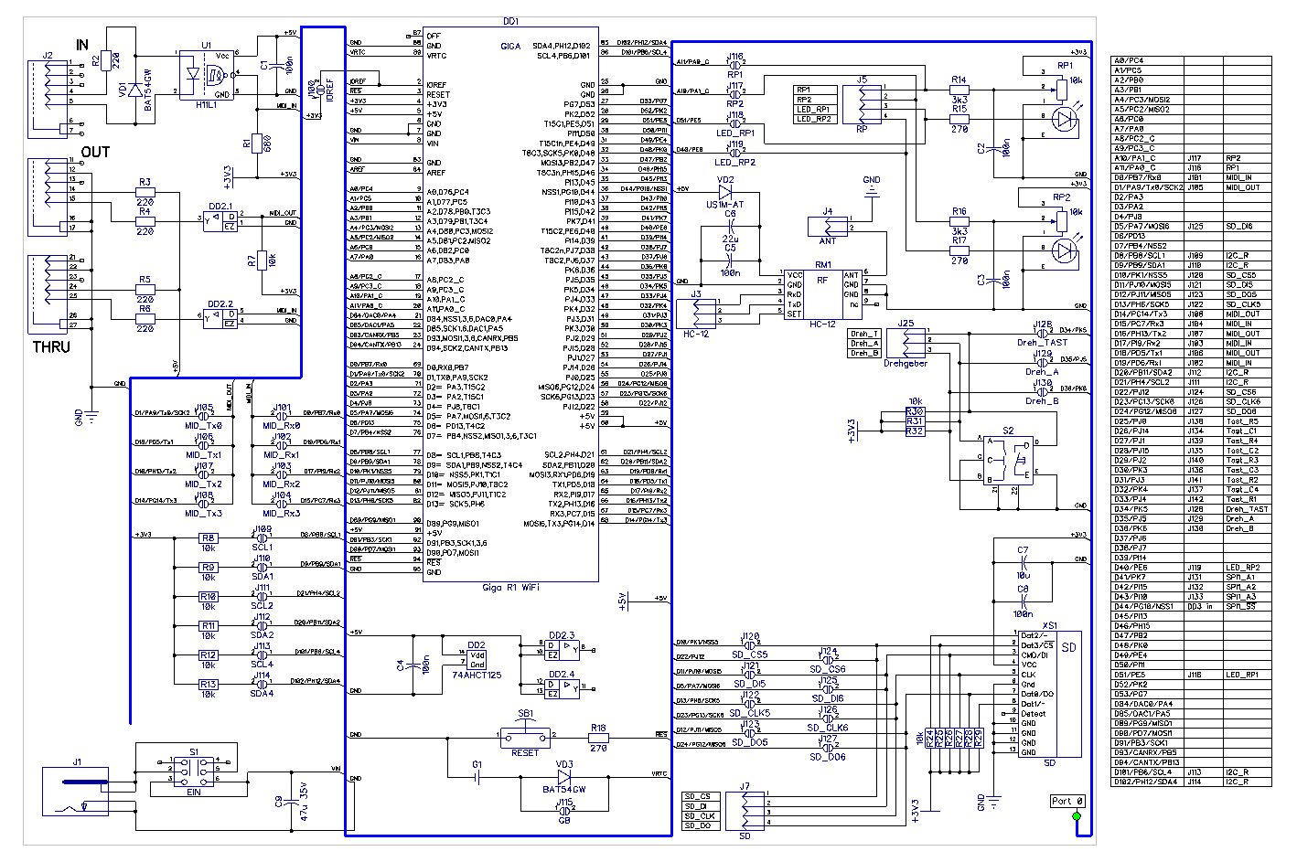
DD1, ATmega8, IN, OUT, THRU, +5V, GND, LED1 bis LED4, MD1 bis MD4, SD_CS bis SD_D6, RESET, J1, J2, J3, J4, J5, J6, J7, J8, J9, J10, J11, J12, J13, J14, J15, J16, J17, J18, J19, J20, J21, J22, J23, J24, J25, J26
in „Unerklärliches Verhalten von Spannungsfolger/Impedanzwandler (LM324)“ · Analoge Elektronik und Schaltungstechnik · · Schaltpläne
-
PDF
Profibus-Uart.pdf
hpinfotech.com Project : Version : Date : 13.06.2007 Author : F4CG Company : F4CG Comments: Chip type : ATmega128 Program type : Application Clock frequency : 11,059200 MHz Memory model : Small External SRAM size : 0 Data Stack size : 1024 *****************************************************/ #include <mega128
in „PROFIBUS->UART (ATMega128)->PC“ · Mikrocontroller und Digitale Elektronik ·
-
Datei
SHT.c
******************** Project: SHTxx demo program (V2.1) Filename: SHTxx_Sample_Code.c Prozessor: ATMega128 Compiler: GCC Autor: PB Copyrigth: ***********************************************************************************/ #include <avr/io.h> #include <avr/interrupt.h> #include <avr/signal.h> #include <inttypes.h> #include <avr/iom128.h> #include <inttypes.h> #include <math.h> #include <compat/ina90.h> #include <avr/delay.h> volatile void DATA(unsigned char set); volatile void SCK(unsigned char set); typedef union { unsigned int
in „Prolbem AVRStudio mit GCC und Log10 ??“ · Mikrocontroller und Digitale Elektronik ·
-
Datei
main.c
mit erstellt. http://www.mikrocontroller.net war eine gro0e Hilfe. * Ganz auf das Datenblatt des ATmega88PA konnte ich aber nicht verzichten. * * Heiko Jurgeleit, 19.03.2015 * jurgeleit.heiko(at)gmail.com * */ // CPU frequency for proper time calculation in delay function #define F_CPU 1000000UL #include
in „AVR - Drehgeber auslesen - optimiert für präzise Benutzereingaben“ · Projekte & Code ·
-
Datei
Protokoll.txt
Recv: 2 [32] avrdude: Recv: . [02] avrdude: stk500v2_getsync(): found STK500 programmer AVR Part : ATmega328P Chip Erase delay : 9000 us PAGEL : PD7 BS2 : PC2 RESET disposition : dedicated RETRY pulse : SCK serial program mode : yes parallel program mode : yes Timeout : 200 StabDelay : 100 CmdexeDelay
in „ATMega328P für MaXYposi flashen“ · Mikrocontroller und Digitale Elektronik ·
-
Datei
AVR-Studio2.txt
avrgcc\avr\include" -I"C:\Dokumente und Einstellungen\Root\Desktop\test-akkuboost\akku-test\." -mmcu=atmega32 -Wall -gdwarf-2 -std=gnu99 -DF_CPU=8000000UL -Os -funsigned-char -funsigned-bitfields -fpack-struct -fshort-enums -MD -MP -MT akkuboost2.o -MF dep/akkuboost2.o.d -c ../akkuboost2.c In file included
in „Suche Hilfe beim Compilieren von fertigem C-Code“ · Mikrocontroller und Digitale Elektronik ·
-
Datei
glcd-neu.asm
.include "m128def.inc" ;Includes the Atmega128 .def temp0 = R16 .def temp1 = R17 .def temp2 = R18 .def dataV1 = R19 .def dataV2 = R20 .def commandV = R21 ; User Constants .equ TXHOME = 0x40 .equ TXAREA = 0x41 .equ
-
Datei
main.c
#define DDR(x) (*(&x - 1)) /* address of data direction register of port x */ #if defined(__AVR_ATmega64__) || defined(__AVR_ATmega128__) /* on ATmega64/128 PINF is on port 0x00 and not 0x60 */ #define PIN(x) ( &PORTF==&(x) ? _SFR_IO8(0x00) : (*(&x - 2)) ) #else #define PIN(x) (*(&x - 2)) /* address
in „Alles schwarz nach Initial. bei Display (4x20, KS0076B)“ · Mikrocontroller und Digitale Elektronik ·
-
PDF
Powermeter.pdf
should then fit into 4kB and the microcontroller can be replaced by an ATmega48, for example. • Add functions such as remote reading, demand recording or multiple tariffs. Upgrade to ATmega168, for example, if the firmware exceeds 8kB. • Add integrated LCD support simply by migrating to ATmega169. No software is ever complete and there are probably as many potential improvements Meter Firmware as there are readers of this document. The good news is the firmware is open source and can be
in „230V Leistung erfassen mit ATmega128“ · Mikrocontroller und Digitale Elektronik ·
-
PDF
volt230.pdf
should then fit into 4kB and the microcontroller can be replaced by an ATmega48, for example. • Add functions such as remote reading, demand recording or multiple tariffs. Upgrade to ATmega168, for example, if the firmware exceeds 8kB. • Add integrated LCD support simply by migrating to ATmega169. No software is ever complete and there are probably as many potential improvements Meter Firmware as there are readers of this document. The good news is the firmware is open source and can be
in „Netzteil ohne Trafo“ · Mikrocontroller und Digitale Elektronik ·
-
PDF
energymeter.pdf
should then fit into 4kB and the microcontroller can be replaced by an ATmega48, for example. • Add functions such as remote reading, demand recording or multiple tariffs. Upgrade to ATmega168, for example, if the firmware exceeds 8kB. • Add integrated LCD support simply by migrating to ATmega169. No software is ever complete and there are probably as many potential improvements Meter Firmware as there are readers of this document. The good news is the firmware is open source and can be
in „Leistungsmessung über Shunt?“ · Analoge Elektronik und Schaltungstechnik ·
-
PDF
doc2566.pdf
should then fit into 4kB and the microcontroller can be replaced by an ATmega48, for example. • Add functions such as remote reading, demand recording or multiple tariffs. Upgrade to ATmega168, for example, if the firmware exceeds 8kB. • Add integrated LCD support simply by migrating to ATmega169. No software is ever complete and there are probably as many potential improvements Meter Firmware as there are readers of this document. The good news is the firmware is open source and can be
in „Cadsoft Eagle“ · Platinen ·
-
Datei
dds-seq.asm
Z-Pointer zeigt immer schon auf die richtige. Die Amplitude kommt aus einer ; Multiplikation - der ATmega8 hat einen Hardware-Multiplizierer, mul kostet ; also nur zwei Takte: ; ; Ausgabe = 128 + amp * (Tabellenwert - 128) / 256 ; ; gerechnet als (Wert*amp)>>8 + ampbias, wobei die Hauptschleife ; ampbias = 128 - amp/2 mitfuehrt. Bei amp = 0 kommt exakt 128 heraus, also ; Stille in der Mittellage, ohne Gleichspannungssprung. ; ; mul schreibt sein Ergebnis fest nach R1:R0. Deshalb liegt das Null-Register ;
in „Claude Code trifft AVR-Assembler: vom Chip in den Browser mit einem Prompt“ · Mikrocontroller und Digitale Elektronik ·
-
Datei
mocolock_rotor.bas
Rotor) ' ' Layout und Programmierung by HELLMARS (C) Helmar Müller ' Stand 15.10.2009 ' HW: 2.1 ' - ATMega32, 16MHz Quarz extern ' - Erfassung der Drehbewegung über Hall-Sensor ' - erweiterte Resetschaltung analog Ray ' ' SW: 3.0 ' - Darstellung von Bild- und Textdaten aus Flash-Speicher ' - Umwandlung
in „Propeller Uhr“ · Mikrocontroller und Digitale Elektronik ·
-
Datei
avrdude_ice_failure.txt
bytes avrdude: jtag3_recv(): Got message seqno 0 (command_sequence == 0) [general] OK AVR Part : ATmega1284P Chip Erase delay : 55000 us PAGEL : PD7 BS2 : PA0 RESET disposition : dedicated RETRY pulse : SCK serial program mode : yes parallel program mode : yes Timeout : 200 StabDelay : 100 CmdexeDelay
in „avrdude / Atmel ICE“ · Mikrocontroller und Digitale Elektronik ·
-
PDF
rs232_2_twi_readme.pdf
Taktet den TWI-Bus durch Einstellen von TWBR auf 64 -4 Taktet den TWI-Bus durch Einstellen von TWBR auf 128 -5 Taktet den TWI-Bus durch Einstellen von TWBR auf 255 Der resultierende TWI-Takt ist abhängig vom CPU-Takt -x Taktet den TWI-Bus auf 100KHz, das ist die default-Einstellung beim Programmstart -b|d
in „Terminal / TWI-Adapter für Mega8 in C“ · Projekte & Code ·
-
Datei
Fconverter.c
. Bei fehlendem Eingangssignal wird die niedrigste Frequenz ausgegeben. Das Programm ist für den ATmega48 geschrieben, laeuft aber auch ohne Aenderung direkt auf einem ATmega88. Beispielhaft wird hier in "main()" die Berechnung: frequenz = frequenz * 1.12246; durchgefuehrt, wodurch die Ausgangsfrequenz
in „Frequenz verlangsamen“ · Mikrocontroller und Digitale Elektronik ·
-
Datei
Eisenbahn_Tiny45.c
LED //* für den Einsatz auf Modelleisenbahnen als Lichtsignal für //* Flugsicherungs - Lichter //* ATmega8 @ 8 MHz //* //* //***************************************************************************** #define F_CPU 8000000L #include <inttypes.h> #include <avr/io.h> #include <util/delay.h> #include <avr
in „ATtiny45 10bit-PWM“ · Mikrocontroller und Digitale Elektronik ·
-
Datei
serverinfo.htm
/tr> <tr><td><font face="Arial,Helvetica">Prozessor:</font></td><td><font face="Arial,Helvetica">ATmega128</font></td></tr> <tr><td><font face="Arial,Helvetica">LAN-Interface:</font></td><td><font face="Arial,Helvetica">XPORT Direct+</font></td></tr> <tr><td><font face="Arial,Helvetica">SD-Card:</font
-
Datei
timer.c
if EXTCLOCK==1 TIMSK = 0x00; ASSR |= (1<<AS2); TCNT2 = 0x00; TCCR2B = 0x05; OCR2B = 255; //(32768 / 128) - 1 #if defined (__AVR_ATmega644__) while(ASSR & 0x11); #else while(ASSR & 0x07); #endif TIMSK |= (1<<OCIE2A); #else TIMSK |= (1 << OCIE1A); TCCR1B |= (1<<WGM12) | (1<<CS10 | 0<<CS11 | 1<<CS12); TCNT1
-
Datei
usart_tests.c
/* usart tests fuer atmega128a1 * (c) fabian klabacher * erstellt: 13:08.11 / 20:05 * zuletzt bearbeitet: 14.08.11 / 19:16 */ #define F_CPU 32000000 // MPU-clock #define BAUD_VAL 115200 // baudrate fuer usart-uebertragung #define
in „ATxmega USART Hilfe“ · Mikrocontroller und Digitale Elektronik ·
-
PDF
AVR-C-Tutorial.pdf
wiki/AVR-GCC-TutoriStand:13.02.2005 # Kommentare in Makefiles beginnen mit einem Doppelkreuz ... # ATmega8 at work MCU = atmega8 # oder MCU = atmega16 # oder MCU = at90s8535 # oder ... ... Quellcode-Dateien einstellen Den Namen der Quellcodedatei welche die Funktion main enthält, wird hinter TARGET eingetragen
in „AVR-C-Tutorial“ · Mikrocontroller und Digitale Elektronik ·
-
PDF
CFAG12864BTFHV_v3.0.pdf
resistance VDDV =EEV K Ω (VDIV- Ci R ON Load current = ±150μA - - 1.5 Operating current IDD1 Master mode; 1/128duty - - 1.0 mA (3) IDD2 Slave mode; 1/128 duty - - 200 μA (4) Supply current EE Master mode; 1/128 duty - - 100 (5) Operating Frequency fOP1 Master mode; External clock 50 - 600 kHz fOP2 Slave mode
in „avr asm LCD Problem“ · Mikrocontroller und Digitale Elektronik ·
-
Datei
m8535def.inc
L Y ;* ;* Number :AVR000 ;* File Name :"m8535def.inc" ;* Title :Register/Bit Definitions for the ATmega8535 ;* Date : April 16th, 2002 ;* Version :1.00 ;* Support telephone :+47 72 88 43 88 (ATMEL Norway) ;* Support fax :+47 72 88 43 99 (ATMEL Norway) ;* Support E-mail :support@atmel.no ;* Target MCU :ATmega8535 ;* ;* DESCRIPTION ;* When including this file in the assembly program file, all I/O register ;* names and I/O register bit names appearing in the data book can be used. ;* In addition, the six
in „include für AT Mega 8538“ · Mikrocontroller und Digitale Elektronik ·
-
Datei
m8535def.txt
L Y ;* ;* Number :AVR000 ;* File Name :"m8535def.inc" ;* Title :Register/Bit Definitions for the ATmega8535 ;* Date : April 16th, 2002 ;* Version :1.00 ;* Support telephone :+47 72 88 43 88 (ATMEL Norway) ;* Support fax :+47 72 88 43 99 (ATMEL Norway) ;* Support E-mail :support@atmel.no ;* Target MCU :ATmega8535 ;* ;* DESCRIPTION ;* When including this file in the assembly program file, all I/O register ;* names and I/O register bit names appearing in the data book can be used. ;* In addition, the six
in „Servomotor ansteuern, kein Interrupt!!!“ · Mikrocontroller und Digitale Elektronik ·
-
Datei
main.c
******************************************************* // File........: main.c // Target(s)...: ATmega328p // Compiler....: AVR-GCC // Description.: ADC mit ATmega328p auf Arduino Nano3 //*************************************************************************** //#include <inavr.h> //#include <stdint.h
in „ADC in C unter WinAVR ärgert“ · Mikrocontroller und Digitale Elektronik ·
-
PDF
Hausbus_for_everyone.pdf
Data + 2Byte CRC16 3.3. Clients Jeder Client besteht aus einem MAX485/ADM483 Bustreiber und einem ATMega mit Hardware UART. • schaltbare Steckdose • Lichtschalter (Relay + beliebig viele Taster) • Dimmer • Rollosteuerung • Heizungssteuerung • etc. 3.3.1. Stromsparen an den Clients Die Clients schlafen grundsätzlich. Das heißt, der ATMega befindet sich im sleep Zustand. Er wird nur geweckt, wenn er gebraucht wird. Mit einem Interrupt an der UART oder mit einem Interrupt von einem Sensor (Taster, ...). 3.4. Stromversorgung Die Stromversorgung
-
PDF
Hausbus_for_everyone.pdf
Data + 2Byte CRC16 3.3. Clients Jeder Client besteht aus einem MAX485/ADM483 Bustreiber und einem ATMega mit Hardware UART. • schaltbare Steckdose • Lichtschalter (Relay + beliebig viele Taster) • Dimmer • Rollosteuerung • Heizungssteuerung • etc. 3.3.1. Stromsparen an den Clients Die Clients schlafen grundsätzlich. Das heißt, der ATMega befindet sich im sleep Zustand. Er wird nur geweckt, wenn er gebraucht wird. Mit einem Interrupt an der UART oder mit einem Interrupt von einem Sensor (Taster, ...). 3.4. Stromversorgung Die Stromversorgung
in „Gemeinsamer Hausbus: BusVerkabelung + Stecker“ · Haus & Smart Home ·
-
PDF
Hausbus_for_everyone.pdf
Data + 2Byte CRC16 3.3. Clients Jeder Client besteht aus einem MAX485/ADM483 Bustreiber und einem ATMega mit Hardware UART. • schaltbare Steckdose • Lichtschalter (Relay + beliebig viele Taster) • Dimmer • Rollosteuerung • Heizungssteuerung • etc. 3.3.1. Stromsparen an den Clients Die Clients schlafen grundsätzlich. Das heißt, der ATMega befindet sich im sleep Zustand. Er wird nur geweckt, wenn er gebraucht wird. Mit einem Interrupt an der UART oder mit einem Interrupt von einem Sensor (Taster, ...). 3.4. Stromversorgung Die Stromversorgung
in „Gemeinsamer Hausbus: UART Software“ · Haus & Smart Home ·
-
PDF
Hausbus_for_everyone.pdf
Data + 2Byte CRC16 3.3. Clients Jeder Client besteht aus einem MAX485/ADM483 Bustreiber und einem ATMega mit Hardware UART. • schaltbare Steckdose • Lichtschalter (Relay + beliebig viele Taster) • Dimmer • Rollosteuerung • Heizungssteuerung • etc. 3.3.1. Stromsparen an den Clients Die Clients schlafen grundsätzlich. Das heißt, der ATMega befindet sich im sleep Zustand. Er wird nur geweckt, wenn er gebraucht wird. Mit einem Interrupt an der UART oder mit einem Interrupt von einem Sensor (Taster, ...). 3.4. Stromversorgung Die Stromversorgung
in „Gemeinsamer Hausbus: RS485 Protokoll Software“ · Haus & Smart Home ·
-
Datei
test2.c
/* Eine 8-kanalige PWM mit verbessertem Lösungsansatz ATmega32 @ 8 MHz */ // Defines an den Controller und die Anwendung anpassen #define F_CPU 16000000L // Systemtakt in Hz #define F_PWM 100 // PWM-Frequenz in Hz #define PWM_STEPS 256 // PWM-Schritte pro Zyklus
in „Moodlight Sourcecode hilfe“ · Mikrocontroller und Digitale Elektronik ·