-
Datei
hd44780.c
CONDITIONS OF ANY KIND, either express or implied. * * @purpose HD44780 LCD Minimal interface for Atmega microcontrollers * http://www.pocketmagic.net/ */ #include <avr/io.h> #include "hd44780.h" #include "timeout.h" int g_nCurrentLine; // PURPOSE: flush channel E void lcd_toggle_e(void) { lcd_e_high(
in „Hilfe, komme nicht weiter. Temperatur von 0 bis -1 Grad kein negatives Vorzeichen.“ · Mikrocontroller und Digitale Elektronik ·
-
Datei
boot.h
see if it provides bootloader support. \todo From email with Marek: On smaller devices (all except ATmega64/128), __SPM_REG is in the I/O space, accessible with the shorter "in" and "out" instructions - since the boot loader has a limited size, this could be an important optimization. \par API Usage Example
in „Frage nach Bootloader-Source“ · Mikrocontroller und Digitale Elektronik ·
-
Datei
boot.h
see if it provides bootloader support. \todo From email with Marek: On smaller devices (all except ATmega64/128), __SPM_REG is in the I/O space, accessible with the shorter "in" and "out" instructions - since the boot loader has a limited size, this could be an important optimization. \par API Usage Example
in „[AVR] Register R0 und R1 direkt in C oder Inline Assembler“ · Mikrocontroller und Digitale Elektronik ·
-
 Bild
Bild
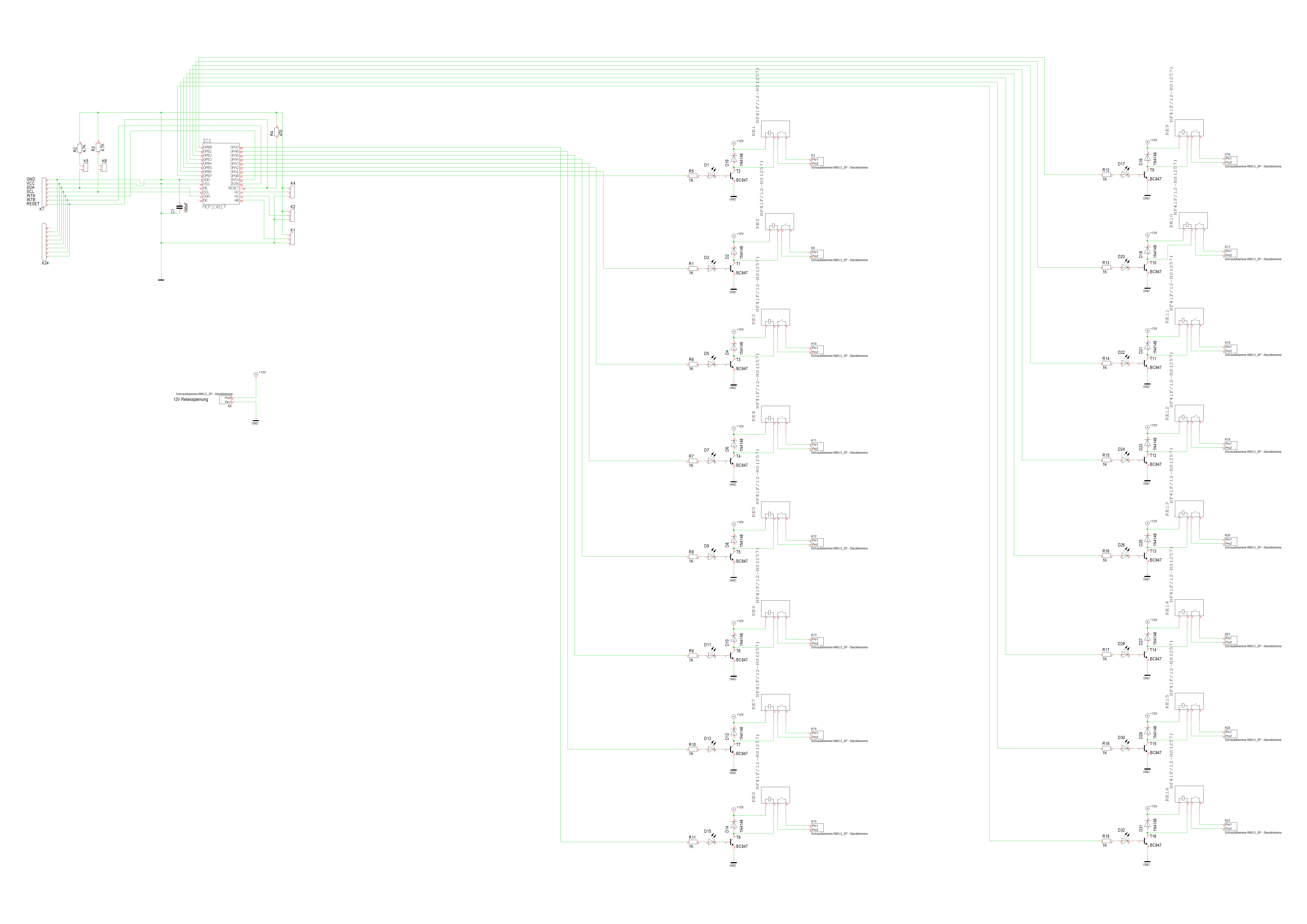
Schaltplan mit Mikrocontroller und mehreren Transistoren
ATMEGA328P, R1, R2, R3, R4, R5, R6, R7, R8, R9, R10, R11, R12, R13, R14, R15, R16, R17, R18, R19, R20, R21, R22, R23, R24, R25, R26, R27, R28, R29, R30, R31, R32, R33, R34, R35, R36, R37, R38, R39, R40, R41
in „MCP23017 und UDN2981A“ · Mikrocontroller und Digitale Elektronik · · Schaltpläne
-
Datei
my_eeprom.h
as some AVRs have problems with accessing EECR with STS instructions. For example, see errata for ATmega64. The code below also assumes that EECR and EEDR are in the I/O space. */ uint8_t __result; __asm__ __volatile__ ( "/* START EEPROM READ CRITICAL SECTION */ \n\t" "sbi %1, %2 \n\t" "in %0, %3 \n\t
in „optimierte der EEPROM-Leseroutinen“ · Mikrocontroller und Digitale Elektronik ·
-
Datei
Frequenzz__hler.c
Messbereich von 0 Hz bis etwa 1 Mhz Mit einem 16 MHz Quarz sind gut Frequenzen bis 4 MHz messbar. ATmega8/16/32 Roman Mittermayr AVRBUCH.DE */ #define TAKT 3686400 #include <avr/io.h> #include <avr/interrupt.h> #include <stdlib.h> #include <string.h> #include "rs232.h" volatile uint16_t Flanke1; volatile
in „problem mit atmega8 als Frequenzzähler“ · Mikrocontroller und Digitale Elektronik ·
-
Datei
twi.c
#include <avr/io.h> #define __AVR_ATmega64__ main(void) { // Input/Output Ports initialization // Port A initialization // Func7=In Func6=In Func5=In Func4=In Func3=In Func2=In Func1=In Func0=In // State7=T State6=T State5=T State4=T State3
in „TWI Source Code“ · Mikrocontroller und Digitale Elektronik ·
-
Datei
io_expander.c
// io_expander.c // for NerdKits with ATmega168 #define F_CPU 14745600 #include <stdio.h> #include <avr/io.h> #include <avr/interrupt.h> #include <avr/pgmspace.h> #include <inttypes.h> #include "../libnerdkits/i2cmaster.h" #include "../libnerdkits
in „MCP23016 Port Expander Input Realisieren“ · Mikrocontroller und Digitale Elektronik ·
-
Datei
Servo_00.c
/ //// lcd_gotoxy(0,1); //// //// lcd_puts("__TEXT__"); //// //// schlaf(8); //// //// //// //// ATMega16 //// //// CPU-Takt 1MHz //// //// Servo ist folgendermaßen //// //// angeschlossen: //// //// Black -> GND [Battery] //// //// Red -> +6V [Battery] //// //// Yellow -> PORTA0 //// ///////////////
in „Servo am Mikrocontroller“ · Mikrocontroller und Digitale Elektronik ·
-
Datei
AVR64EA32_b.cpp
/* * AVR64EA32 * RTC_PIT_002.cpp */ #include <avr/io.h> #include <util/delay.h> #include <avr/interrupt.h> #include <util/atomic.h> void initInternal20MHzOscillator (void) { // 20MHz mittels Fuse ausgewählt //
in „AVR64EA28: PIT-Interrupt“ · Mikrocontroller und Digitale Elektronik ·
-
PDF
Dds-1.pdf
Grund dafur i¨t die begrenz- te Auflo¨ung des Wandlers. Der hier verwendete 6 Bit-Wandler kann nur 2 = 64 6 unterschiedliche Spannungswerte erzeugen, so dass zwischen diesen Werten Sprunge¨ im Ausgangssignal entstehen. Um die unerwunsc¨ten Storung¨n zu entfernen, muss man zuerst einmal betrachten, was diese
in „Frage zu AVR DDS Funktionsgenerator“ · Mikrocontroller und Digitale Elektronik ·
-
 Bild
Bild
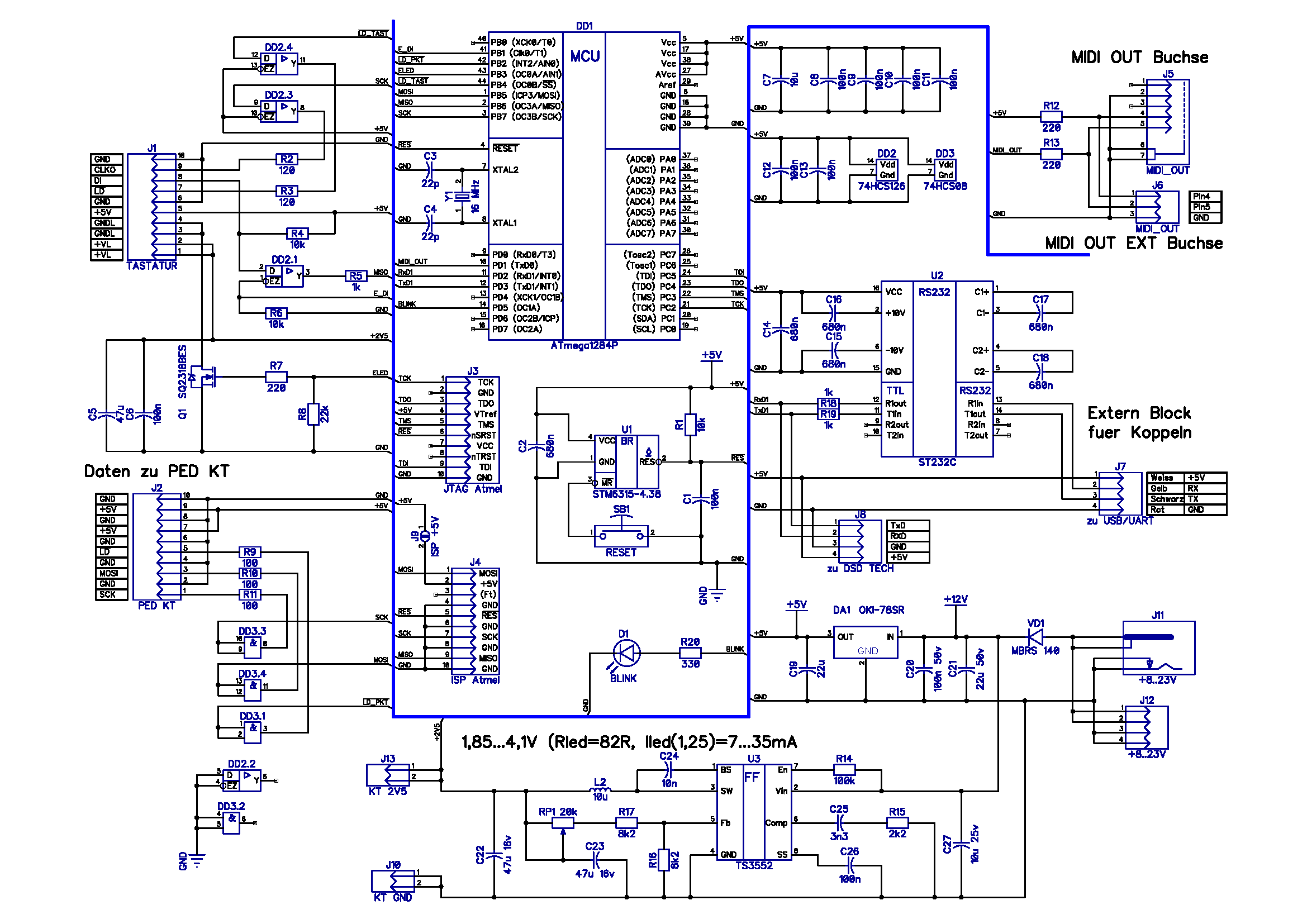
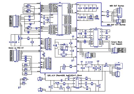
Schaltplan einer Mikrocontroller-Schaltung mit MIDI-Schnittstelle
DD1 MCU ATmega1284P, MIDI OUT, MIDI IN, USB, ST7232C, RS232, 5V, 12V, GND, R12 220, R13 220, R14 220, C1 100n, C2 100n, C3 100n, C4 100n, C14 100n, C15 100n, C16 100n, C17 100n, C18 100n, C19 100n, C20 100n, C21
in „Atmel Studio 4.19 unter W10X64“ · Mikrocontroller und Digitale Elektronik · · Schaltpläne
-
Datei
servo2.h
/* * servo2.h * * Der Code ist ausgelegt für einen ATMega8 mit 8Mhz ! * Der PreScaler wird auf 64 eingestellt * * Created on: 08.09.2010 * Author: bernd */ #ifndef SERVO2_H_ #define SERVO2_H_ #include <avr/io.h> #include <stdlib.h> #include <avr/interrupt.h
in „Servo dreht nur 90Grad“ · Mikrocontroller und Digitale Elektronik ·
-
Datei
ad9854_dl8mby.c
============================================ * AD9854 China Modul Controll via USB_2_RS232 and * ATMega32 MC-Chip. 03.05.2014 DL8MBY * ================================================== * compile with: gcc -o ad9854_dl8mby ad9854_dl8mby.c */ #include <stdio.h> #include <stdint.h> char text1[40]; #define
-
Datei
ATmega_SPI_Master.ino
Master Demo written by Robert Mollik, 2016 * * This demo uses the SPI protocol on a Arduino Uno R3 / ATmega8 controller * * The demo sends out a request ID depending, whether a temperature or humidity signal shall be obtained from the slave. Both signals * are datatype float, however get received as 4 bytes
in „ATtinyX5 und SPI Daisy-Chain“ · Mikrocontroller und Digitale Elektronik ·
-
PDF
N2M_1_2010.pdf
Funktions- Taster ( S3 ) Reset- Taster ( S2 ) Mehrfarbige LED`s ( 8x ) IR – Empfänger Superhelle LED ATmega 128 2 x Hauptcontroller Ansicht Nibo 2 mit Grafikdisplay Eine kleine Ansicht, damit was findet. Seite | 1 Nun ein kleines Beispiel für ein Programm. Probiert es ruhig aus. Ich arbeite mit AVR/Studio
in „Nibo 2 Magazin“ · Mikrocontroller und Digitale Elektronik ·
-
 Bild
Bild
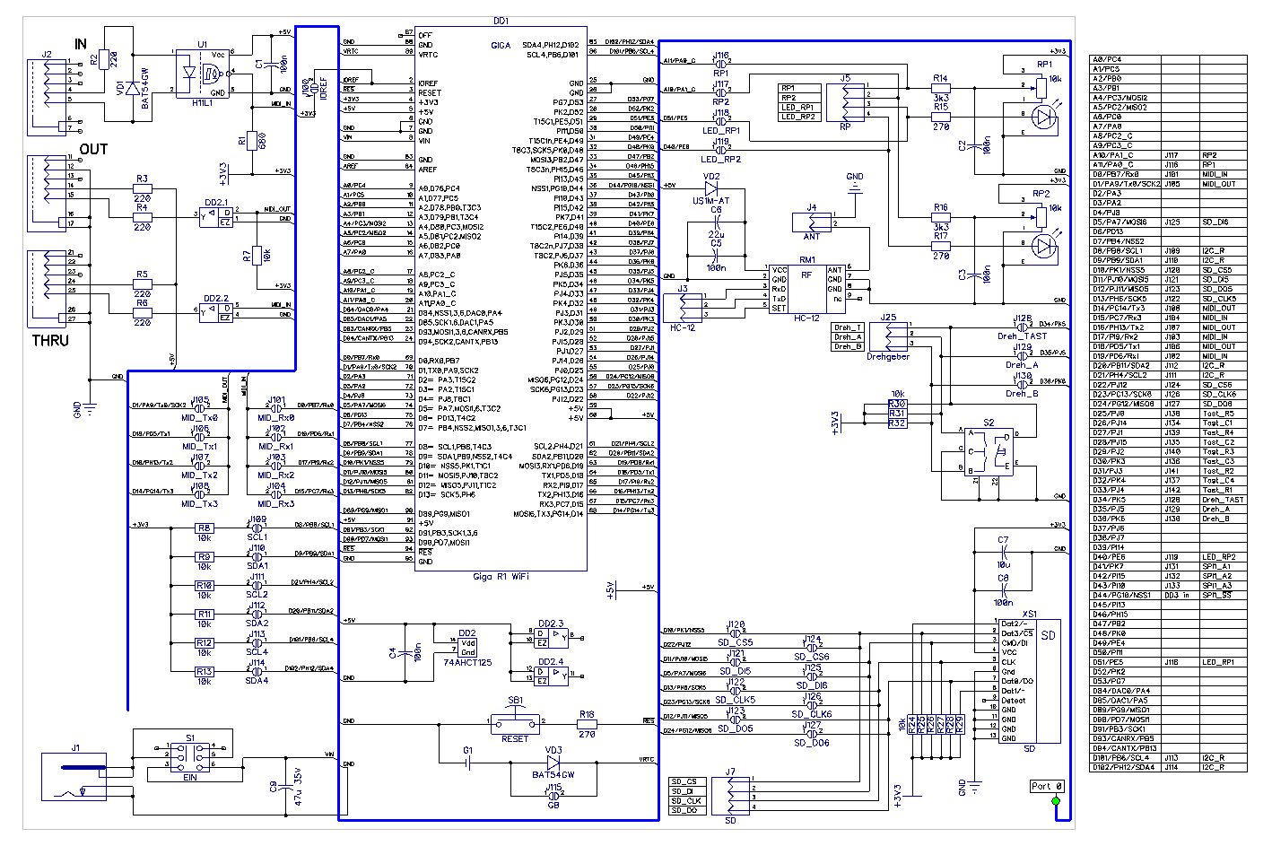
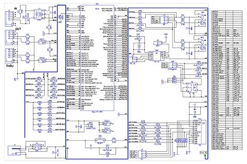
Schaltplan eines Mikrocontrollers mit Peripherie
DD1, ATmega8, IN, OUT, THRU, +5V, GND, LED1 bis LED4, MD1 bis MD4, SD_CS bis SD_D6, RESET, J1, J2, J3, J4, J5, J6, J7, J8, J9, J10, J11, J12, J13, J14, J15, J16, J17, J18, J19, J20, J21, J22, J23, J24, J25, J26
in „Unerklärliches Verhalten von Spannungsfolger/Impedanzwandler (LM324)“ · Analoge Elektronik und Schaltungstechnik · · Schaltpläne
-
Datei
All.txt
TQFP44 MICROCONTROLLER 3 IC1 MEGA168-P MEGA8-P DIL28-3 MICROCONTROLLER 3 IC1 MEGA128-A MEGA128-A TQFP64 MICROCONTROLLER 3 IC1 MAX232ECWE MAX232ECWE SO16L RS232 TRANSEIVER 3 IC1 ATMEGA644A ATMEGA644A TQFP44 8-bit Microcontroller with 64K Bytes In-System Programmable Flash 3 IC1 AT90S2313S AT90S2313S SO20L
in „[KiCad] Bibliotheksaufbau - Konzeptideen gesucht“ · Platinen ·
-
 Bild
Bild
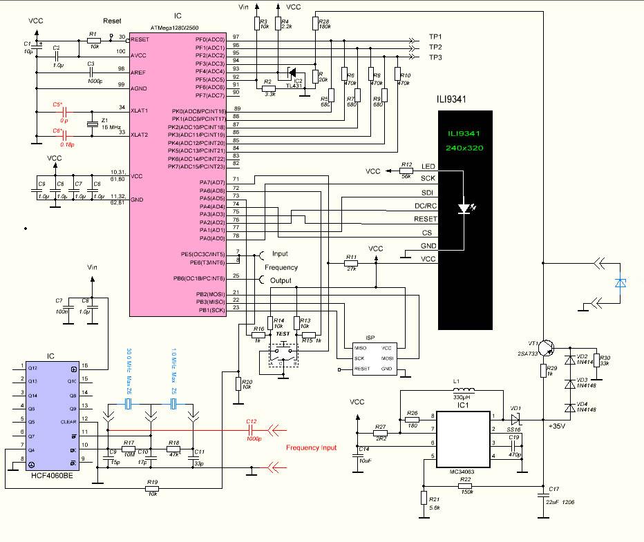
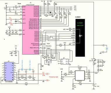
Schaltplan mit ATmega128 und ILI9341 Display
IC ATmega128GZ2560 VCC Reset R1 10k Reset PF0(ADC7) 97 PF1(ADC6) 95 PF2(ADC5) 93 PF3(ADC4) 92 PF4(ADC3) 90 PF5(ADC2) 89 PF6(ADC1) 87 PF7(ADC0) 85 PK0(ADC7/PCINT0) 83 PK1(ADC6/PCINT1) 81 PK2(ADC5/PCINT2) 79 PK3
in „AVR Transistortester MEGA2560 Shield“ · Markt · · Schaltpläne
-
 Bild
Bild
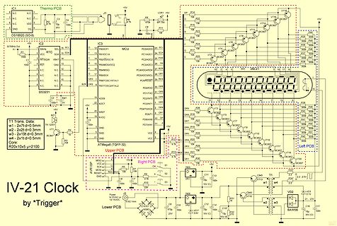
Schaltplan eines Mikrocontroller-basierten Systems mit zwei PCBs
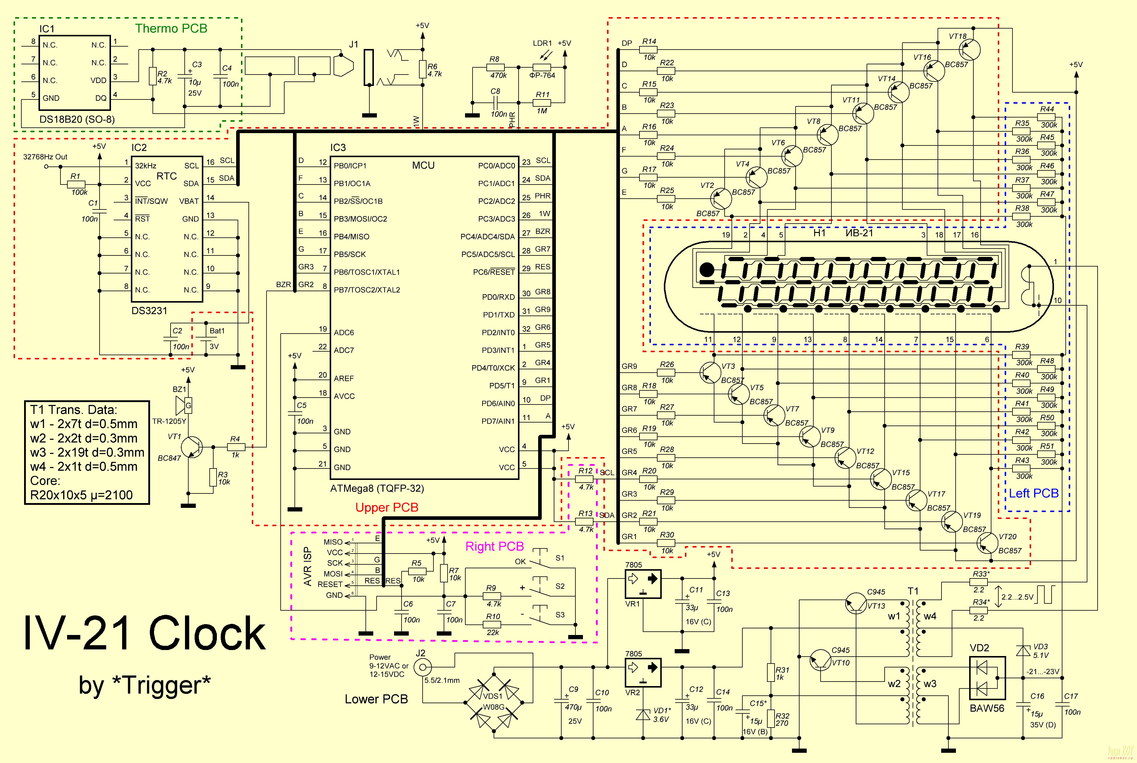
Thermo PCB IC1 DS18B20 (SO-8) IC2 ATmega (TQFP-32) IC3 MCU R2 376ohm C1 100n C3 C4 C5 C7 C8 C11 R3 4.7k R8 470k LDR1 R10 1M R15 10k R16 10k R17 10k R22 BC857 R23 BC857 R24 BC857 R25 BC857 R26 BC857 R27 BC857 R28 BC857 R29 BC857 R30 BC857
in „TPS61010 - Reset durch Lastprung verhindern“ · Analoge Elektronik und Schaltungstechnik · · Schaltpläne
-
Datei
main.c
LOW, D6 = HIGH) // PB5 (SCK) <-> SCK // PB3 (MOSI/OC2) <-> SDA // PB1 <-> CD // SPI PINBELEGUNG ATMEGA8 //------------------------ // PB5 (SCK) <-> SCK // PB4 (MISO) <-> --- // PB3 (MOSI/OC2) <-> SDA // PB2 (SS/OC1B) <-> --- #include <avr/io.h> #include "EXT_LCD_EADOG_UC1610.h" #define SCK PB5 #define
in „LCD Display defekt oder einstellungen ändern ?“ · Mikrocontroller und Digitale Elektronik ·
-
PDF
ATmega16M1_ISP.pdf
programming commands. 6. Exit Programming mode by power the device down or by bringing RESET pin to 0V. ATmega16M1/32M1/64M1 [DATASHEET] 280 8209E–AVR–11/2012
in „ISP Pins am ATMega16M1“ · Mikrocontroller und Digitale Elektronik ·
-
Datei
gamer.txt
stored directly to r31 ; next reads value for register or mode ; Author = Werner Braun ; Target = ATmega8 ; Date = 2012-02-04 ; ; PC6 = RESET ; PC5 = SCL TWI ; PC4 = SDA TWI ; PC3 = addon capacitor for filter ; PC2 = addon capacitor for filter ; PC1 = addon capacitor for filter ; PC0 = Glitch capacitor
in „DDS normal ?“ · Mikrocontroller und Digitale Elektronik ·
-
Datei
config.xml
RSTDISBL="0"/> <Setting caption="Normal reset input" RSTDISBL="1"/> </ResetDisable> </AVR> <AVR name="m64" caption="ATmega64"> <Fuse name="UNUSED_E7" bit="7" fuseByte="efuse" default="1" desc="unused" mode="expert"/> <Fuse name="UNUSED_E6" bit="6" fuseByte="efuse" default="1" desc="unused" mode="expert"/
in „Fuseeditor, grafische Benutzeroberfläche für AVRdude“ · Projekte & Code ·
-
Datei
MCP_Reg.h
www.microcontroller-starterkits.de */ /* email: */ /* Software: WinAVR to compile */ /* Hardware: ATMega128EvoBoard */ /****************************************************************************/ /****************** Port defintions ATMega128Evoboard ***********************/ #define HW_SPI PORTB #define
in „SPI-Problem mit MCP2515 und ATmega16“ · Mikrocontroller und Digitale Elektronik ·
-
Datei
probieren.asm
Display Anzeige ; Überarbeitet Version von Marco Reinke (DG1YIQ) ; Features: Festtext ; Anpassung an Atmega 8 von PIC 16F88 ; Version v0.2 .include "m8def.inc" ;Include Datei Atmega8 ;--- Reset und Interruptvectoren; VNr. Bezeichnung begin: rjmp main ; 1 Power ON RESET reti ; 2 Int0- Interrupt reti ; 3 Int1
in „Hat schonmal einer ein Opel TID ->erfolgreich<-angesteuert ?“ · Mikrocontroller und Digitale Elektronik ·
-
 Bild
Bild
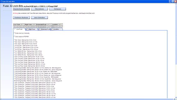
Software-Fenster zur Einstellung der Fuse- und Lock-Bits
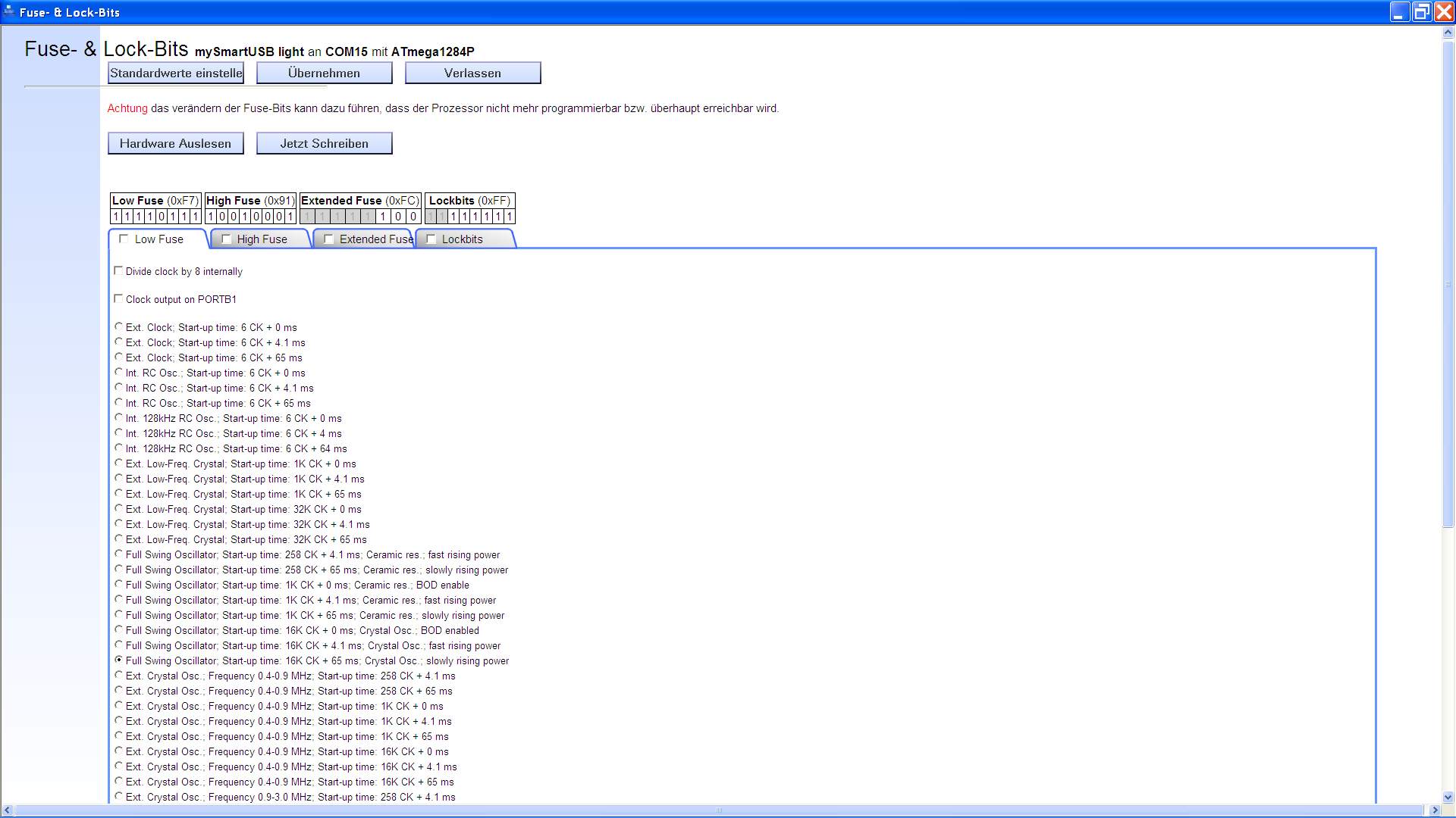
Fuse- & Lock-Bits mySmartUSB light an ATmega1284P Standardwerte einstelle Übernehmen Verlassen Achtung das verändern der Fuse-Bits kann dazu führen, dass der Prozessor nicht mehr programmierbar bzw. überhaupt erreichbar. Low Fuse (0xF7) High
in „Floppy FDD Diskette an AVR Mikrocontroller ATmega Beispiele Assembler“ · Projekte & Code · · Screenshots
-
Datei
test2.c
/* Eine 8-kanalige PWM mit verbessertem Lösungsansatz ATmega32 @ 8 MHz */ // Defines an den Controller und die Anwendung anpassen #define F_CPU 16000000L // Systemtakt in Hz #define F_PWM 100 // PWM-Frequenz in Hz #define PWM_STEPS 256 // PWM-Schritte pro Zyklus
in „Moodlight Sourcecode hilfe“ · Mikrocontroller und Digitale Elektronik ·
-
Datei
SPI.h
SPI_FOSC_DIV_8 0x05 #define SPI_FOSC_DIV_16 0x01 #define SPI_FOSC_DIV_32 0x06 #define SPI_FOSC_DIV_64 0x02 #define SPI_FOSC_DIV_128 0x03 #define SPI_RUNNING (!(SPSR & (1 << SPIF))) //**************************************************************************************** //Definitionen für den ATMega88
in „Atmega88- Daten von Sensoren auf Flash abspeichern“ · Mikrocontroller und Digitale Elektronik ·
-
PDF
IC_Brochure.pdf
rolled 2-phasesteppermotors 2,3and5phasesteppermotors essor possible. Together µ-stepResolution 6-bit{64,32,16,4,2,1} 8-bit with the Trinamic ‘Smart Max.Step 4MHz FrequencyperAxis 20kHzfullstep~1MHzµ-step Power’ Driver ICs TMC23x and TMC24x (StallGuard ) they form a complete RampShape trapezoid s-shaped
in „Schrittmotor Ansteuern - Lösungen“ · Mikrocontroller und Digitale Elektronik ·
-
PDF
Minimalistischer_GPS_Logger.pdf
werden fast immer vorausgesetzt. Das absolute „Muss“ scheinen dabei immer Microcontroller, etwa ATMEGA und eine SD-Karte zu sein. Doch es geht auch anders - hier nun etwas für den puristischen Bastler alter Schule, der nur Löten kann… Der GPS-Baustein L80 von Quectel Auch dieser Baustein ist minimalistisch
in „Minimalistischer GPS-Logger ohne µC und SD-Karte“ · Mikrocontroller und Digitale Elektronik ·
-
Datei
avrdude1.txt
_ [5f] M [4d] K [4b] 2 [32] avrdude: stk500v2_getsync(): found AVRISP mkII programmer AVR Part : ATMEGA32 Chip Erase delay : 9000 us PAGEL : PD7 BS2 : PA0 RESET disposition : dedicated RETRY pulse : SCK serial program mode : yes parallel program mode : yes Timeout : 200 StabDelay : 100 CmdexeDelay :
in „avrdude 5.6 unter Linux spinnt“ · Mikrocontroller und Digitale Elektronik ·
-
Datei
main.c
in their definition by a bit-wise inversion of a mask. For example, the FUSE_EESAVE fuse in the ATmega128 is defined as: \code #define FUSE_EESAVE ~_BV(3) \endcode \note The _BV macro creates a bit mask from a bit number. It is then inverted to represent logical values for a fuse memory byte. To combine
in „Tiefentladungsschutz mit Attiny und P-Kanal Fet“ · Mikrocontroller und Digitale Elektronik ·
-
PDF
AppNote_Atmel_RTC.pdf
Year 2000 Compliant Date Format • Can be used on all AVR Controllers with RTC Module • “C”-Code for ATMega103 Included 1 Introduction This application note describes how to implement a Real Time Clock (RTC) on AVR ® microcontrollers that features the RTC module. The implementation requires only one discrete
in „Atmel AVR Controller mit integrierter RTC“ · Mikrocontroller und Digitale Elektronik ·
-
Datei
sony_irf.bas
'------------------------- system daten $regfile = "m32def.dat" 'atmega 32 / 16 $crystal = 16000000 '16 MHz systemtakt $baud = 38400 'baud rate rs232 '------------------------- alias Sony_start Alias 0 Sony_start_bit Alias 1 Sony_data Alias 2 Sony_bits Alias 7 Sony_startbit
-
Datei
ADC_USART_Read_adc.h
+++++++++++++++++++++++++++++++++++++++++++++++++++++++ 8-Bit-Analog-Digital-Converter mit ATMEL ATmega8 to STK500 board, output on (PortB) --> LEDs Description: The ADC converts an analog input voltage to a 10-bit digital value through successive approximation. The minimum value represents GND and the
in „warnung:"[variable]may be used uninizialized"“ · Mikrocontroller und Digitale Elektronik ·
-
Datei
demo_spi_irq.c
// demo_spi_irq.c // ATmega64 with SPI on external shiftregisters HC 595 and HC 165 typedef unsigned char u8; #define LEDBYTES 15 // 15 external shiftregisters for led + switches, common clocked u8 led_bytes [LEDBYTES]; // data
in „Seltsames SPI Verhalten (Mega88, RFM12)“ · Mikrocontroller und Digitale Elektronik ·
-
Datei
Jesper_1x1536x8_9.txt
90,90,89,88,87,87,86,85,84,84,83,82,81,81,80,79 .db 79,78,77,76,76,75,74,73,73,72,71,71,70,69,69,68 .db 67,66,66,65,64,64,63,62,62,61,60,60,59,58,58,57 .db 56,56,55,54,54,53,53,52,51,51,50,49,49,48,48,47 .db 46,46,45,44,44,43,43,42,42,41,40,40,39,39,38,38 .db 37,36,36,35,35,34,34,33,33,32,32,31,31,30,30,29 .db 29,28,28,27,27,26,26,25,25,24,24,23,23,22,22,22
in „DDS normal ?“ · Mikrocontroller und Digitale Elektronik ·
-
Datei
PWM_test_2.c
******************************************************* // Copyright // Version /* * Chip type : ATMEGA 88 * Clock frequency : clock 20 Mhz Ein- und Ausgänge PORT B 0 (14) = PORT B 1 (15) = (OC1A/PCINT1) PWM Ausgabe, PORT B 2 (16) = (SS/OC1B/PCINT2) PWM Ausgabe, PORT B 3 (17) = PORT B 4 (18) = PORT B
in „Skalierung von Integerwerten“ · Mikrocontroller und Digitale Elektronik ·
-
PDF
AVR-Tutorial.pdf
von den 8bit-AVR-Controllern von Atmel erfüllt. Deshalb werde ich einen AVR, genauer gesagt den ATmega8 (bzw. den AT90S4433), in diesem Tutorial einsetzen. Der AT90S4433 wurde mittlerweile von Atmel abgekündigt, man sollte also wenn möglich einen ATmega8 verwenden. Ich werde mich trotzdem bemühen die
in „AVR-Tutorial als PDF bzw *.doc“ · Mikrocontroller und Digitale Elektronik ·
-
Datei
ODM100.c
* ******************************************************************************** * Processor : ATmega32 @ 8 MHz * Compiler : IAR (V4.30D) & GCC (WinAVR Version 10-01-2010) * Dot Matrix : 128 RGB x 128 * Driver IC : SSD1351 (Solomon Systech) * Interface : 8-bit 8080 Parallel ************************
in „Frage zum ODM100 OLED Bausatz von ELV“ · Mikrocontroller und Digitale Elektronik ·
-
Datei
oled1.c
* ******************************************************************************** * Processor : ATmega32 @ 8 MHz * Compiler : IAR (V4.30D) & GCC (WinAVR Version 10-01-2010) * Dot Matrix : 128 RGB x 128 * Driver IC : SSD1351 (Solomon Systech) * Interface : 8-bit 8080 Parallel ************************
in „AVR Oled Display odm 100-Wie ansteuern?“ · Mikrocontroller und Digitale Elektronik ·
-
Datei
oled.c
* ******************************************************************************** * Processor : ATmega32 @ 8 MHz * Compiler : IAR (V4.30D) & GCC (WinAVR Version 10-01-2010) * Dot Matrix : 128 RGB x 128 * Driver IC : SSD1351 (Solomon Systech) * Interface : 8-bit 8080 Parallel ************************
in „ODM100 OLED bleibt schwarz“ · Mikrocontroller und Digitale Elektronik ·
-
Datei
ODM100.c
* ******************************************************************************** * Processor : ATmega32 @ 8 MHz * Compiler : IAR (V4.30D) & GCC (WinAVR Version 10-01-2010) * Dot Matrix : 128 RGB x 128 * Driver IC : SSD1351 (Solomon Systech) * Interface : 8-bit 8080 Parallel ************************
in „SSD 1351 - OLED ansteuern“ · Mikrocontroller und Digitale Elektronik ·
-
Datei
lcd_ssd1306_gfx.c
include <math.h> #include <stdlib.h> #if PSC_I2C != 1 && PSC_I2C != 4 && PSC_I2C != 16 && PSC_I2C != 64 #error "Wrong prescaler for TWI at ATMega328p!" #elif SET_TWBR < 0 || SET_TWBR > 255 #error "TWBR out of range, change PSC_I2C or F_I2C !" #endif static uint8_t displayBuffer[DISPLAYSIZE]; uint8_t displayIsInverted
in „SSD1306/1309 Library zum Darstellen von Text auf OLED Displays“ · Projekte & Code ·
-
Datei
test_lcd_2.c
"lcd.h" /* ** constant definitions */ #ifndef CTC1 #define CTC1 WGM12 // for compatibility with ATmega #endif #define PHASE_A (PINC & 1<<PINC2) // PINC.2 #define PHASE_B (PINC & 1<<PINC3) // PINC.3 #define PHASE_E (PINC & 1<<PINC5) // PINC.5 #define ESECT __attribute__((section(".eeprom"))) uint8_t
in „Drehregler an uC - geht das?“ · Mikrocontroller und Digitale Elektronik ·
-
Datei
test_lcd_3.c
"lcd.h" /* ** constant definitions */ #ifndef CTC1 #define CTC1 WGM12 // for compatibility with ATmega #endif #define PHASE_A (PINC & 1<<PINC2) // PINC.2 #define PHASE_B (PINC & 1<<PINC3) // PINC.3 #define PHASE_E (PINC & 1<<PINC5) // PINC.5 #define ESECT __attribute__((section(".eeprom"))) uint8_t
in „Drehregler an uC - geht das?“ · Mikrocontroller und Digitale Elektronik ·
-
Datei
drehencoder.asm
******************************************************************* .include "m8def.inc" .device atmega8 ;-------------------------------------------------------------------------------- ;Register .def S =r5 ;SRegister .def temp =r16 .def itemp =r21 .def neu =r22 .def alt =r23 .def richtung=r24 ;----
-
Datei
test2.c
/* Eine 8-kanalige PWM mit verbessertem Lösungsansatz ATmega32 @ 8 MHz */ // Defines an den Controller und die Anwendung anpassen #define F_CPU 16000000L // Systemtakt in Hz #define F_PWM 100 // PWM-Frequenz in Hz #define PWM_STEPS 256L // PWM-Schritte pro Zyklus
in „Moodlight Sourcecode hilfe“ · Mikrocontroller und Digitale Elektronik ·
-
Datei
rcl.bas
01 $regfile = "m16DEF.dat" 'Microcontroller ATmega16 02 $crystal = 11059200 '11.0592MHz Quarz 03 $baud = 9600 'Baudrate 04 05 '---[ Variables ]--------------------------------------------------------------- 06 Dim Rs232kommando As String * 10 'erst
in „Bascom Programm“ · Mikrocontroller und Digitale Elektronik ·