-
Thread
CH32v003 PWM & Timer Probleme
GPIO_InitStructure.GPIO_Speed = GPIO_Speed_50MHz; GPIO_Init( GPIOD, &GPIO_InitStructure ); TIM_TimeBaseInitStructure.TIM_Period = 255; TIM_TimeBaseInitStructure.TIM_Prescaler = 0; TIM_TimeBaseInitStructure.TIM_ClockDivision = TIM_CKD_DIV2; TIM_TimeBaseInitStructure.TIM_CounterMode = TIM_CounterMode_Up
; TIM_TimeBaseInit( TIM2, &TIM_TimeBaseInitStructure); // 0xe79e = 20 Hz auf dem AVR TIM_SetCounter (TIM2, 0xe79e); TIM_SetAutoreload (TIM2, 0xe79e); NVIC_InitStructure.NVIC_IRQChannel = TIM2
-
 Bild
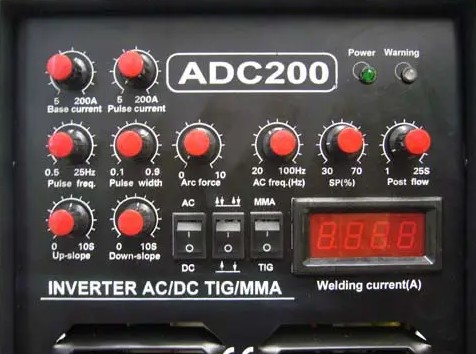
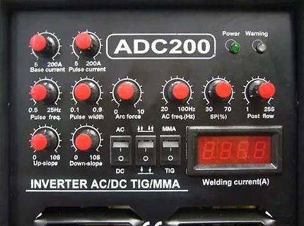
Bedienfeld eines ADC200 Inverter Schweißgeräts
ADC200 Power Warning 5 200A Base current 5 200A Pulse current 0.5 Pulse freq. 0.1 0.9 Pulse width 0 Arc force 10 20 100Hz AC freq.(Hz) 30 70 SP(%) 1 25S Post flow 0 10S Up-slope 0 10S Down-slope AC MMA DC TIG 8.8.8.8 Welding current
-
 Bild
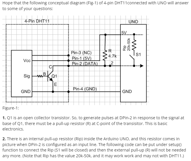
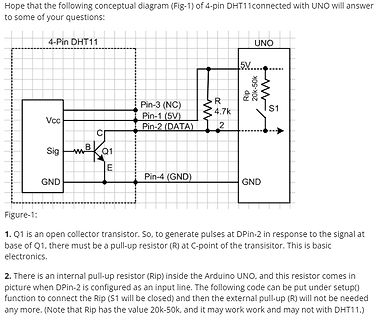
Schaltplan DHT11 mit Arduino UNO
some of your questions: 4-Pin DHT11 UNO Vcc Pin-3 (NC) Pin-1 (5V) Pin-2 (DATA) Pin-4 (GND) 5V Rip 20k-50k S1 R 4.7k Q1 Sig C B E GND Figure-1: 1. Q1 is an open collector transistor. So, to generate pulses at DPin-2 in response to the signal at base of Q1, there must be a pull-up resistor (R) at C-point
-
Thread
Visual Studio erlaubt keine Zeiger auf eine C++/CLI-Verweisklasse!
solchen Begrenzungen und nach vielen Jahren ist weiter beliebt und effektiv! In 80. und 90. Jahren 20. Jahrhundert kamen Schulabsolventen In Betrieben mit Pascal kenntnissen. Professoren in Schulen haben nur Pascal gelernt… In Betrieben mussten Sie aber in „C“ programmieren. Pointer Akrobatik war
kommt man auch nicht mehr weg. In 40 Jahren C++ ist eine Abhängigkeit entstanden. Haufenweise Code Bases sind in C++ geschrieben, rewrites - zu teuer. Stattdessen wird C++ regelmäßig geupdated auf Verlangen der Industrie. Der Nachwuchs ist auch nicht wirklich da für C++ - zu kompliziert, zu umfangreich
-
Thread
Ein Operationsverstärker mit Röhren-Diff-Amp (ECC83)
Bandbreite? Im Grunde ja nur weiterhin stabil bei Verstärkung 1. Mehr Gegenkopplungsreserve bei 20kHz für weniger Klirr.
zusätzlich gegen Masse, das sehe ich als parasitäre Kapazität auf der Leiterplatte) führt zu UGB 10MHz, bei 20kHz bleiben ~55dB Leerlaufverstärkung. Ich glaube so versuch ich es.
-
 Bild
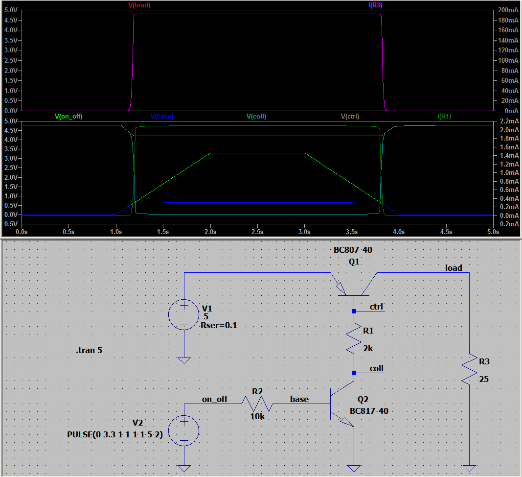
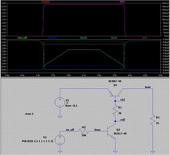
Schaltplan und Simulationsergebnisse einer Transistorschaltung
V(load) I(R3) 200mA 180mA 160mA 140mA 120mA 100mA 80mA 60mA 40mA 20mA 0mA 5.0V 4.5V 4.0V 3.5V 3.0V 2.5V 2.0V 1.5V 1.0V 0.5V 0.0V V(on_off) V(base) V(coll) V(ctrl) I(R1) 2.2mA 2.0mA 1.8mA 1.6mA 1.4mA 1.2mA 1.0mA 0.8mA 0.6mA 0.4mA 0.2mA 0.0mA -0.2mA 5.0V 4.5V 4.0V 3.5V
-
Thread
Wer vermisst noch die analoge Funktechnik - Erinnerungen
wollte der Hersteller für dieses Set haben... damals... und Heute gibt´s beim Discounter für rund 20€ Bluetooth Ohrstöpsel, die technologisch so fortschrittlich sind, das man sie sich 2004 vermutlich noch nicht mal hätte vorstellen können. Doch der Zugang. Das ist es, was auf der Strecke bleibt.
Europa und somit auch Deutschland, das Verschwinden der Auslandsrundfunksender (mit weit mehr als 20 Sprachdiensten, mehreren Sendezentren und mehren Stunden täglichen "richtigen" Programm auf KW) das Sender unterhalb von 100kW Sendeleistung an "richtigen" Antennen nur Not- und Füllsender waren usw.
-
Thread
100V Hilfsspannung - noch eine Freilaufdiode in der Schaltung benötigt?
Sowas in der Richtung ist das nix? STPSC20H065C Man muss ja nicht beide Dioden beschalten.
Karl B. schrieb im Beitrag #7438650: > STPSC20H065C Ungeeignet, weil viel zu dick für das winzige Wandlerchen.
-
Thread
Meadow Desktop - bequemer Hardware-Zugriff aus Windows
Resolver.Log.Info("Run..."); Resolver.Log.Info("Hello, Meadow.Windows!"); return base.Run(); } } [/c] Sodann bietet sich eine erstmalige Kompilation an, was auf Kommandozeilenebene in der Eingabeaufforderung nach folgendem Schema erfolgt: [c] C:\Users\tamha\source\repos
OEMSecrets-Bestpreis des hier verwendeten Bauteils (siehe https://www.oemsecrets.com/compare/FT2232H-56Q%20MINI%20MDL) liegt bei 30 EUR - bekommen Entwickler wieder niederschwelligen Zugang zu Hardware unter Nutzung von C# und Visual Basic. Schon aus diesem Grund sind die „Kinderkrankheiten“ zu tolerieren!
-
Thread
Immer wieder MicroSD Ausfälle beim Raspberry Pi
birdcam (ein RPI Zero mit LTE Modul, 0.5A Strom-Peaks beim Senden): [code] piggy@birdcam:~ $ uptime 20:20:35 up 408 days, 9:17, 1 user, load average: 0,65, 0,57, 0,55 piggy@birdcam:~ $ sudo dumpe2fs -h /dev/mmcblk0p2 dumpe2fs 1.43.4 (31-Jan-2017) ... Lifetime writes: 261 GB [/code]
Unser Nachbar schafft seine 20 Hühner ohne Pi und mit NULL µC und PC Erfahrung. Kommt doch mal der Fuchs, freut er sich auf neue Hühner für 5€ das Stück!
-
Thread
Wie heißt der Anschluss?
/c/connectors/circular-connectors/standard-circular-connectors/standard-circular-connector/?number%20of%20positions=16%20Position&sort=pricing
Stereo-Tonkanäle. > Bezeichnung "Composite Video" oder "FBAS" das mit den Stereo-Tonkanälen bei (F)BAS glaub ich dir nicht ;-)
-
Thread
Autodesk Eagle wird eingestellt
Falk B. schrieb im Beitrag #7463554: > Eagel wird auch in der 6.5er Version in 20 Jahren noch laufen, Auch alle anderen Software wird in 20 Jahren noch in einer VM laufen. Die Frage ist aber doch eine andere: Nimmt der Hersteller noch die Dateien? Oder muss man konvertieren
Person es nutzen? Kann ich etwas von anderen nutzen und imporieren? und: Bietet das Programm in 20 Jahren die Funktionen, die in 20 Jahren gefragt sind? Frage: Hat ein CAE-Programm von 1980 im Jahr 2000 die Möglichkeit geboten, SMD-Bauteile zu implementieren?
-
Thread
Ein (xyz)-Dorf: Deutsch Evern in Lüneburg - Die 5G-Gemeinde
z.B. haben sie vor paar Jahren auch einen weiteren Funkmast hingestellt. Der dürfte sogar nur ca. 20m hoch sein und wurde netterweise auch etwas ausserhalb (vielleicht 50-100m vom nächsten Haus entfernt) aufgestellt. Der sticht irgendwie total heraus und sieht ehrlich gesagt auch nicht besonders schön
NAHEN Blitzeinschlag > aussehen kann: ... Letztes Jahr schlug der Blitz beim Nachbarn ein. Das war 20m Luftlinie entfernt. Meine Überspannungssteckdosenleisten und vorherige Trennung des Telefonabschlusses fuehrten zu keinen defekten Geraeten bei mir.
-
Thread
Rechtecksignal
. 10 Zyklen ist sportlich, aber machbar, wenn man 2 PWM-Ausgänge nimmt. Im Interruptpolling alle 20 Zyklen kann man dann die Pulse zählen und den Timer stoppen.
set-Befehle PIO0->SM0_PINCTRL = 2<<PIO0_SM0_PINCTRL_SET_COUNT_Pos | 0<<PIO0_SM0_PINCTRL_SET_BASE_Pos; PIO0->SM0_INSTR = 0xe083; // set pindirs // Schleife 0 -> 3 PIO0->SM0_EXECCTRL = (0 << PIO0_SM0_EXECCTRL_WRAP_BOTTOM_Pos) | (3 << PIO0_SM0_EXECCTRL_WRAP_TOP_Pos
-
Thread
Lineares Netzteil
in V in mm in mil in mm in mil 0…30 0,64 25 0,25 10 31…50 0,64 25 0,38 15 51…100 0,64 25 0,50 20 101…150 1,27 50 0,50 20 151…300 1,27 50 0,76 30 301…500 2,54 100 1,52 60 >500 0,005 mm/V 0,2 mil/V 0,003 mm/V 0,12 mil/V Vamos...
selbst dann erreicht es wegen des zu kleinen Siebelkos nicht 30V unter Belastung, es geht maximal ein 20V~ Trafo und dann liefert es auch nur 20V. Bei 30V/3A wären die über 90W Verlust am 2SD1047 zu viel, man muss 2 parallel schalten mit 0.33 Ohm Stromverteilungswiderständen. Auch der Siebelko ist für 3A
-
Thread
Interdigitales Filter (ADSB)
//www.qsl.net/n9zia/spec/idbpf.pdf könnte ich dir das in diesem Artikel aufgelistete Prg. als *.bas-File mit dem benötigten GW-Basic zur Verfügung stellen. In der DOS-Box von zumindest WIN-XP läuft es problemlos, sollte also ein bisshen höher auch zum Laufen zu bringen sein. Klammere dich nicht an
www.qsl.net/n9zia/spec/idbpf.pdf > > könnte ich dir das in diesem Artikel aufgelistete Prg. als *.bas-File > mit dem benötigten GW-Basic zur Verfügung stellen Christoph db1uq K. schrieb im Beitrag #7430470: > Wenn wir schon die alten Basic-Programme für Interdigitalfilter > ausgraben, hier noch
-
Thread
Optimierung einer DIY Addressierbaren LED
das weiter? Nachtrag: ein paar Infos finden sich unter https://www.advateklights.com/knowledge-base/sm16714
mal drüber geschielt. Ist aber alles Leistungsmäßig locker eine Größenordnung kleiner. Ich müsste 20 Stück nehmen, um eine von den oben verbauten LEDs zu erreichen..
-
Thread
Kühlschrank schrottet Shellys
keine Potentialtrennung hat, wäre ich hier skeptisch. EDIT: https://kb.shelly.cloud/knowledge-base/shelly-1pm#Shelly1PM(SHSW-PM)-Supportedloadtypes Supported load types Resistive (incandescent bulbs, heating devices) Capacitive (capacitor banks, electronic equipment, motor start
Thorsten S. schrieb im Beitrag #7447495: > Die 230V-Verkabelung ist in Ordnung (Installation < 20 Jahre). Ich kenne Elektro-Installationen die sind schon vor der Übergabe mangelhaft. Ist Dein Smart-Phone kaputt, wie wärs mit Bildern, Photos können die Dinger ja nicht. HolgerR
-
 Bild
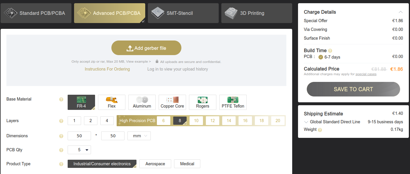
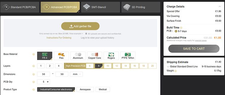
Webseite zur Konfiguration einer PCB-Bestellung
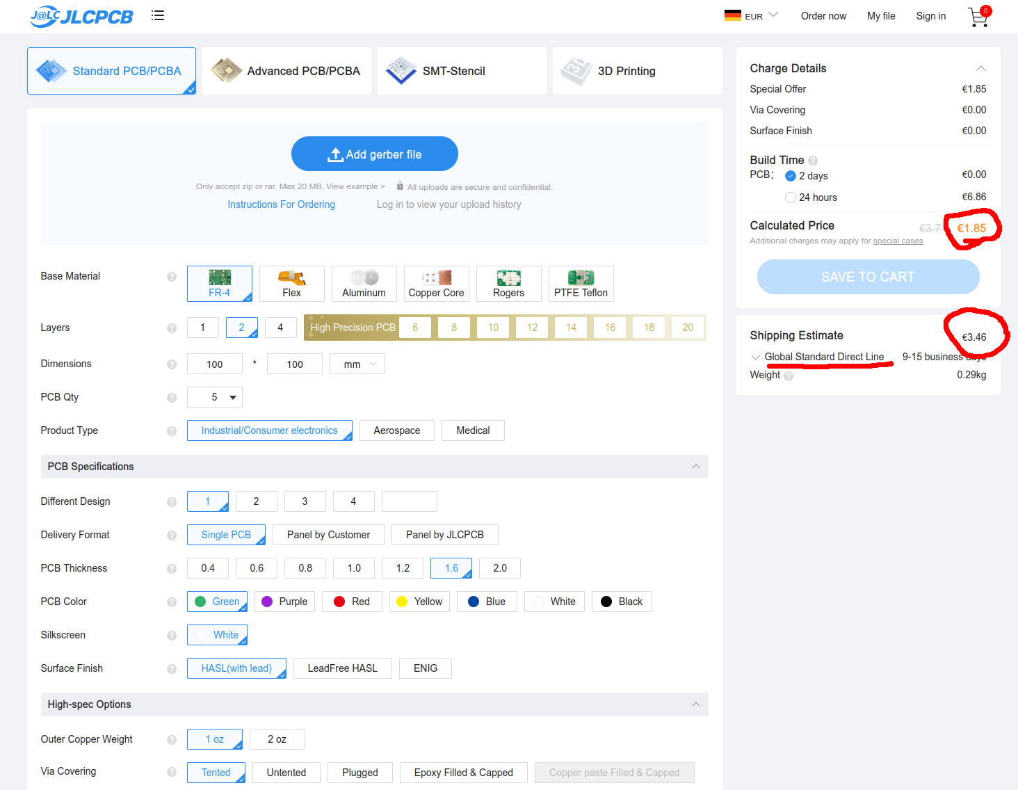
PCB/PCBA, Advanced PCB/PCBA, SMT-Stencil, 3D Printing, Add gerber file, Only accept zip or rar, Max 20 MB, View example, All uploads are secure and confidential, Instructions For Ordering, Log in to view your upload history, Charge Details, Special Offer, €1.86, Via Covering, €0.00, Surface Finish, €0.00
-
 Bild
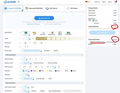
Bestellseite für PCB-Fertigung bei JLCPCB
€1.85 SAVE TO CART Shipping Estimate Global Standard Direct Line 9-15 business days Weight 0.29kg Base Material FR-4 Flex Aluminum Copper Core Rogers PTFE Teflon Layers 1 2 4 6 8 10 12 16 20 Dimensions 100 mm PCB Qty 5 PCB Specifications Different Design Delivery Format PCB Thickness PCB Color Silkscreen
-
Thread
ESp32 Multithreading
sollen, da delay scheinbar doch blockiert. https://www.esp32.com/viewtopic.php?t=8944#:~:text=This%20is%20vTaskDelay%20%28pdMS_TO_TICKS%20%2810%29%29%20a%20delay%20of,pdMS_TO_TICKS%20%28X%29%20which%20will%20do%20it%20for%20you.
timerCallback = [](void* arg) { TaskHandle_t task = static_cast<TaskHandle_t>(arg); BaseType_t xHigherPriorityTaskWoken = pdFALSE; vTaskNotifyGiveFromISR(task, &xHigherPriorityTaskWoken); if (xHigherPriorityTaskWoken) { portYIELD_FROM_ISR(); }
-
 Bild
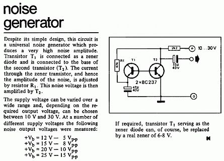
Schaltplan und Beschreibung eines Rauschgenerators
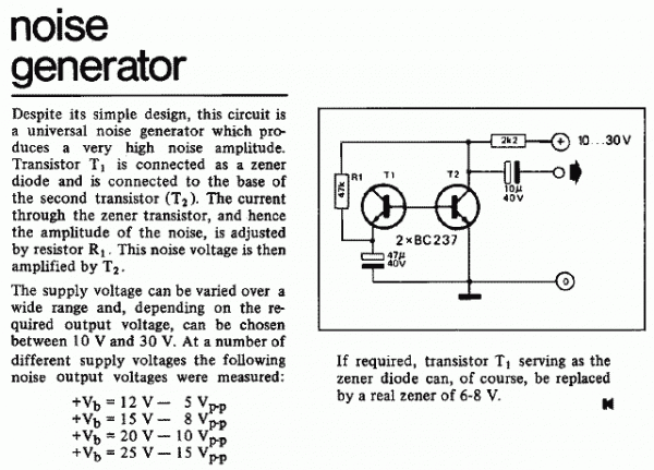
a very high noise amplitude. Transistor T1 is connected as a zener diode and is connected to the base of the second transistor (T2). The current through the zener transistor, and hence the amplitude of the noise, is adjusted by resistor R1. This noise voltage is then amplified by T2. The supply voltage
-
Thread
AES 128 CBC FIPS 197 entschlüsseln
F8B24F12F9D113F680BEE765FDE67EC0 IV 496A0392631400075050505050505050 Encrypted 98A78E0D71AA6358EEBD0B20BFDF99ED A2D22FA25314F3F1B84470898E495303 923770BA8DDA97C964F0EA6CE24F5650 C0A6CDF3DE37DE33FBFBEBACE4009BB0 D8EBA2CBE80433FF131328206020B1BF Dercrypted 2F2F0C1329730600026C942182046C81 218C0413754406008D0493132CFBFE12
java.security.InvalidAlgorithmParameterException: Wrong IV length: must be 16 bytes long at java.base/com.sun.crypto.provider.CipherCore.init(CipherCore.java:525) ``` Der IV ist richtig. Sonst würde miller-alex.de/WMbus ja meckern. Lasse ich beim IV die letzte Hälfte weg, dann bleibt noch C525030110105508
-
Thread
ein Stück Code funktioniert nicht
www.e-paper-display.com/download_list//downloadcategoryid=34&isMode=false.html // include library, include base class, make path known // DS18B20-Zubehörs................................................. #include <OneWire.h> #include <DallasTemperature.h> #define ONE_WIRE_BUS_1 13 #define ONE_WIRE_BUS
mich aber bei deinen anderen Threads zu dem Projekt schon gewundert: Warum packst du jeden DS18B20 an seinen eigenen OneWire Bus?
-
Thread
Auftragsarbeit open frame Netzteil
Transfer Mode Store and forward Mean Time Between Failure 100000 hour Network protocol IEEE802.3 (10Base-T) IEEE802.3u (100Base-TX) IEEE802.3ab (1000Base-TX) IEEE802.3z(1000Base-FX) IEEE802.3x (Flow control) PoE Protocol IEEE802.3af (15.4W) IEEE802.3at (30W) POE Pin 1/2 +, 3/6 - PoE Power Budget
EN55032) class A EMS: EN61000-4-2 (ESD)、 EN61000-4-4 (EFT) EN61000-4-5 (Surge) Network Medium 10Base-T : Cat3、4、5 or above UTP(≤100m) 100Base-TX : Cat5 or above UTP(≤100m) 1000Base-TX : Cat5 or above UTP(≤100m) Lighting Protection General Mode 6KV, Differential Mode 4KV, ESD 15KV Security Certificate
-
Thread
Umrechnungsskala erstellen
pressure-temperature-nomograph-interactive-tool ein interaktives Nomogramm http://onetuberadio.com/2016/06/20/making-your-own-nomograms-1946/ ein Artikel von 1946, wie man ein Nomogramm zeichnet https://deadreckonings.files.wordpress.com/2010/04/the_lost_art_of_nomography.pdf Artikel "The Lost Art of Nomography
Seiten auf ein Mal sein). 82.4 Ticks and Grids https://ftp.rrze.uni-erlangen.de/ctan/graphics/pgf/base/doc/pgfmanual.pdf
-
Thread
Bitte was bedeutet Uce und Ucb?
beide Abkürzzungen sind aus dem Englischen ce : collector - emitter cb : collector - base
Basetech BT 305. Noch ne Frage: Es steht 25 W drauf, das heißt doch eigentlich müßten 1,25 A rein (Bei 20 V), oder?