-
 Bild
Bild
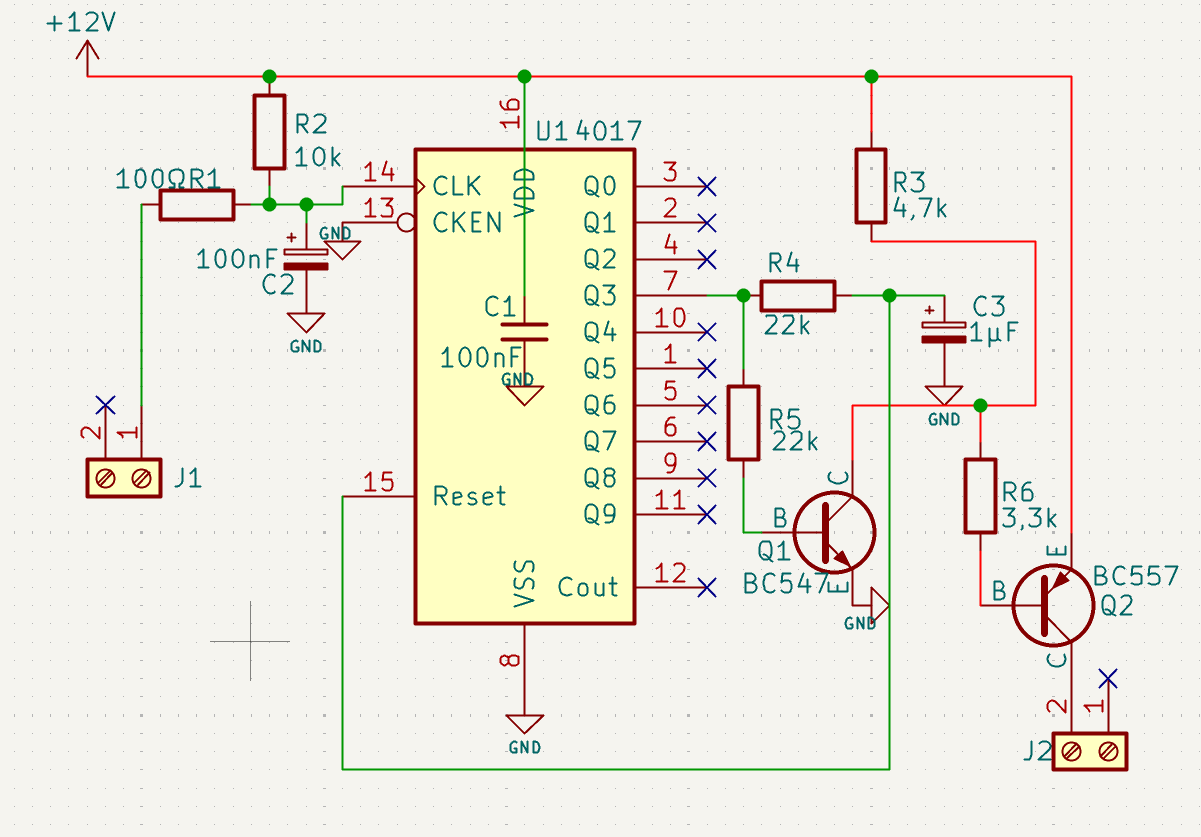
Schaltplan mit CD4017 Dezimalzähler
+12V R2 10k 14 CLK 13 CKEN 100R R1 100nF C2 GND U1 4017 16 VDD 3 Q0 2 Q1 X 7 Q2 R4 22k 4 Q3 1 Q4 5 Q5 R5 22k 6 Q6 9 Q7 10 Q8 11 Q9 12 Cout 15 Reset 8 GND C 1uF C3 GND B Q1 BC547 10 E BC557 Q2 2 C J2 J1 2 X
-
 Bild
Bild
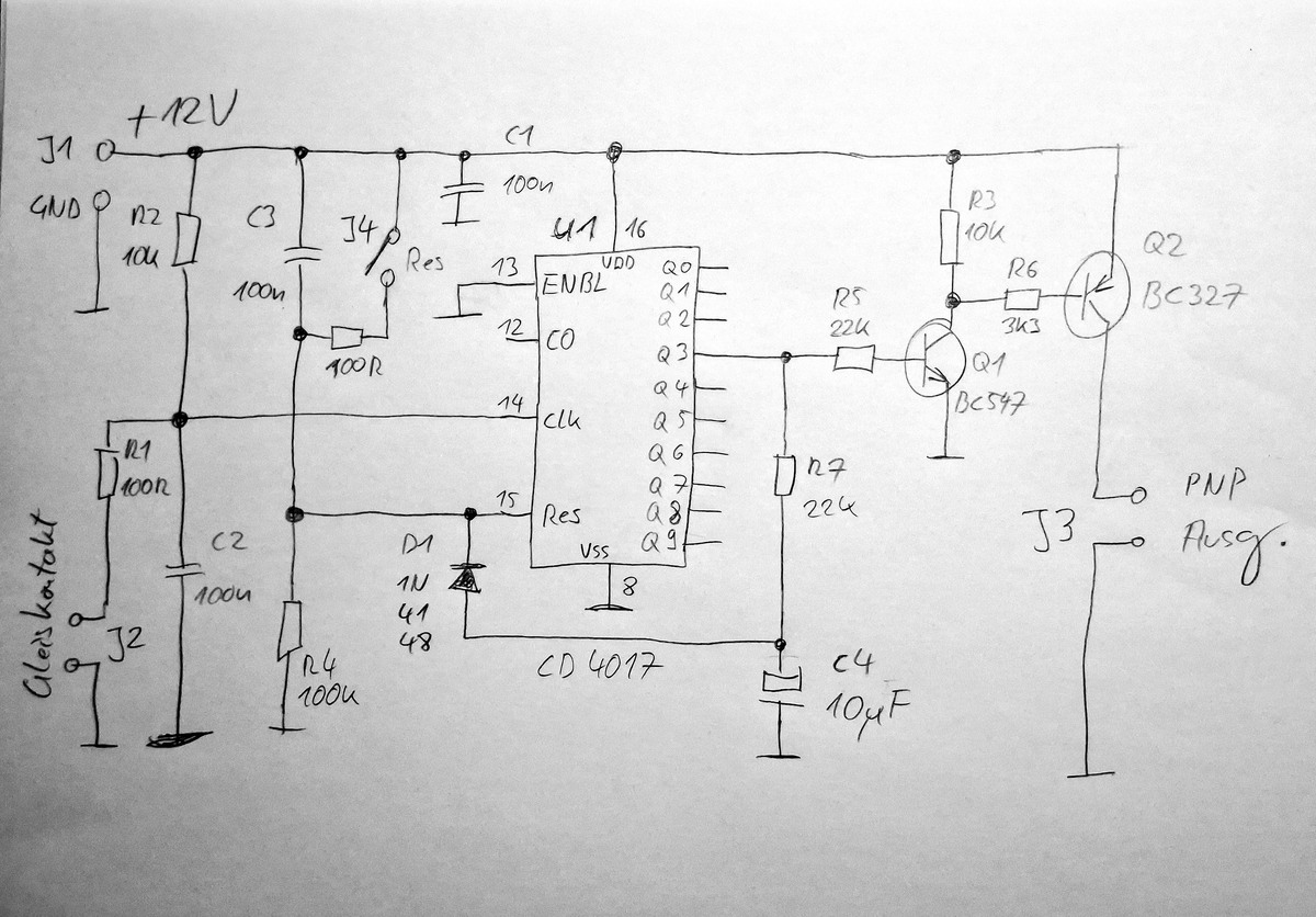
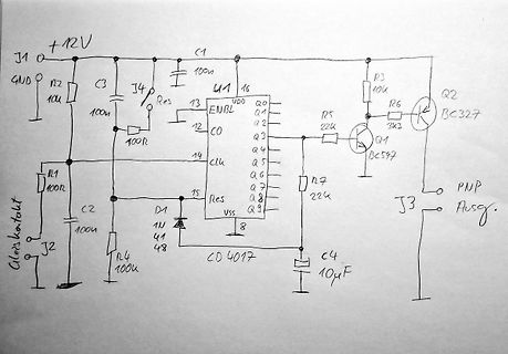
Handgezeichneter Schaltplan mit CD4017
+12V J1 GND R2 10u C3 100u J4 Res 13 U1 VDD 16 Q0 12 CO Q1 Q2 R3 10k R6 Q1 BC327 BC547 Q3 R5 22k Q4 Q5 Q6 R7 22k Q7 Q8 Q9 C4 10uF J3 Ausg. 14 Clk 15 Res 1 N 41 48 D1 VSS 8 CD4017 C2 100u R4 100u J2 Alert kontakt
-
 Bild
Bild
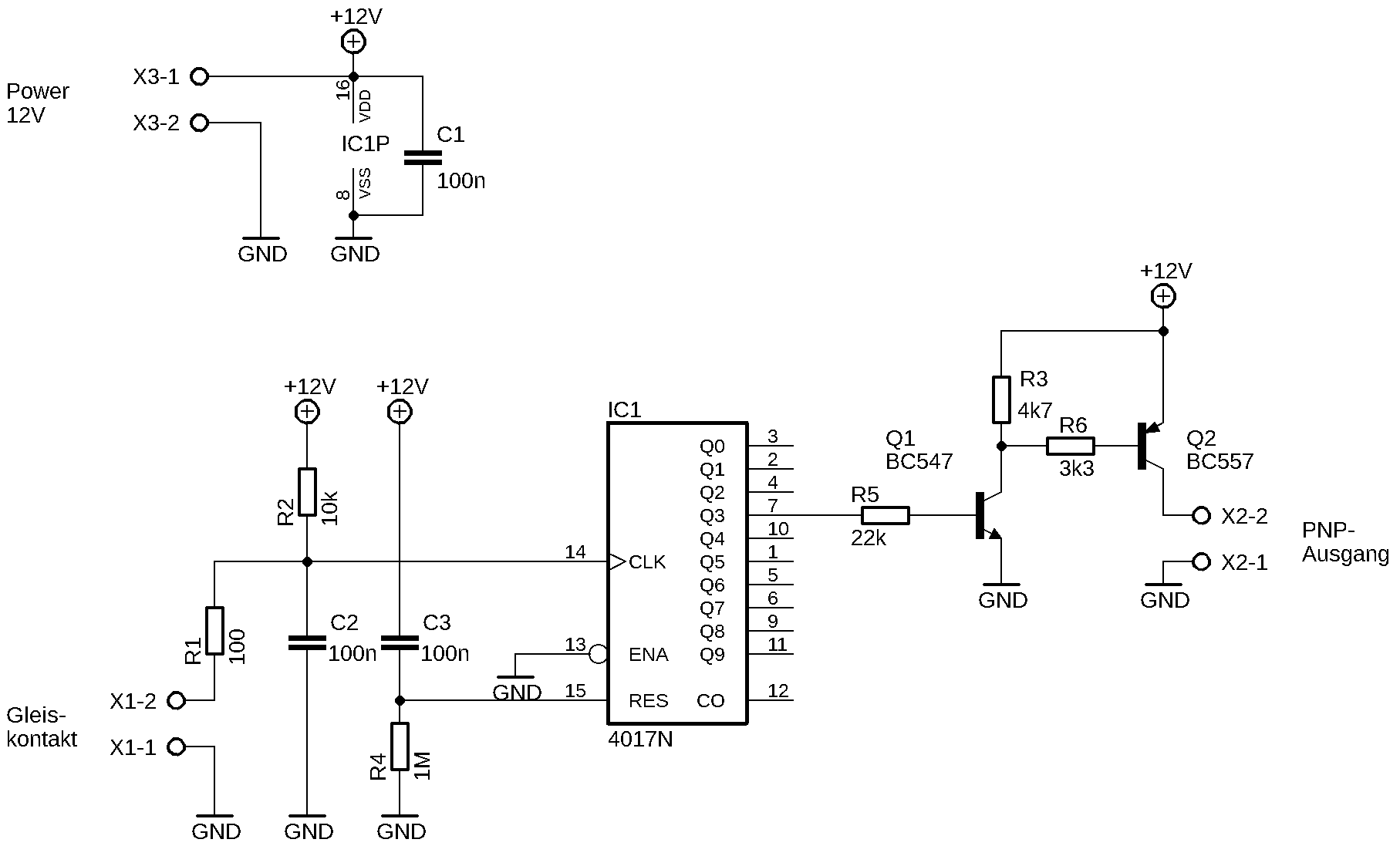
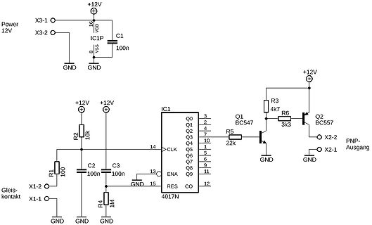
Schaltplan mit 4017N Zähler und PNP-Ausgang
Power 12V X3-1 X3-2 +12V 16 VDD C1 8 VSS 100n GND GND IC1P C2 R1 R2 10k 100 C3 100n 1M R4 X1-2 X1-1 GND GND IC1 4017N 14 CLK 13 GND 15 ENA 12 CO Q0 Q1 Q2 Q3 Q4 Q5 Q6 Q7 Q8 Q9 R5 22k R3 4k7 R6 3k3 +12V Q2 BC557 X2-2 X2-1 PNP-Ausgang GND
-
 Bild
Bild
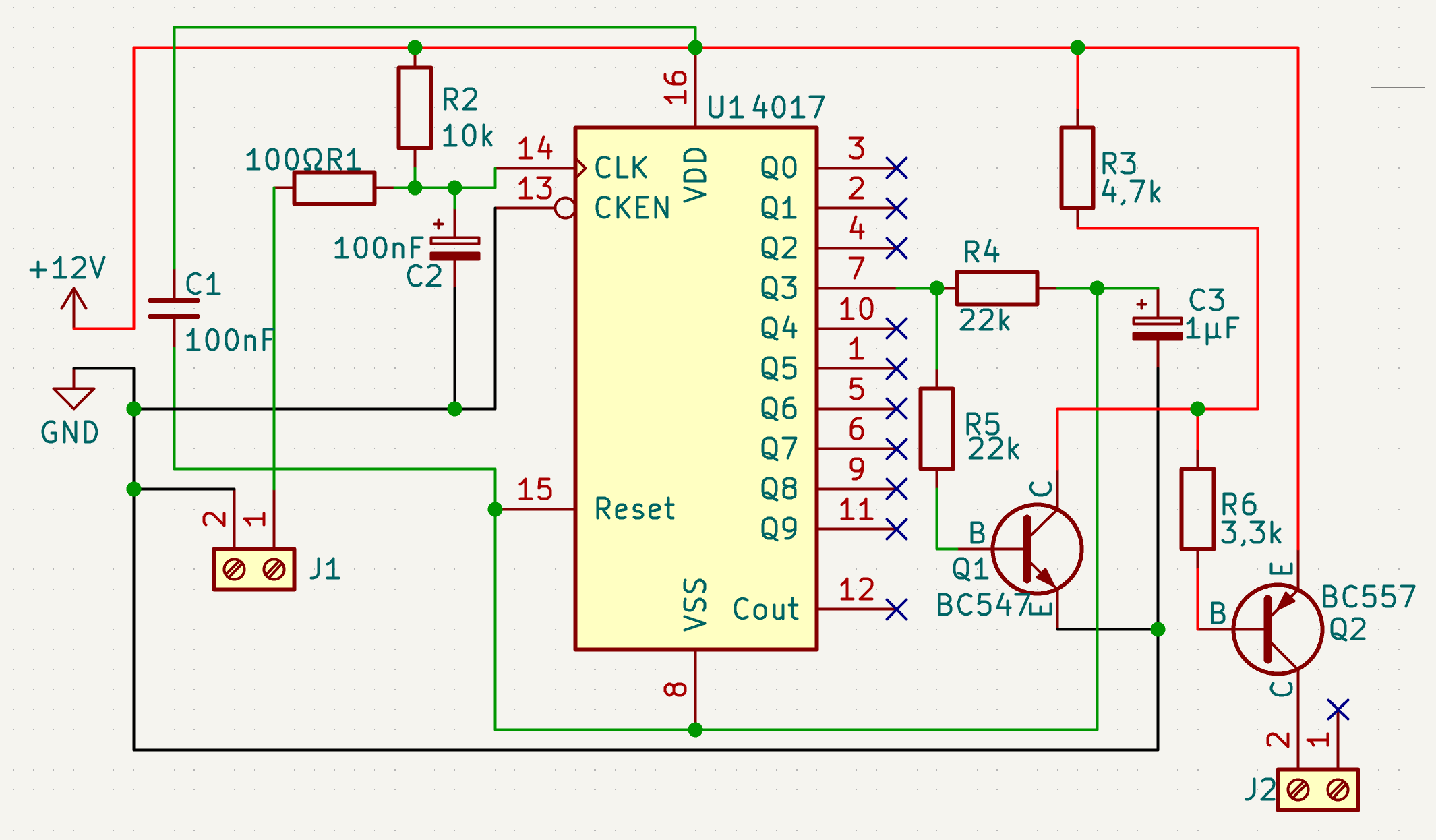
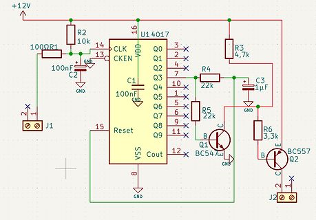
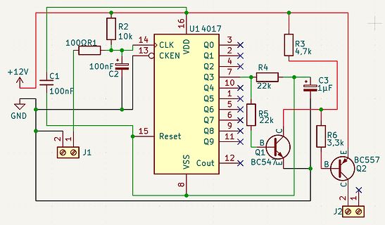
Schaltplan mit CD4017 Zähler und Transistoren
+12V GND C1 100nF R1 100R R2 10k C2 100nF U1 4017 16 13 3 2 4 7 10 1 5 6 9 11 12 15 8 CLK CKEN VDD Q0 Q1 Q2 Q3 Q4 Q5 Q6 Q7 Q8 Q9 Reset VSS Cout R3 4,7k R4 22k R5 22k C3 1µF Q1 BC547w B C R6 3,3k Q2 BC557 B C J1
-
 Bild
Bild
Digitalmultimeter mit Messspitzen
2000M 200mV V 2V 200V 750mV 10MHz 2mA A 2mA 200mA 20A 20A 200mA MAX 20A FUSED MAX 20A EVERY 15 MIN. C uF nH mH mA

-
 Bild
Bild
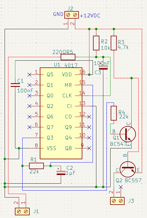
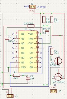
Schaltplan mit CD4017 und Transistoren
100nF U1 4017 16 VDD 15 MR 14 CLK 13 CI 12 Q9 11 Q4 10 Q8 9 Q9 8 VSS 7 Q3 6 Q7 5 Q6 4 Q2 3 Q0 2 Q1 1 C1 100nF 220R5 R1 22k C2 1μF + Q1 BC547 B C R4 22k B Q2 BC557 C E 2 J3 1 J1
-
Thread
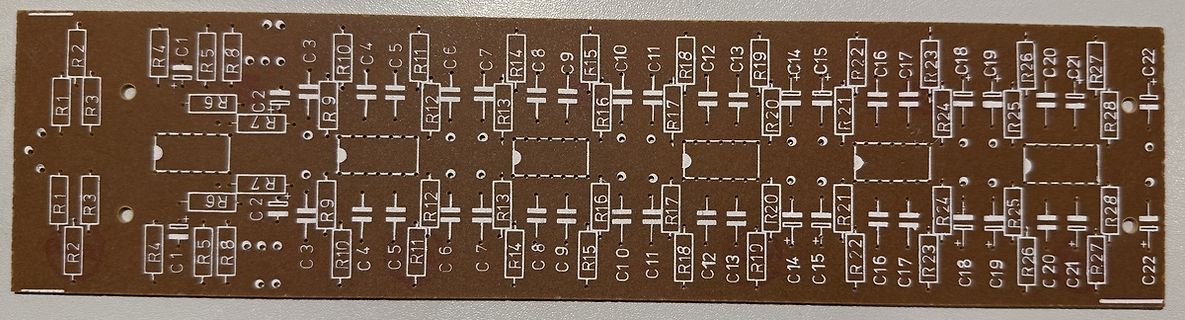
10 Kanal Stereo Equalizer - Bestückungsplan
/unterhalb von R7/C2 die ich noch entschlüsseln muss.
/unterhalb von R7/C2 die ich noch entschlüsseln muss.
-
 Bild
Bild
Leiterplatten-Layout ohne Bestückung
R1 R2 R3 R4 C1 R5 R6 C2 R7 R9 R10 C3 C4 C5 C6 R7 R8 R9 R10 R1 R12 R13 R14 C7 C8 C9 C10 C1 R15 R16 R17 R18 R19 R20 R21 R2 R23 R24 R25 R26 R27 R28 C12 C13 C14 C15 C16 C17 C18 C19 C20 C21 C2
-
Thread
Siemens Kühl-Gefrierkomi vereist im Kühlteil
Kompressor z.B. wegen eines defekten Thermostaten ständig läuft und das Kühlfach dann nicht unter 0°C kommt, könnte es schon sein. Vielleicht auch nicht Verlust, sondern einfach zu wenig drin. Kann die Abwärme hinten gut abziehen?
die Temperatur im Gefrierteil und wie soll die laut Anleitung > sein? Sie soll "mindestens" -18°C betragen. Hier geht die total unterbelichtete BSH-Anleitung zur Temperatur los: https://www.bedienungsanleitu.ng/siemens/ki34vv22ff/anleitung?p=11 Nächste Seite: "Gefrierraum Die Temperatur
-
 Bild
Bild
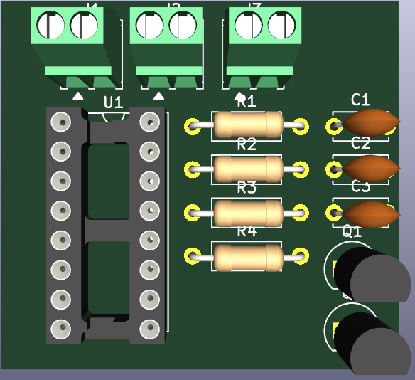
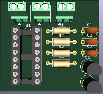
3D-CAD-Modell einer Leiterplatte mit Bauteilen
U1 R1 C1 R2 C2 R3 C3 R4 Q1
-
 Bild
Bild
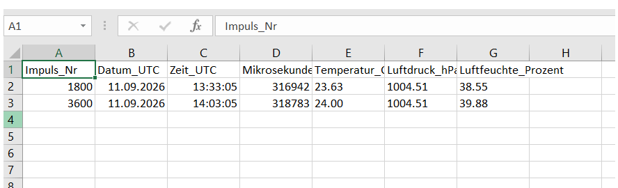
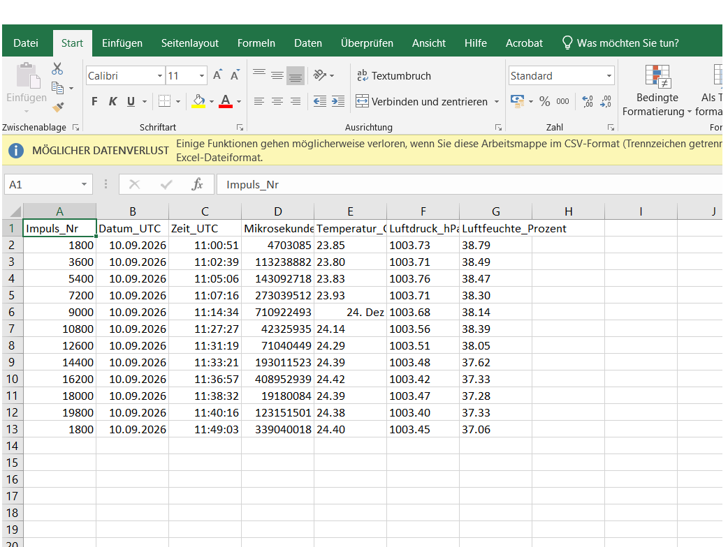
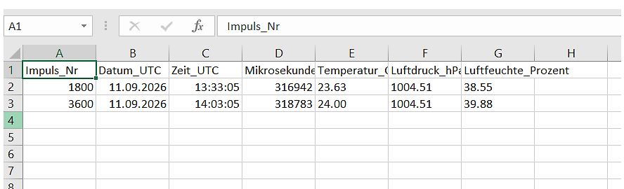
Excel-Tabelle mit Messdaten
A1 Impuls_Nr Datum_UTC Zeit_UTC Mikrosekunde Temperatur_C Luftdruck_hPa Luftfeuchte_Prozent 180 1.09.2026 13:3:05 316942 23.63 104.51 38.55 360 11.09.2026 14:03:05 318783 24.0 104.51 39.8
-
 Bild
Bild
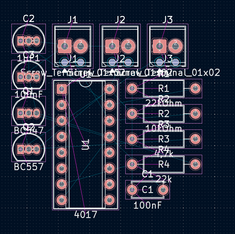
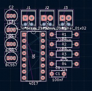
Bestückungsdruck einer Leiterplatte
C2 J1 J2 J3 P1 J1 J2 J3 10nF R1 R2 22 Ohm R2 10 Ohm R3 R3 4,7k R4 R4 2k C1 10nF C2 47 BC547 BC57 U1 4017
-
 Bild
Bild
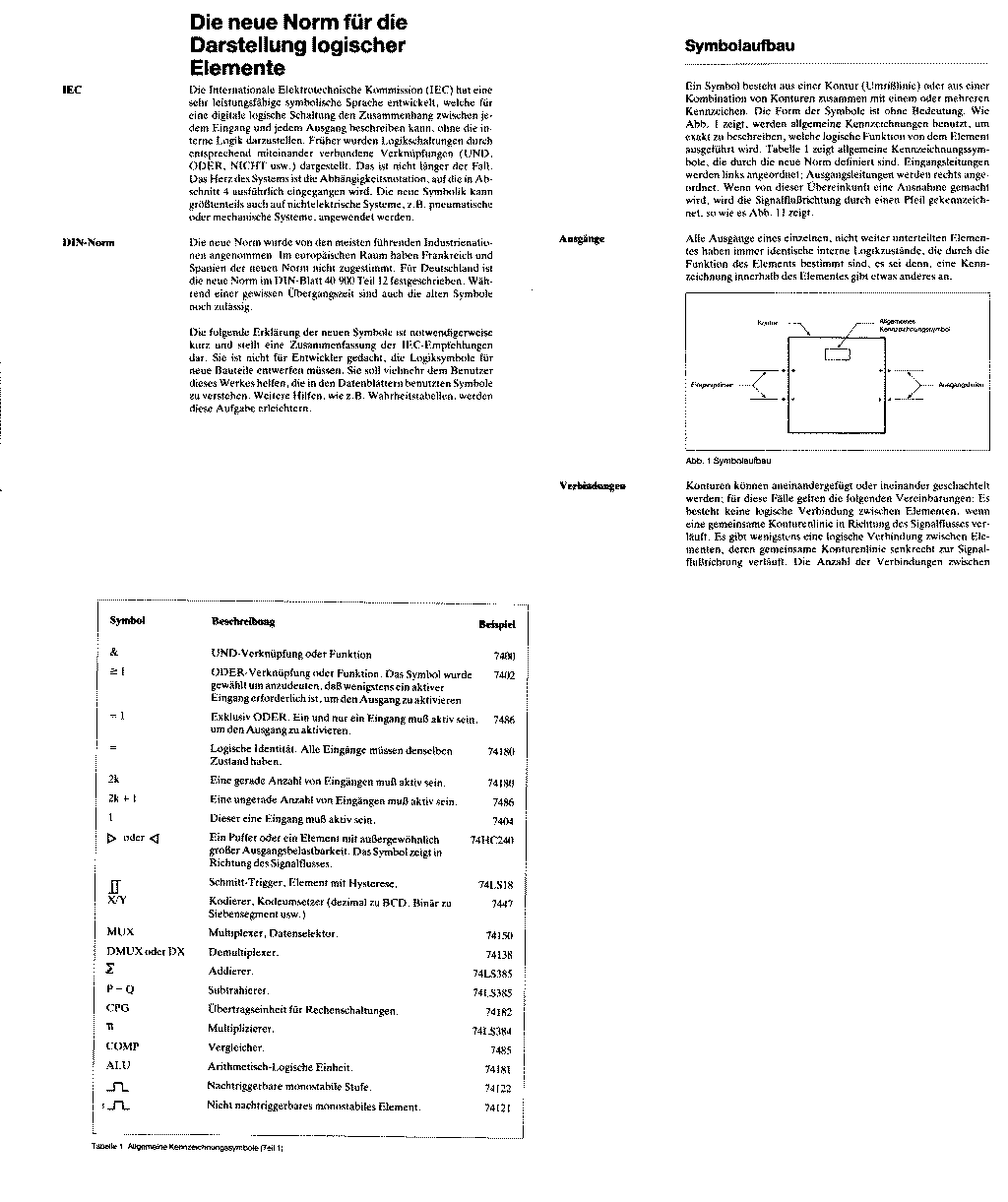
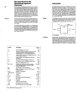
Erklärung der IEC-Logiksymbole und Tabelle
Anzahl von Eingängen aktiv sein 74180 Eine ungerade Anzahl von Eingängen aktiv sein 7404 oder > Oder 741C240 Π N/V Kodierer, Demultiplexer (dezimal zu BCD, Binär zu Sequenz usw.) 74LS38 MUX Multiplexer, Datenselektor 74LS150 Σ Addierer 74LS385 P - Q Subtrahierer 74LS385 CPG Übertragungseinheit für Rechenaufgaben
-
 Bild
Bild
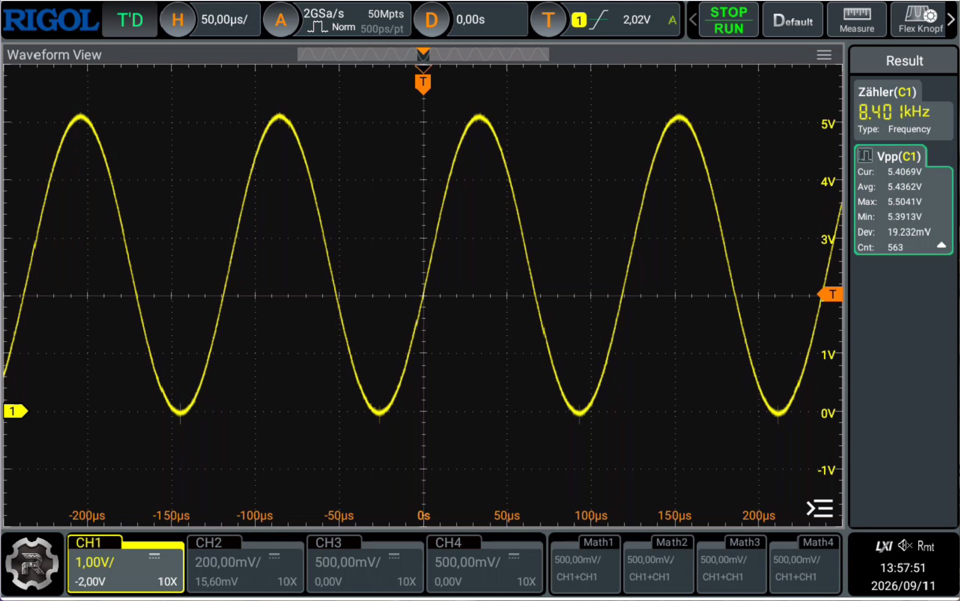
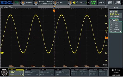
Oszilloskop-Screenshot einer Sinuswelle
RIGOL T'D 50,0µs/ 2GSa/s 50Mpts D 0,0s T 1 2,02V A T Waveform View Result Zähler(C1) 8.40 kHz Type: Frequency Vpp(C1) Cur: 5.4069V Avg: 5.4362V Max: 5.5041V Min: 5.3913V Dev: 19.232mV Cnt: 563 1V 0V -1V 1 1,0V/ -2,0V 10X CH1 CH2 20,00µs/ 15,60V 10X CH3 50,0mV/ 0,0V 10X CH4 50,0mV/
-
 Bild
Bild
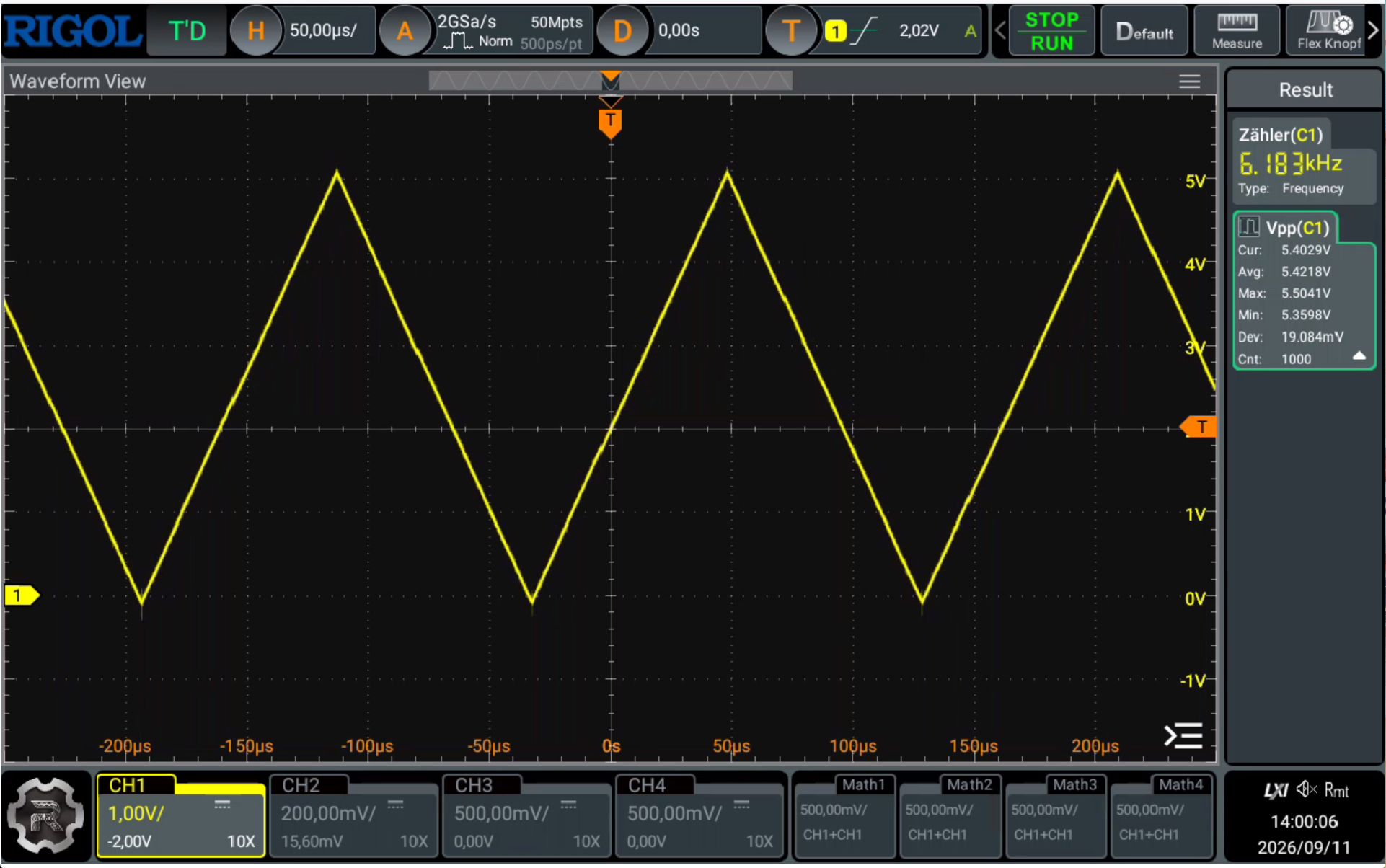
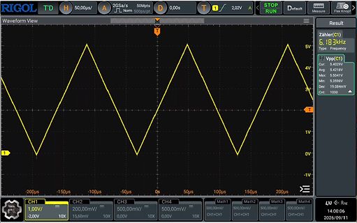
Oszilloskop-Screenshot eines Dreiecksignals
T'D 50,0µs/ 2GSa/s 50Mpts D 0,0s A T 2,02V STOP RUN Default Measure Flex Knob Waveform View Zähler(C1) 6.183kHz Type: Frequency Cur: 5.4029V Max: 5.5041V Avg: 5.4218V Min: 5.3598V Dev: 19.084mV Cnt: 10 4V 1V 0V -1V T CH1 1,0V/ -2,0V 10X CH2 20mV/ 15,60mV 10X CH3 50mV/ 0,0V 10X CH4 50mV/ 0,0V 10X Math3
-
 Bild
Bild
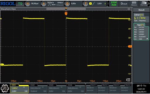
Oszilloskop-Screenshot eines Rechtecksignals
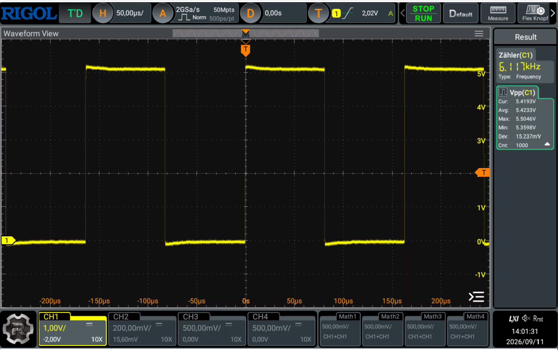
50,00µs/ 2GSa/s 50Mpts D 0,0s T 1 2,02V STOP RUN Default Measure Flex Knob Waveform View T Zähler(C1) 6,17kHz 5V Vpp(C1) Cur: 5,423V Max: 5,504V Avg: 5,423V Min: 5,359V Dev: 15,237mV Cnt: 100 4V 1V 0V -1V CH1 1,0V/ -2,0V 10X CH2 20,0mV/ 10X CH3 50,0mV/ 10X CH4 500,0mV/ 10X Math1 CH1+CH1 Math2 CH1+CH1
-
 Bild
Bild
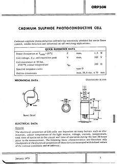
Datenblatt einer Cadmium-Sulphid-Fotowiderstands-Zelle
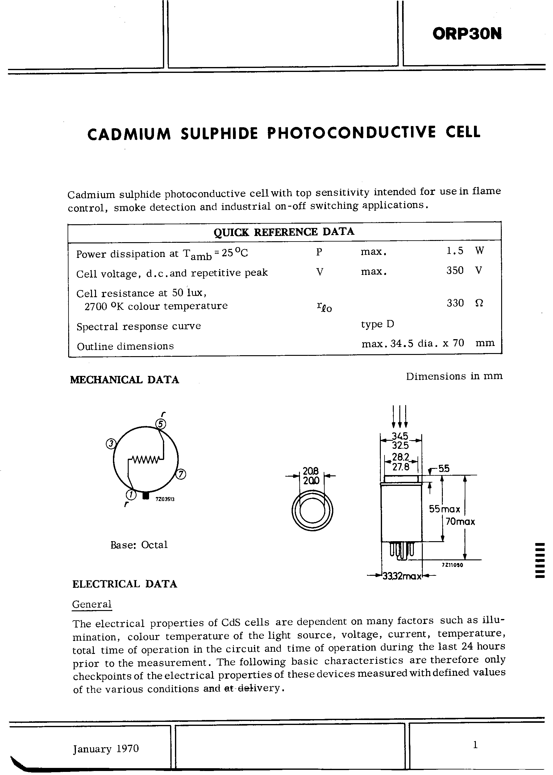
ORP30N CADMIUM SULPHIDE PHOTOCONDUCTIVE CELL QUICK REFERENCE DATA Power dissipation at Tamb = 25°C P max. 1.5 W Cell voltage, d.c. and repetitive peak V max. 350 V Cell resistance at 50 lux Rfo 30 Ω 270 °K colour temperature type D Spectral response curve Outline dimensions max. 34.5 dia. x 70 mm
-
Thread
Werden statische lokale Arrays vom XC32 compiler automatisch beim Programmstart auf 0 initialisiert
Messwertes der geschrieben wird int Ergebnis,Schleife; // Der Rest code kommt später [/c]
Normalerweise schon (Liegen im BSS). Aber schreib einfach [c] static int Puffer[MaxNummer][MaxWerte] = {0}; static int Zeiger[MaxNummer] = {0}; [/c] Wenn dir die Initialisierung wichtig ist. Wenn der Compiler das eh gemacht hätte, ist das kein zusätzlicher
-
Thread
DIY Niederspannungs Leitungsfinder
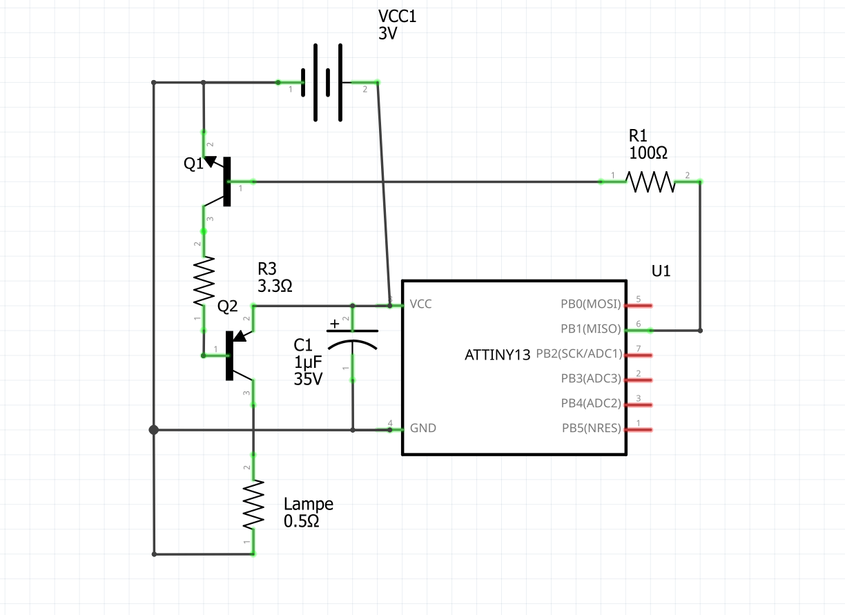
kHz erkannt wird. Daraufhin habe ich ein Schaltung mit einem ATtiny13V für 2-5 VDC gebaut. Der uC gibt ein 14,5kHz signal aus, das durch Transistoren auf die Leitung gegeben wird. Das geht im akkubetrieb oder auf schon bereits spannungsführenden Leitungen. Als Optische Anzeige und einstellbare Signalstärke
fast identisch (Hier sollte mit einem Oszilloskop die Frequenz fein über die Widerstände R1/R3 oder C1 eingestellt werden). Im nachhinein wäre es wahrscheinlich einfacher und günstiger gewesen die alte Schaltung mit einem Linearen Spannungsregler vor dem ATtiny auszustatten, damit dieser auch für 12V
-
 Bild
Bild
Schaltplan mit NE55 Timer und MOSFET
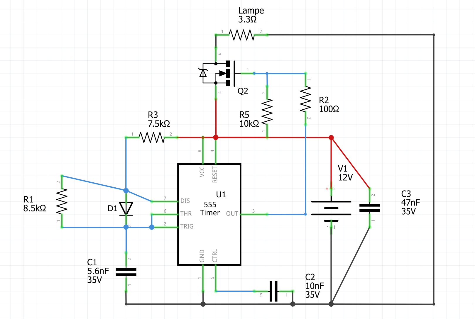
Lampe 3.3Ω, Q2, R2 10Ω, R5 10kΩ, R3 7.5kΩ, R1 8.5kΩ, D1, C1 5.6nF 35V, C2 10nF 35V, C3 47nF 35V, U1 5 Timer, V1 12V
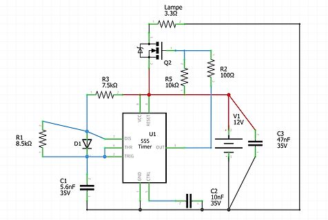
-
 Bild
Bild
Schaltplan mit ATtiny13 und Transistoren
Q1 R1 10Ω U1 PB0(MOSI) 5 PB1(MISO) 6 PB2(SCK/ADC1) 7 PB3(ADC3) 2 PB4(ADC2) 4 PB5(NRES) 1 R3 3.3Ω Q2 C1 1µF 35V Lampe 0.5Ω GND
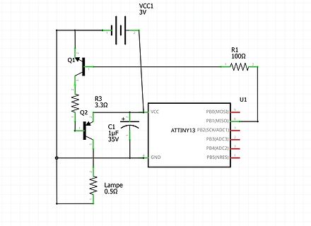
-
 Bild
Bild
Schaltplan und Elektronikbauteile in einem Karton
DKE38-0c.jpg
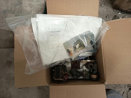
-
 Bild
Bild
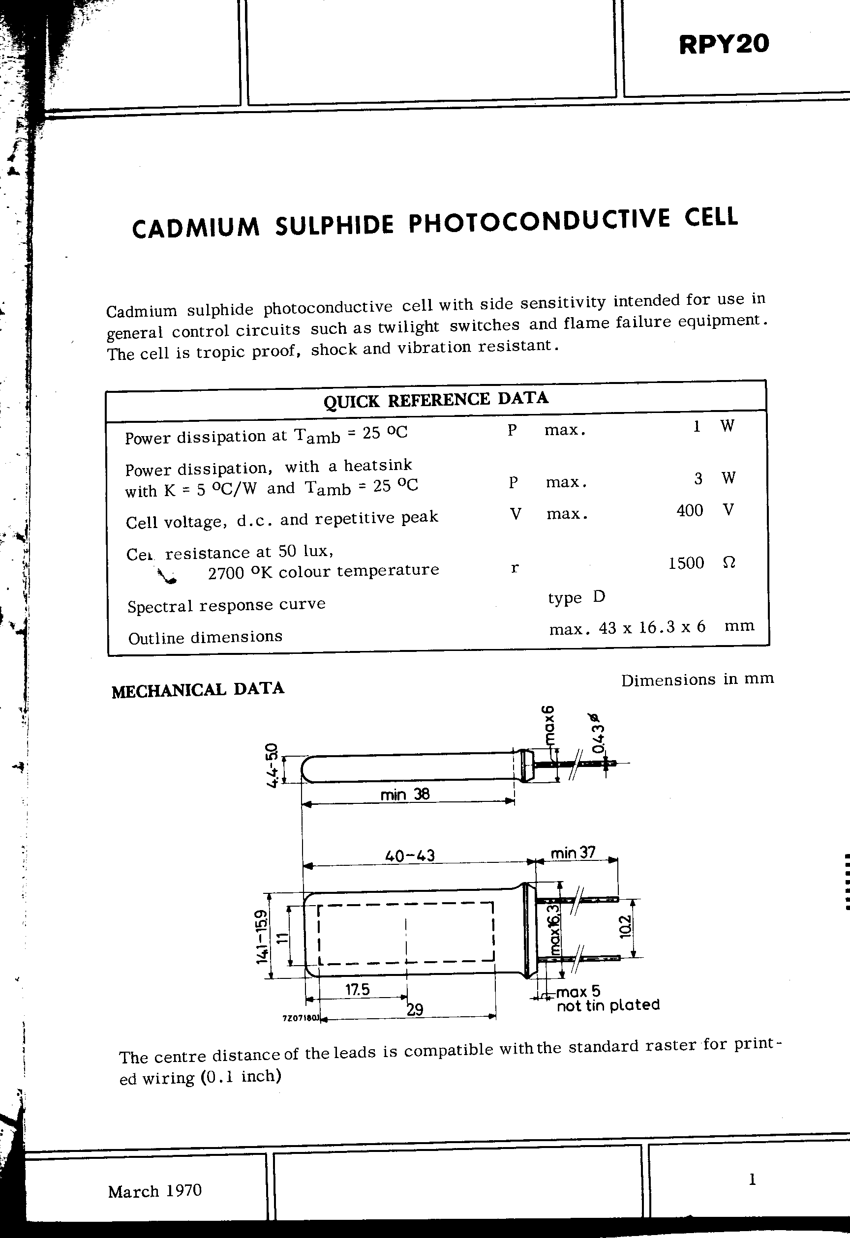
Datenblatt einer Cadmium-Sulphid-Fotozelle
RPY20 CADMIUM SULPHIDE PHOTOCONDUCTIVE CELL QUICK REFERENCE DATA Power dissipation at Tamb = 25 °C P max. 1 W Power dissipation, with a heatsink with K = 5 °C/W and Tamb = 25 °C P max. 3 W Cell voltage, d.c. and repetitive peak V max. 40 V Cell resistance at 50 lux r 150 Ω 270 °K colour temperature
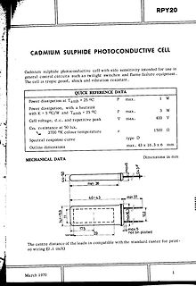
-
Thread
Bauteilidentifikation: Schaltregler, Buck, SOT-23-6, Vin = 25.2V, Vout = 5.0V (Adj), MC: A2CZ
aber nur bis Vin 24V https://www.m3tekic.com/upload/files/M3tek%E9%80%89%E5%9E%8B%E6%89%8B%E5%86%8C_2025Q1.pdf MT3771N(A) ✅ 0,8 24 V ⭐⭐⭐⭐ MP1470 / LYF98102 ✅ 0,8 16/18 V ❌ AP62150 ✅ 0,8 18 V ❌ Alle anderen Vorschläge haben entweder Vref 0,6V oder ein anderes Pinout.
-
Thread
HP N54L ersetzen
Beitrag #8094348: > Was habt ihr so im Hauswirtschaftsraum rumservern? * Supermicro_X11SDV-4C-TP8F, Intel(R) Xeon(R) D-2123IT, 64GB ECC DDR4 * 128G MSATA Boot SSD, 2TB WD NVME für Container usw * 4* 8TB TOSHIBA HDWG480 SATA Disks * 10G SFP+ und DAC zum Switch * TrueNAS 25.10.7 fchk
-
Artikel
STM32
verfügbar. Selber zusammenstellen. Man nehme...: Eine Entwicklungsumgebung nach Wahl: Eclipse mit C/C++ Development Tooling und Eclipse Embedded CDT(Linux, Windows) System Workbench for STM32 basiert auf Eclipse Netbeans mit GDBserver-Plugin (Linux, Windows) KDevelop (Linux, Windows) Geany (Linux, Windows) Oder ein einfacher Texteditor Einen C,C++ Compiler: Eine der GCC-Binärdistributionen, siehe auch GCC (je nach Distribution Linux, Windows) Programmiersoftware zum Flashen des Target: OpenOCD unterstützt viele Debug/Programmier-Adapter (Linux
-
Thread
Hilfe: Reparatur Uhrenradio Furntronic FCR-20
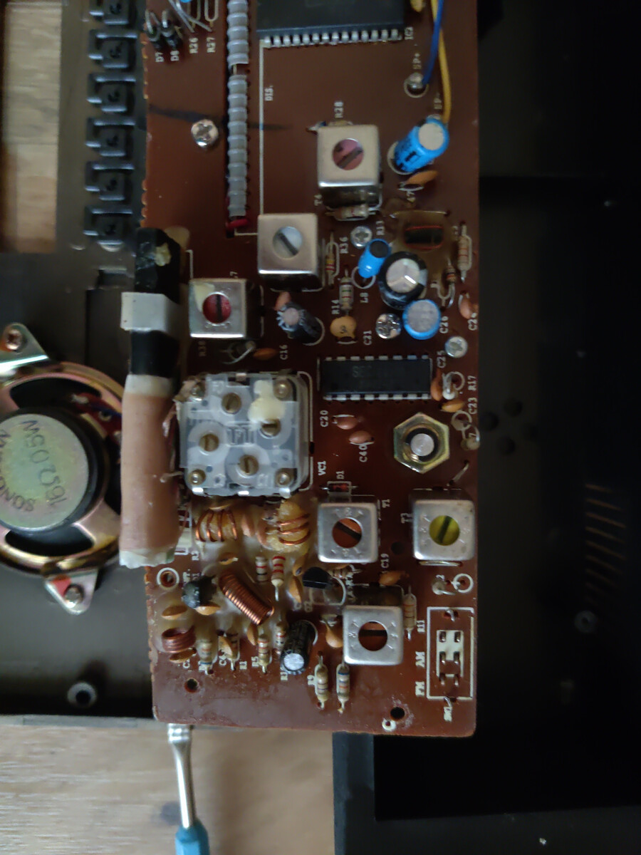
Leider keine Pläne hinterlegt. https://www.radiomuseum.org/r/plast_furntronic_fcr_20.html#c Auf dem Foto (317) erkenne ich nicht die Bezeichnung des Uhren-ICs (28-Poler). Für Fehlersuche eventuell wichtig. ciao gustav
www.homemade-circuits.com/simple-digital-clock-circuit-explained/ Das entspricht im o.g. Schaltplan dann C2 (470µF). Ersetze diesen.
-
 Bild
Bild
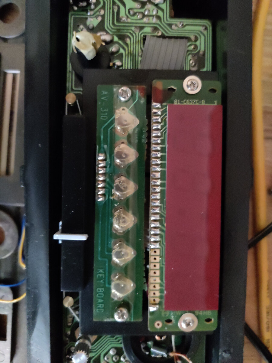
Innenansicht einer Leiterplatte mit Tastaturmodul
AV-310 KEYBOARD 01-C637C-B 1 94HB
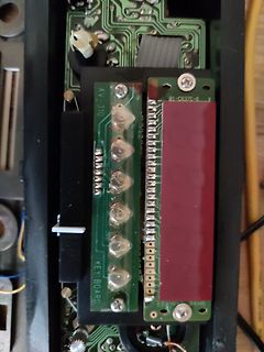
-
 Bild
Bild
-
 Bild
Bild
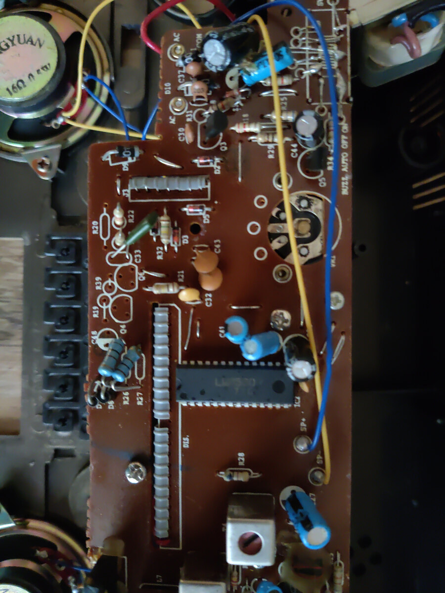
Foto einer bestückten Leiterplatte mit elektronischen Bauteilen
GYUAN 160, D10, C10, C1, R29, C44, R34, AUTO OFF, R20, C33, C43, R21, C32, C48, Q4, R39, R36, R35, C45, R27, R26, D15, R28, R25
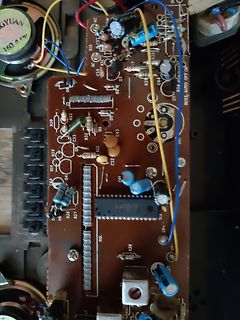
-
 Bild
Bild
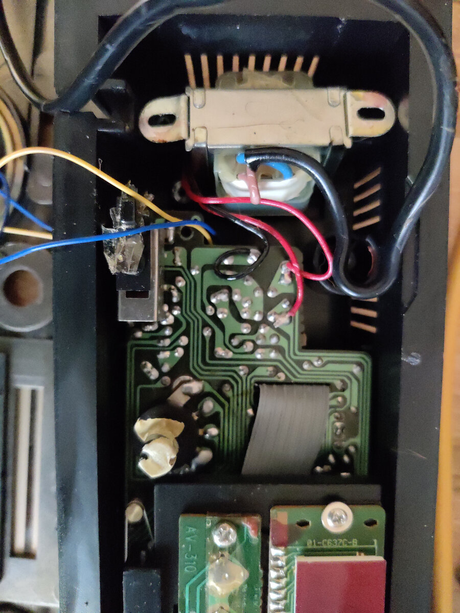
Leiterplatte mit elektronischen Bauteilen und Transformator
D7, R24, R27, D15, R28, R36, R1, C1, C12, C13, C14, C15, C16, C17, C18, C19, C20, C21, C2, C23, C24, C25, C26, C27, C28, C29, C30, C31, C32, C3, C34, C35, C36, C37, C38, C39, C40, C41, C42, C43, C4, C45, C46, C47, C48, C49, C50, C51, C52, C53, C54, C5, C56, C57, C58, C59, C60, C61, C62, C63, C64, C65, C6, C67, C68, C69, C70, C71, C72, C73, C74, C75, C76, C7, C78, C79, C80, C81, C82, C83, C84, C85, C86, C87, C8, C89, C90, C91, C92,
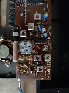
-
 Bild
Bild
Datenblatt einer Cadmium-Sulphid-Photozelle
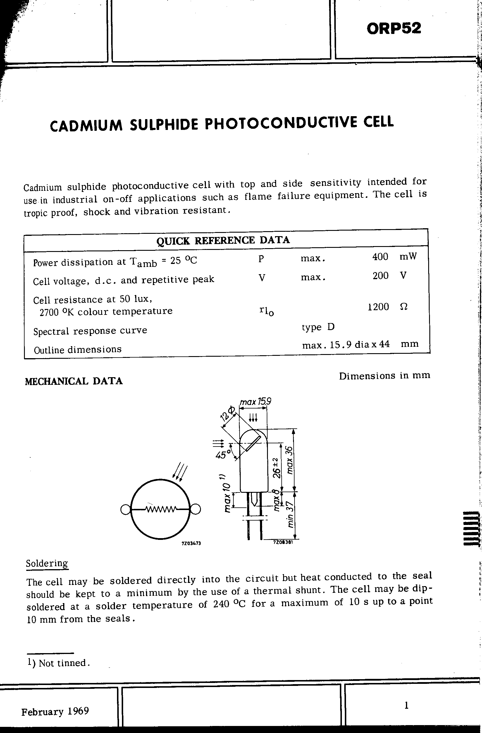
ORP52 CADMIUM SULPHIDE PHOTOCONDUCTIVE CELL QUICK REFERENCE DATA Power dissipation at Tamb = 25 °C P max. 40 mW Cell voltage, d.c. and repetitive peak V max. 20 V Cell resistance at 50 lux r10 120 Ω 270 K colour temperature type D Spectral response curve max. 15.9 dia x 44 mm Outline dimensions Dimensions
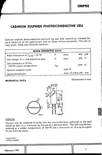
-
 Bild
Bild
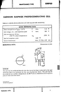
Datenblatt einer Cadmium-Sulphid-Photoconductive Cell
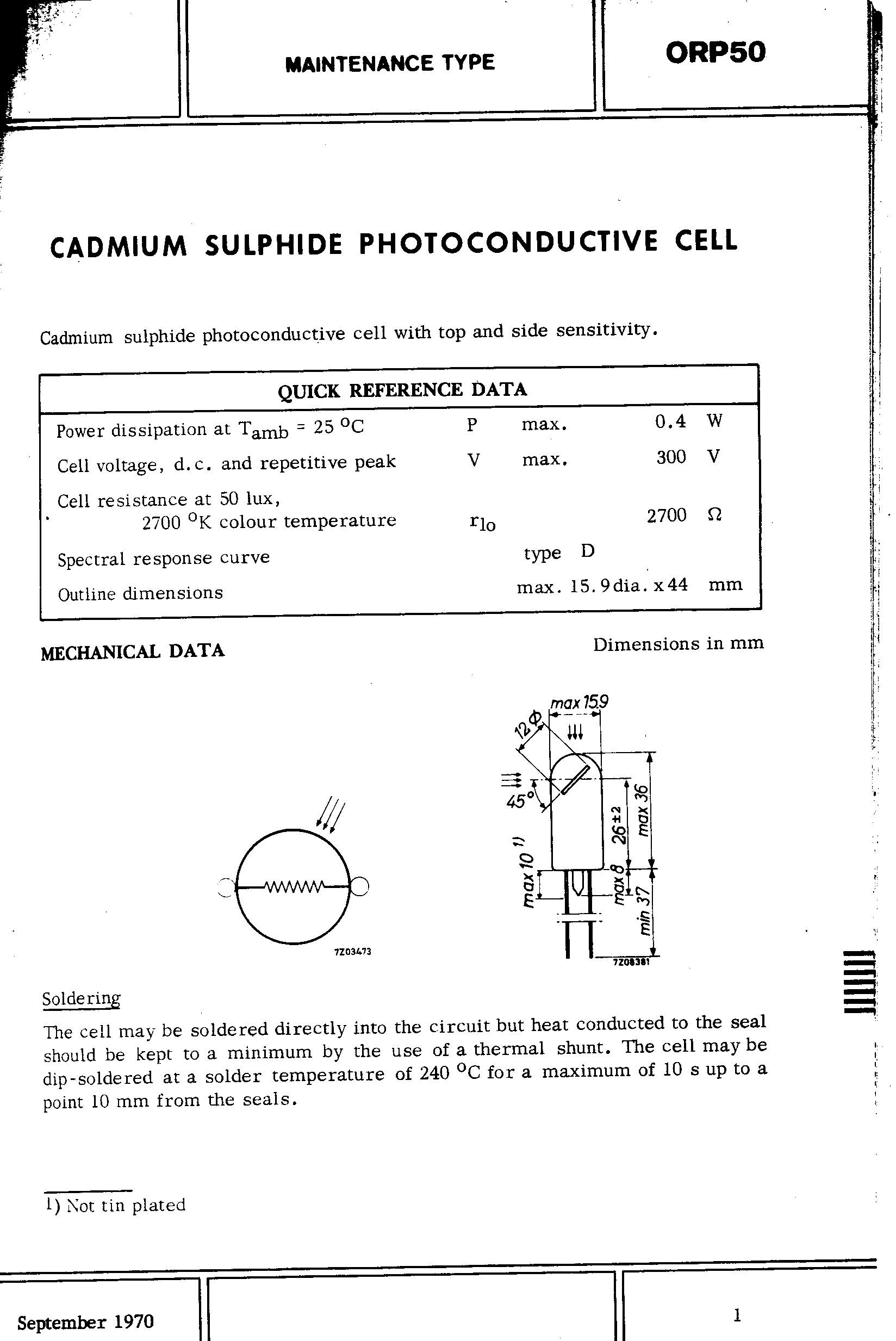
TYPE ORP50 CADMIUM SULPHIDE PHOTOCONDUCTIVE CELL QUICK REFERENCE DATA Power dissipation at Tamb = 25 °C P max. 0.4 W Cell voltage, d.c. and repetitive peak V max. 30 V Cell resistance at 50 lux, 270 °K colour temperature rlo 2700 Ω Spectral response curve type D Outline dimensions max. 15.9 dia. x 4 mm
-
 Bild
Bild
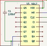
Ausschnitt eines Schaltplans mit IC 4D17
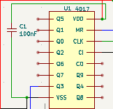
U1 4D17 C1 10nF Q5 VDD Q1 MR Q0 CLK Q2 CI Q6 C0 Q7 Q9 Q3 Q4 VSS Q8
-
 Bild
Bild
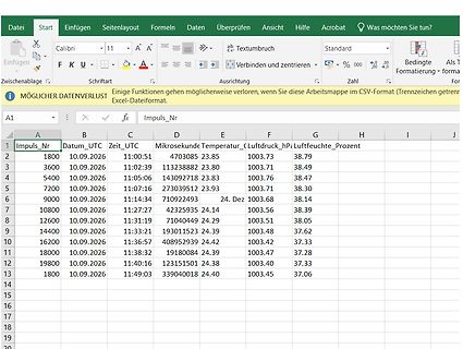
Excel-Tabelle mit Messdaten
Formeln Daten Überprüfen Ansicht Hilfe Acrobat Impuls_Nr Datum_UTC Zeit_UTC Mikrosekunde Temperatur_C Luftdruck_hPa Luftfeuchte_Prozent 1800 10.09.2026 1:0:51 4703085 23.85 103.73 38.79 360 10.09.2026 1:02:39 132382 23.80 103.71 38.49 540 10.09.2026 1:05:06 14039213 23.83 103.76 38.47 720 10.09.2026
-
Thread
[S] SEGGER J-Link EDU (ab V10) oder EDU Mini
J-Link EDU (ab Hardware-Revision V10) - Ein J-Link EDU Mini (egal ob Version mit Micro-USB oder Type-C / V2) Ideal wäre es natürlich, wenn das passende Flachbandkabel direkt mit dabei ist. Das Gerät allein ohne weiteres Zubehör ist mir aber genauso recht. Falls jemand noch ein funktionierendes Exemplar
-
 Bild
Bild
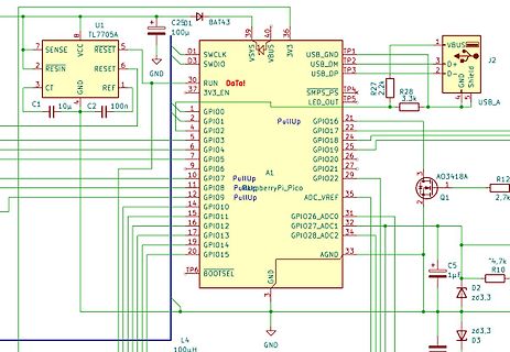
Schaltplan eines Raspberry Pi Pico Projekts
U1 TL7705A, C25D1 10uF, BAT43, 3V3, USB_GND, TP1, TP2, USB_DM, USB_DP, TP3, R27 2.2k, R28 3.3k, J2, USB_A, AO3418A, Q1, R12 2.7k, C5 1uF, D2 zd3,3, R10 4,7k, AGND, GPIO28_ADC2, GPIO27_ADC1, GPIO26_ADC0, A1 RaspberryPiPico
-
Thread
[S] Jemanden, der mir einen alten Papst Außenläufer Motor neu wickeln kann
ich das! Dieter, die gesuchten Motoren sehen so aus: https://www.cjm-audio.de/phono/papst-au%C3%9Fenl%C3%A4ufermotoren/
-
Thread
DVD/BR Laufwerk aus Laptop, externes Gehäuse gesucht
Mist, ich hatte dieses Gehäuse bestellt: https://www.amazon.de/Externes-Laufwerksgeh%C3%A4use-Herausnehmbares-Laufwerke-RW-Laufwerk/dp/B0B2XYYW5C Leider passt da nur ein älteres DVD Laufwerk herein. Das aktuelle 9,5mm Blu-Ray Laufwerk passt nicht, die mitgelieferte Frontblende lässt sich
-
 Bild
Bild
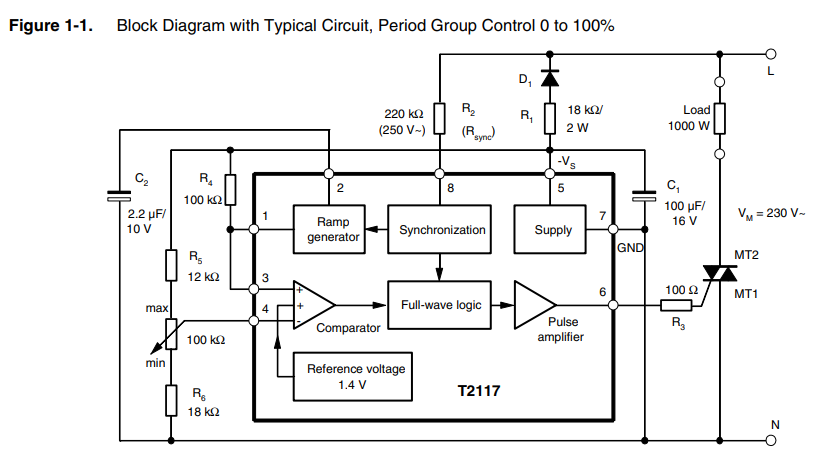
Blockschaltbild und Schaltplan eines Phasenregelkreises
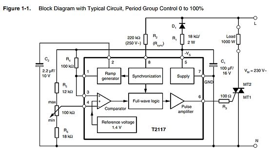
Typical Circuit, Period Group Control 0 to 10% D1 R2 20 kOhm (250 V~) R1 18 kOhm/2 W Load 10 W VS C1 10 uF/16 V VM = 230 V~ MT2 MT1 10 Ohm R3 GND 7 6 5 8 2 1 Ramp generator Synchronization Supply T217 Full-wave logic Pulse amplifier Comparator Reference voltage 1.4 V C2 2.2 uF/10 V R4 10 kOhm R5 12
-
 Bild
Bild
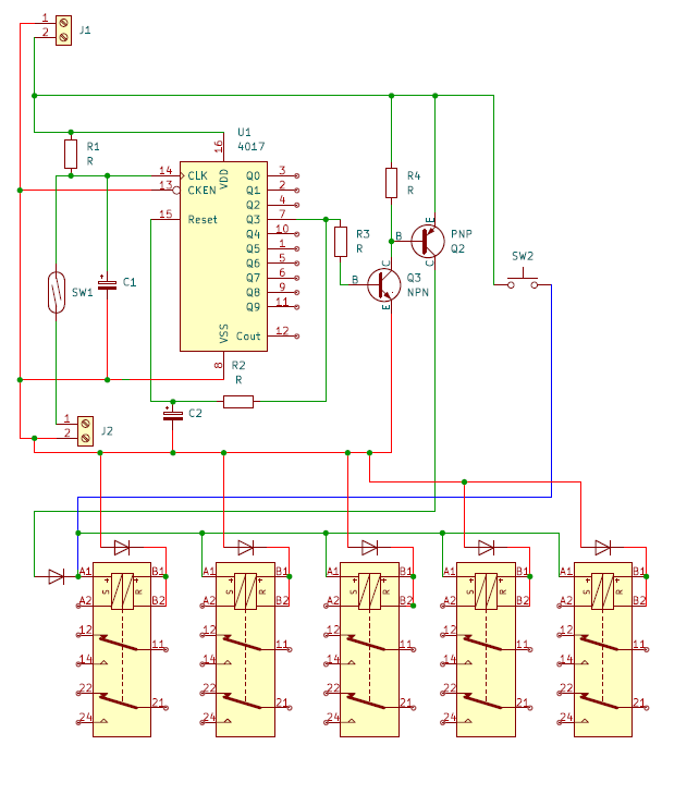
Schaltplan mit IC 4017 und LEDs
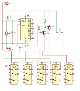
Q2, 7, Q3, PNP, Q4, 1, Q5, 5, Q6, 6, Q7, 7, Q8, 9, Q9, 1, 10, 12, Out, VSS, Reset, 15, VDD, R, R2, C1, SW1, B, B, R3, Q2, Q3, NPN, 1, 2, J2, C2, SW2, A1, B1, A2, B2, 12, 1, 14, 1, 2, 21, 24, 21
-
 Bild
Bild
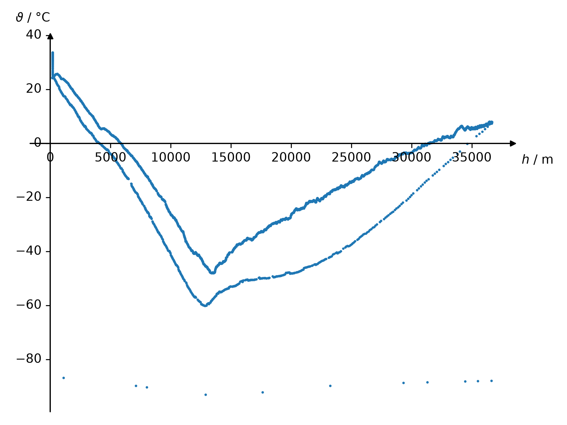
Diagramm von Temperatur über Höhe
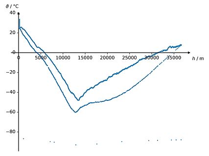
θ / °C 40 20 0 -20 -40 -60 -80 h / m 50 10 150 200 2500 300 350
-
Thread
Neue ESP32-Software, TinyGo, schnelle CCD-Sensoren und anderes mehr
derartigen an – problematisch ist, dass die Inbetriebnahme von SPI- und I2C-Displays erst spät im Bootprozess erfolgte. Im Hause Upton gelobt man an dieser Stelle nun Besserung. 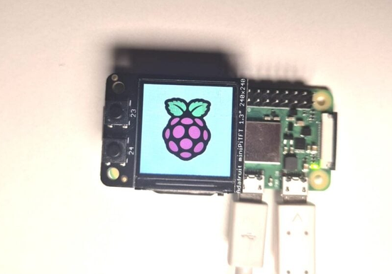 Bildquelle: https://www.raspberrypi.com/news/configure-early-boot-splash-screens-for-spi-and-i2c-based-displays
Minimalprogrammiersprache”, die – auf Kernelebene implementiert – schon beim Hochfahren SPI- und I2C-Befehle abfeuern kann: [c] With the cyberdeck trend inspiring countless colourful Raspberry Pi creations, and the release of new handheld maker devices such as the Cardputer Zero and Hackberry Pi,
-
 Bild
Bild
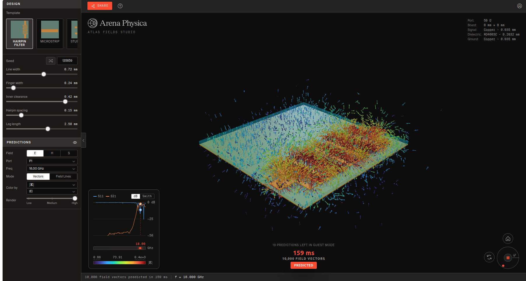
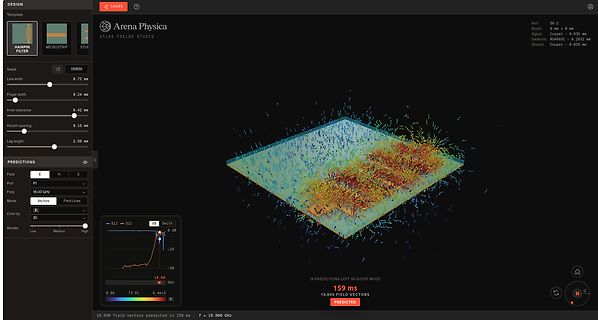
Simulation elektromagnetischer Felder in Arena Physica
Color by E Render Low Medium High Port 50 Ω Board 8 mm x 8 mm Signal Copper - 0.030 mm Dielectric RO403C - 0.2032 mm Ground Copper - 0.035 mm Smith 0 dB -25 -20 18.0 GHz 0.86 73.91 6.4e+3 19 PREDICTIONS LEFT IN GUEST MODE 159 ms 10,0 FIELD VECTORS PREDICTED in 159 ms f = 18.0 GHz
-
 Bild
Bild
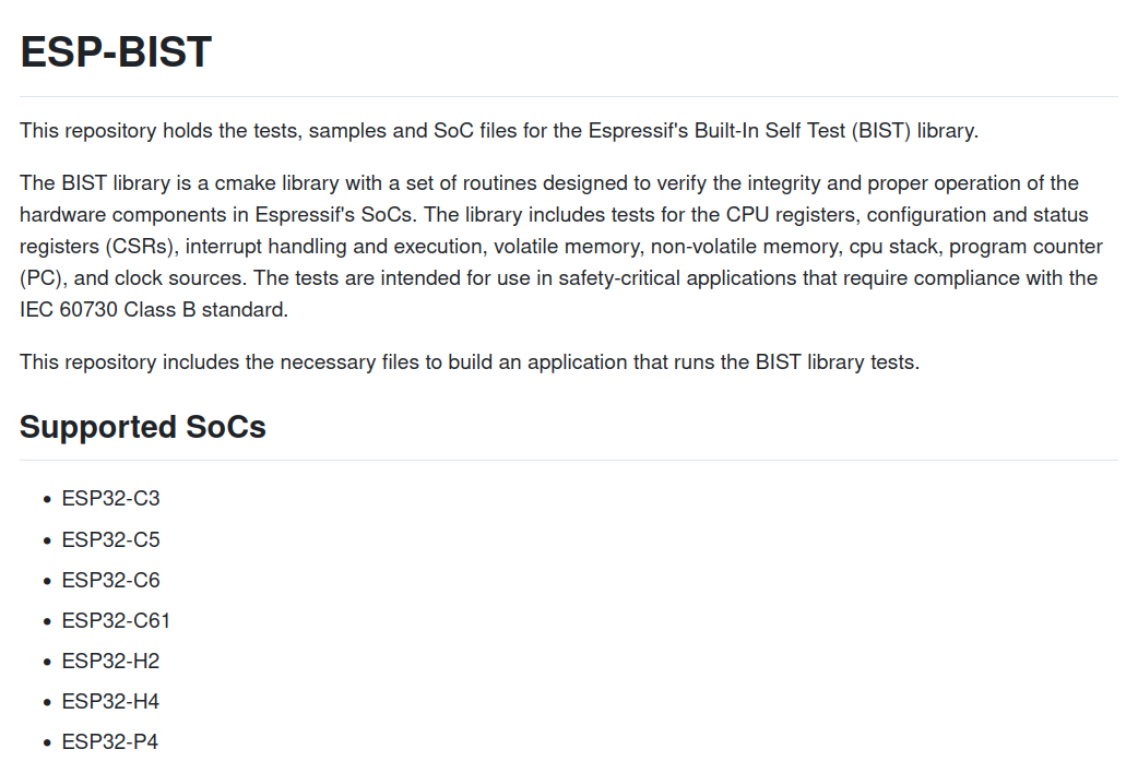
Textbeschreibung der ESP-BIST Bibliothek und unterstützter SoCs
ESP-BIST This repository holds the tests, samples and SoC files for the Espressif's Built-In Self Test (BIST) library. The BIST library is a cmake library with a set of routines designed to verify the integrity and proper operation of the hardware components