-
Datei
atxmega_partlist.txt
Partlist exported from /home/michael/eagle/atxmega128_board/atxmega128_board.sch at 6/1/09 6:21 PM Part Value Device Package Description 10U CPOL-EU153CLV-0405 153CLV-0405 POLARIZED CAPACITOR, European symbol B1 RECTIFIER-DIL RECTIFIER-DIL B-DIL Rectifier
in „Besteht Interesse an einfacher Experimentierplatine fuer den Xmega128a1?“ · Mikrocontroller und Digitale Elektronik ·
-
Datei
help.txt
interface: aWire, debugWIRE, HVPP, HVSP, ISP, JTAG, PDI, TPI or SWD. -d --device <arg> Device name. E.g. atxmega128a1 or at32uc3a0256. -v --verbose Verbose output (debug). -h --host <arg> Target host which runs the backend process. -p --port <arg> Specify which port to use for the backend process. Ignored if
in „atprogram.exe ISP geschwindigkeit einstellen / -cg Option Parameter“ · Mikrocontroller und Digitale Elektronik ·
-
Datei
fehler.txt
dependencies for file: C:\Users\Judith\Documents\Arduino\libraries\U8glib\src\clib\u8g_dev_ssd1351_128x128.c Using cached library dependencies for file: C:\Users\Judith\Documents\Arduino\libraries\U8glib\src\clib\u8g_dev_ssd1353_160x128.c Using cached library dependencies for file: C:\Users\Judith\Documents
in „Marlin auf anet e12“ · Mikrocontroller und Digitale Elektronik ·
-
Datei
Konsolenausgabe.txt
/atxmega64d4 avr/lib/avrxmega5/ avr/lib/avrxmega5/atxmega64a1 avr/lib/avrxmega5/atxmega64a1u avr/lib/avrxmega6/ avr/lib/avrxmega6/atxmega128a3 avr/lib/avrxmega6/atxmega128a3u avr/lib/avrxmega6/atxmega128b1 avr/lib/avrxmega6/atxmega128b3 avr/lib/avrxmega6/atxmega128c3 avr/lib/avrxmega6/atxmega128d3 avr/lib/avrxmega6/atxmega128d4 avr/lib/avrxmega6/atxmega192a3 avr/lib/avrxmega6/atxmega192a3u avr/lib/avrxmega6/atxmega192c3 avr/
in „cannot read spec file 'device-specs/specs-atmega4808'“ · Mikrocontroller und Digitale Elektronik ·
-
Datei
example.html
onclick="submitFirmware(this);"></p> <br/><br/> <p>AVR: <select id="mcu" name="-mcu"> <option value="atxmega128a3u">ATxmega128A3U</option> </select> </p> <p>Clock: <select id="DF_CPU" name="-DF_CPU" value="32000000"> <option selected="selected" value="32000000">32MHz</option> <option value="2000000">2MHz
in „XMega128A3 Kalibrationswerte ADC sind alle 0“ · Mikrocontroller und Digitale Elektronik ·
-
Datei
TimerPrescalersSorted.txt
AT86RF401.xml:16: <CORE_VERSION>V2</CORE_VERSION> AT90CAN128.xml:11754: <TIMER0> AT90CAN128.xml:11762: <Prescaler>1:8:64:256:1024</Prescaler> AT90CAN128.xml:11764: <TIMER1> AT90CAN128.xml:11782: <TIMER2> AT90CAN128.xml:11788: <Prescaler>1:8:32:64:128:256:1024
in „Timer Vorteiler Werte Definition“ · Mikrocontroller und Digitale Elektronik ·
-
Datei
output.txt
c -std=gnu99 -MD -MP -MF "PID_Reglerkarte.d" -MT"PID_Reglerkarte.d" -MT"PID_Reglerkarte.o" -mmcu=atxmega128a1 -o"PID_Reglerkarte.o" ".././PID_Reglerkarte.c" Finished building: .././PID_Reglerkarte.c Building target: PID_Reglerkarte.elf Invoking: AVR/GNU Linker : (AVR_8_bit_GNU_Toolchain_3.4.1_830) 4.6.2
in „strtoul führt zu Kompilerfehler“ · Mikrocontroller und Digitale Elektronik ·
-
Datei
__bootloader__do_spm__apipage.h
/* Dataformat of last page (only 256bytes on atxmega128a4u): * * Offset * 0x000 : 16 Jumpplaces for API (each 4 bytes) (see "__bootloader__apipage" for detail) * * ... no further specific format, yet ... * */ #ifndef SPMINTEREFACE_MAGICVALUE # ifdef
in „[XMega][C] Flash Write möglich aus Anwendung?“ · Mikrocontroller und Digitale Elektronik ·
-
PDF
ATxMega_128_Stick.pdf
ATxMega 128 Stick Inhaltsverzeichnis Platine...................................................................................................................................................... 1 Funktionsübersicht
in „ATxMega Stick“ · Markt ·
-
Datei
adc_dma_test.c
Ausgabe UARTE0 32 MHZ intern, 115200kbs // ** Achtung bitte eigenen Takt einstellen! ** // hier: Atxmega32a4/Atxmega128a1 32Mhz intern */ #include "tools.h" // bindet printf()UARTF0 ein static FILE mystdout_uart = FDEV_SETUP_STREAM(uart_putchar, NULL, _FDEV_SETUP_WRITE); uint8_t daten[16] = {0x30,0x31,0x32,0x33,0x34,0x35,0x36,0x37
in „DMA ATXmega128a1“ · Mikrocontroller und Digitale Elektronik ·
-
PDF
XPLAIN_Shematic.pdf
1 0 9 8 7 6 5 4 3 2 1 0 9 8 7 6 U100 GND AVCC 1 9 9 9 9 9 9 9 9 9 9 8 8 8 8 8 8 8 8 8 8 7 7 7 7 ATxmega128A1-AU ) ) ) ) ) ) 2 D ) ) T T 3 2 ) ) D C ) ) ) ) ) ) ) Analogpower A A A A A A C G L L S E P P C C G V B B B B B B B SDRAM_D3 L100 C C C C F F V A A E T S S E E E E E E E SDRAM_D2 AVCC - - D D
in „Xplain: Schaltplan gesucht“ · Mikrocontroller und Digitale Elektronik ·
-
PDF
man_gcc.pdf
", "atxmega128a3u", "atxmega128b1", "atxmega128b3", "atxmega128c3", "atxmega128d3", "atxmega128d4", "atxmega192a3", "atxmega192a3u", "atxmega192c3", "atxmega192d3", "atxmega256a3", "atxmega256a3b", "atxmega256a3bu", "atxmega256a3u", "atxmega256c3", "atxmega256d3", "atxmega384c3", "atxmega384d3". "avrxmega7" "XMEGA" devices with more than 128@tie{}KiB of program memory and more than 64@tie{}KiB of RAM. mcu@tie{}= "atxmega128a1
in „avr-g++: external linkage von const/PROGMEM Symbol.“ · Mikrocontroller und Digitale Elektronik ·
-
 Bild
Bild
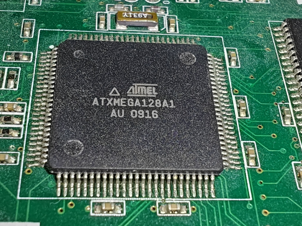
Atmel ATmega128A1 Mikrocontroller auf Leiterplatte
ATMEL ATXMEGA128A1 AU 0916
in „[V] 2 x XMEGA Evaluation Kit XPLAIN“ · Markt · · Platinenfotos
-
PDF
diamex-avr-isp2.pdf
passenden Pin-Num- mern zu ermitteln. HINWEISE, TIPPS! Einige AVR-Controller (z.B. AT90CAN32/64/128, ATMega64/128) haben spezielle Programmierpins PDI, PDO. Bitte benutzen Sie diese Leitungen anstatt MISO/MOSI (siehe Datenblatt). ERFOS-AVR-ISP unterstützt die adaptive SPI-Bitratenanpassung. Eine
in „DIAMEX USB ISP-Programmer für Atmel AVR“ · Mikrocontroller und Digitale Elektronik ·
-
PDF
diamex-avr-isp2.pdf
passenden Pin-Num- mern zu ermitteln. HINWEISE, TIPPS! Einige AVR-Controller (z.B. AT90CAN32/64/128, ATMega64/128) haben spezielle Programmierpins PDI, PDO. Bitte benutzen Sie diese Leitungen anstatt MISO/MOSI (siehe Datenblatt). ERFOS-AVR-ISP unterstützt die adaptive SPI-Bitratenanpassung. Eine
in „AVR Studio 4.19“ · Mikrocontroller und Digitale Elektronik ·
-
Datei
conf_board.h
/** * \file * * \brief ATxmega128A1 on STK600 board configuration template * */ #ifndef CONF_BOARD_H #define CONF_BOARD_H #define CONF_BOARD_ENABLE_USARTC0 #endif // CONF_BOARD_H
in „AVR Xmega USART Interrupt Problem“ · Mikrocontroller und Digitale Elektronik ·
-
Datei
Test_Drehgeber.asm
************************************************************* ;* * ;* * ;* Controller-Typ: AT_XMEGA128A1 * ;* Taktfrequenz: 2 MHz Interner Oszilator * ;* Board: AT XMega128A1 Experimentierboard von Michael G. * ;* * ;* Autor: Steffen Hörhold * ;* Date: 18.10.2009 * ;* Version: 1.0 * ;* Beschreibung:
-
 Bild
Bild
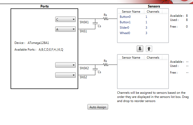
Software-Interface zur Sensor-Konfiguration und Port-Zuweisung
Ports C A Device : ATxmega128A1 Available Ports : A,B,C,D,E,F,H,J,K,Q SNSK1 Rs Cs SNS1 Sensors Sensor Name Channels Button0 1 Button1 1 Slider0 3 Wheel0 3 Available : 8 Used : 8 Free : 0 SNSK2 Rs Cs SNS2 Available : -- Used
in „Atmel QTouch Xplained auf Mega128A1“ · Mikrocontroller und Digitale Elektronik · · Screenshots
-
Datei
main.c
include "main.h" //#include "board.h" // bootloader section start at // 0x20000 --> see datasheet or atxmega128a4 header file //#define BOOT_SECTION_START (0x20000) //#define BOOT_SECTION_SIZE (8192) //#define BOOT_SECTION_PAGE_SIZE (256) //#define BOOT_SECTION_END (BOOT_SECTION_START + BOOT_SECTION_SIZE
in „AVR - Bootloader“ · Mikrocontroller und Digitale Elektronik ·
-
Datei
LCD_Display_atXmega_128_a3.c
// Test LCD Display // Atxmega 128 a3 #include <avr/io.h> #include "lcd-routines.h" #include <avr/interrupt.h> #include <avr/pgmspace.h> #include <util/delay.h> #include <stdio.h> #include <stdlib.h> int main(void) { // Initialisierung
in „At xmeg 128 (3,3V) mit LCD Display (5V) verbinden (in C)“ · Mikrocontroller und Digitale Elektronik ·
-
Datei
Test_Xmega.asm
.include "ATxmega128A1def.inc" ;***** Register-Variablen ;.def Name = r0 ; Erläuterung ;.def Name = r1 ; Erläuterung ;.def Name = r2 ; Erläuterung ;.def Name = r3 ; Erläuterung ;.def Name = r4 ; Erläuterung ;.def Name
in „ATXMega128 - Erste Erfahrungen“ · Mikrocontroller und Digitale Elektronik ·
-
Datei
Test_Xmega.asm
.include "ATxmega128A1def.inc" ;***** Register-Variablen ;.def Name = r0 ; Erläuterung ;.def Name = r1 ; Erläuterung ;.def Name = r2 ; Erläuterung ;.def Name = r3 ; Erläuterung ;.def Name = r4 ; Erläuterung ;.def Name
-
PDF
xminilab-manual.pdf
1.6 - February, 2012 Page | 7 Xminilab User’s Manual 1.3 Specifications General Specifications: - ATXMEGA32A4U 36KB Flash, 4KB SRAM, 1KB EEPROM. - Graphic OLED display 2.42", 128x64 pixels. 40,000 hours minimum life time (to 50% original brightness). - Module size: 3.3" x 1.75". - PDI interface. - 4 tactile
in „USART - xmodem (Xminilab) - Bildübertragung“ · Mikrocontroller und Digitale Elektronik ·
-
PDF
xminilab-manual.pdf
1.6 - February, 2012 Page | 7 Xminilab User’s Manual 1.3 Specifications General Specifications: - ATXMEGA32A4U 36KB Flash, 4KB SRAM, 1KB EEPROM. - Graphic OLED display 2.42", 128x64 pixels. 40,000 hours minimum life time (to 50% original brightness). - Module size: 3.3" x 1.75". - PDI interface. - 4 tactile
in „ATXmega32 flashen mit ATMEL Flip (Xminilab)“ · Mikrocontroller und Digitale Elektronik ·
-
Datei
usart_test.c
/* // // // Atxmega128a3, intern 32Mhz // USARTD0, 9600bps (siehe usart.c) AVR-STUDIO 6.1 // */ #include "tools.h" int main(void) { system_clocks_init(); // Init Clock Rs232_Init(); // USARTD0 Init _delay_ms(100); //
in „XMega USART Probleme“ · Mikrocontroller und Digitale Elektronik ·
-
Datei
main.c
ioport.h" #include <util/delay.h> int main(void) { uint8_t tx_buf[] = "This is the STK 600 with an ATxmega 128A1:\n"; uint32_t i=0,j=0; /* Initialize the board. * The board-specific conf_board.h file contains the configuration of * the board initialization. */ board_init(); /* Initialize the system clock
in „AVR Xmega USART Interrupt Problem“ · Mikrocontroller und Digitale Elektronik ·
-
Datei
DmxReceiverXmega.c
// // *** DMX-Receiver mit ATXmega128-A1 *** // #include <avr/io.h> #include <avr/interrupt.h> volatile uint8_t DmxRx_status = 0; volatile uint16_t DmxRx_ChannelCounter = 0; volatile uint8_t DmxRx_Value[514]; void dmx_init(void); void
in „DMX-Receiver mit xmega - UART empfängt nur Müll“ · Mikrocontroller und Digitale Elektronik ·
-
PDF
XMEGA-A3BU_XPLAINED_Design_Documentation_rev2.PDF
FILTER_OUT UT P U T E / U U S L GND E O T T GND A I R T Q Q F D U200 04631 6 6 9 8 7 645 5 315 5 5 9 ATxmega256A3BU-AU A A AC N R R E T F F C N A F F 32 kHz Crystal J3 PIN0 ADCA0_LIGHT_SENSOR ) ) )A G ) ) E D P P V G V ) ) PIN1 ADCA1_NTC_SENSOR A A A L L / I 0 D PIN2 ADCA2_FILTER D D D T T L P O T These
in „LED toggeln mit ATxmega256A3BU“ · Mikrocontroller und Digitale Elektronik ·
-
Datei
main.c
average=0; j=0; do { average+= (uint8_t)((*q1++)-0x80); } while(++j); j = (uint8_t )(average>>8); if(j>=128) offset=-(j-128); else offset = (128-j); eeprom_write_byte((uint8_t *)&offsetsCH1[i], offset); printN(offset+128); // Calculate offset for CH2 average=0; j=0; do { average+= (uint8_t)((*q2++)-0x80); } while(++j); j = (uint8_t )(average>>8); if(j>=128) offset=-(j-128); else offset = (128-j); eeprom_write_byte((uint8_t *)&offsetsCH2[i], offset); printN(offset+128); show_display(); } //_delay_ms(2000); } // Fill up channel data buffers void SimpleADC
in „ATXmega - Pin Eingang oder Ausgang“ · Mikrocontroller und Digitale Elektronik ·
-
PDF
TeileATxMega4.pdf
1 100u ELKO‐D C66 1 3n3 C0603 C68 1 100p C0603 C71 2 15p C0603 C81, C82 1 MCP2200 SO‐20W IC101 1 ATXMEGA128 TQPF100 IC21 1 XRP7664 SO‐08Pad IC61 1 ENC28J60 SO28W IC81 1 MAX232 SO‐16 IC82 1 1u L0805 L101 1 10u L‐PIS28 L61 1 4u7 L‐EUL0805 L62 1 1u L0805 L81 3 Gelb LED0603 LED101, LED102, LEDSD 4 Rot LED1206
in „ATxMegaBoard 4“ · Markt ·
-
Datei
adc_dma_test.c
void); // UARTE0 16 MHZ intern, 115200kbs // ** Achtung bitte eigenen Takt einstellen! ** // hier: Atxmega128a3 16Mhz */ #include "tools.h" #define ADCACAL0_offset 0x20 // zum Auslesen ADC Offset aus Flash #define ADCACAL1_offset 0x21 // dsgl // bindet printf()UARTF0 ein static FILE mystdout_uart = FDEV_SETUP_STREAM
in „ATXMega128a1 Problem mit printf()-Funktion“ · Mikrocontroller und Digitale Elektronik ·
-
Datei
pwm_test.c
//--------------------------------------------------------------- // ATXMEGA128A3 32 MHz // -------------------------------------------------------------- #include "tools.h" int main(void) { system_clocks_init(); // Clock ein PORTC.DIR |= (1<<PIN0)|(1<<PIN1)|(1<<PIN2)|(1<<
in „XMEGA PWM, Timer-Probleme und USART Probleme“ · Mikrocontroller und Digitale Elektronik ·
-
Datei
main.c
AT90USB1287"); #else #error "unknown PAL_TYPE"; #endif #elif (PAL_GENERIC_TYPE == XMEGA) #if (PAL_TYPE == ATXMEGA128A1) printf("ATxmega128A1"); #else #error "unknown PAL_TYPE"; #endif #elif (PAL_GENERIC_TYPE == MEGA_RF) #if (PAL_TYPE == ATMEGA128RFA1) printf("ATmega128RFA1"); #else #error "unknown PAL_TYPE";
in „performance Testprogramm Atmel MAC“ · HF, Funk und Felder ·
-
Datei
usart_test.c
/* // Atxmega128a3, intern 32Mhz // USARTD0, 9600bps (siehe usart.c) AVR-STUDIO 6.1 // */ #include <util/delay.h> #include <avr/interrupt.h> #include <avr/pgmspace.h> #include <avr/io.h> #include <stdbool.h> #include
in „XMega USART Probleme“ · Mikrocontroller und Digitale Elektronik ·
-
Datei
adc_dma_usart.c
GND // Referenz 2.048 Volt an ADC_REFSEL_AREFB (PINB6) // DMA.CH0/DMA.CH1 siehe dma_init(void); // Atxmega128a3u 32 MHZ intern // UARTF0 115200kbs, */ #include "tools.h" // bindet printf()UARTF0 ein static FILE mystdout_uart = FDEV_SETUP_STREAM(uart_putchar, NULL, _FDEV_SETUP_WRITE); uint16_t samples_0
in „Problem mit XEMGA ADC“ · Mikrocontroller und Digitale Elektronik ·
-
PDF
avr-libc-user-manual-1.8.0.pdf
at90usb1287 • atmega8u2 • atmega16u2 • atmega16u4 • atmega32u2 • atmega32u4 • atmega32u6 XMEGA Devices: • atxmega16a4 • atxmega16d4 • atxmega32a4 • atxmega32d4 • atxmega64a1 • atxmega64a1u • atxmega64a3 • atxmega64d3 • atxmega128a1 • atxmega128a1u • atxmega128a3 • atxmega128d3 • atxmega192a3 • atxmega192d3 • atxmega256a3 • atxmega256a3b • atxmega256d3 Generated on Tue Jan 3 2012 17:00:59 for avr-libc by Doxygen 1.3 Supported Devices 9 Miscellaneous Devices: • at94K [2] • at76c711 [3] • at43usb320 • at43usb355
in „Interrupt Probleme beim Arduino“ · Mikrocontroller und Digitale Elektronik ·
-
Datei
src_code.txt
.include "ATxmega128A1def.inc" .def tempreg=r16 .def counterreg=r17 .def outputreg=r22 .equ DIR_PORTA_MASK=0xA8 .equ DIR_PORTB_MASK=0x02 .equ KEY_INTERRUPT_MASK=0x04 .org 0x0 rjmp RESET .org PORTB_INT0_vect rjmp ISR
in „ATxmega128A1 Port Interrupt“ · Mikrocontroller und Digitale Elektronik ·
-
Datei
testLED.c
-------------------------------------------- // // Project: Taster LED // Date: // Hardware: hD2 ATXMEGA128A1 // Note: heirob //Created: 03.04.2015 //----------------------------------------------------------------------------- #define F_CPU 16000000UL // Taktfrequenz 16 MHz #include <avr/io.h> // AVR
in „C-Neuling versucht sich“ · Mikrocontroller und Digitale Elektronik ·
-
Datei
RFM70_HH.c
Port F Pin 4 #define LED_1_bm 32 // Port F Pin 5 #define LED_2_bm 64 // Port F Pin 6 #define LED_3_bm 128 // Port F Pin 7 #define SWITCHPORT PORTF #define SWITCH_REC_bm 2 // Port F Pin 1 #define SWITCHMASK 2 // Port F Pin 1 #define TIMEOUT 0xFF00 // for UART (TCC1) = ca 4 s #define device_no 1 // Device
in „RFM70 arbeitet nicht zuverlässig“ · HF, Funk und Felder ·
-
PDF
tbl.pdf
mithilfe des Mono-Frameworks andere .NET Sprachen Windows nicht getestet, sollte abe¨ moglich sein AtXMega128A1 Atmel uC nur Broadcasts und Daten- bzw. Befehlstransfer (mit Antwort) AtMega162 Atmel uC nur Daten- und Kommandobroadcasts, USART0 2.1.3 Kurzbeschreibung und Aufbau In aufw¨ndigeren industriellen
in „API-Feedback / Protokollfeedback: Kommunikationsstack für serielle Bussysteme“ · Mikrocontroller und Digitale Elektronik ·
-
Datei
spi_driver.h
##### For : Xmega SPI Version : 1.0 Date : modified 06.09.2012 autor : Martin Junghans Hardware: ATXmega128A3-U, 32MHz at 16Mhz extern Task : siehe oben //################################################################################################*/ #ifndef SPI_DRIVER_H #define SPI_DRIVER_H #include
in „ATXMega32e5 SPI MISO immer 0 mit AT45DB161 Flash IC“ · Mikrocontroller und Digitale Elektronik ·
-
Datei
output.txt
sending 1 bytes avrdude: jtagmkII_recv(): Got message seqno 2 (command_sequence == 2) OK AVR Part : ATXMEGA128A1 Chip Erase delay : 0 us PAGEL : P00 BS2 : P00 RESET disposition : dedicated RETRY pulse : SCK serial program mode : yes parallel program mode : yes Timeout : 0 StabDelay : 0 CmdexeDelay : 0 SyncLoops
in „xmega mit JTAG ICE MKII unter Linux: RSP_ILLEGAL_EMULATOR_MODE“ · Mikrocontroller und Digitale Elektronik ·
-
Datei
gcc9.2_binutils2.34_Konsolenausgabe.txt
/atxmega64d4 avr/lib/avrxmega5/ avr/lib/avrxmega5/atxmega64a1 avr/lib/avrxmega5/atxmega64a1u avr/lib/avrxmega6/ avr/lib/avrxmega6/atxmega128a3 avr/lib/avrxmega6/atxmega128a3u avr/lib/avrxmega6/atxmega128b1 avr/lib/avrxmega6/atxmega128b3 avr/lib/avrxmega6/atxmega128c3 avr/lib/avrxmega6/atxmega128d3 avr/lib/avrxmega6/atxmega128d4 avr/lib/avrxmega6/atxmega192a3 avr/lib/avrxmega6/atxmega192a3u avr/lib/avrxmega6/atxmega192c3 avr/
in „Toochain bauen avr-gcc-x.x mit binutils-2.34 funktioniert nicht“ · Mikrocontroller und Digitale Elektronik ·
-
Datei
gcc10.0.1_binutils2.34_Konsolenausgabe_b.txt
/atxmega64d4 avr/lib/avrxmega5/ avr/lib/avrxmega5/atxmega64a1 avr/lib/avrxmega5/atxmega64a1u avr/lib/avrxmega6/ avr/lib/avrxmega6/atxmega128a3 avr/lib/avrxmega6/atxmega128a3u avr/lib/avrxmega6/atxmega128b1 avr/lib/avrxmega6/atxmega128b3 avr/lib/avrxmega6/atxmega128c3 avr/lib/avrxmega6/atxmega128d3 avr/lib/avrxmega6/atxmega128d4 avr/lib/avrxmega6/atxmega192a3 avr/lib/avrxmega6/atxmega192a3u avr/lib/avrxmega6/atxmega192c3 avr/
in „Toochain bauen avr-gcc-x.x mit binutils-2.34 funktioniert nicht“ · Mikrocontroller und Digitale Elektronik ·
-
Datei
gcc10_binutils2.33.1_flex_Konsolenausgabe.txt
/atxmega64d4 avr/lib/avrxmega5/ avr/lib/avrxmega5/atxmega64a1 avr/lib/avrxmega5/atxmega64a1u avr/lib/avrxmega6/ avr/lib/avrxmega6/atxmega128a3 avr/lib/avrxmega6/atxmega128a3u avr/lib/avrxmega6/atxmega128b1 avr/lib/avrxmega6/atxmega128b3 avr/lib/avrxmega6/atxmega128c3 avr/lib/avrxmega6/atxmega128d3 avr/lib/avrxmega6/atxmega128d4 avr/lib/avrxmega6/atxmega192a3 avr/lib/avrxmega6/atxmega192a3u avr/lib/avrxmega6/atxmega192c3 avr/
in „Toochain bauen avr-gcc-x.x mit binutils-2.34 funktioniert nicht“ · Mikrocontroller und Digitale Elektronik ·
-
Datei
spi_driver.c
##### For : Xmega SPI Version : 1.0 Date : modified 06.09.2012 autor : Martin Junghans Hardware: ATXmega128A3-U, 32MHz at 16Mhz extern Task : siehe oben //################################################################################################*/ #include "spi_driver.h" /*! \brief Initialize SPI
in „Micro SD Karte SPI an Xmega“ · Mikrocontroller und Digitale Elektronik ·
-
Datei
spi_driver.c
##### For : Xmega SPI Version : 1.0 Date : modified 06.09.2012 autor : Martin Junghans Hardware: ATXmega128A3-U, 32MHz at 16Mhz extern Task : siehe oben //################################################################################################*/ #include "spi_driver.h" /*! \brief Initialize SPI
in „ATXMega32e5 SPI MISO immer 0 mit AT45DB161 Flash IC“ · Mikrocontroller und Digitale Elektronik ·
-
PDF
atmel-42330-atmel-ice_userguide.pdf
the chain is limited to 15 before and 15 after. Tip: Daisy chaining example: TDI → ATmega1280 → ATxmega128A1 → ATUC3A0512 → TDO. ® In order to connect to the Atmel AVR XMEGA device, the daisy chain settings are: • Devices before: 1 • Devices after: 1 • Instruction bits before: 4 (8-bit AVR devices have
in „AVRISP mkII Connect Failed“ · Mikrocontroller und Digitale Elektronik ·
-
PDF
Atmel-ICE_UserGuide.pdf
the chain is limited to 15 before and 15 after. Tip: Daisy chaining example: TDI → ATmega1280 → ATxmega128A1 → ATUC3A0512 → TDO. ® In order to connect to the Atmel AVR XMEGA device, the daisy chain settings are: • Devices before: 1 • Devices after: 1 • Instruction bits before: 4 (8-bit AVR devices have
in „Atmel ICE Programmer und UPDI“ · Mikrocontroller und Digitale Elektronik ·
-
Datei
AVR.html
style="width: 8.485%;" class="hcp28" bgcolor="#c8d0e0" width="8.485%"> <p class="hcp2" align="right">ATxmega128A1</p> </td> <td colspan="1" rowspan="1" style="width: 6.776%;" class="hcp29" bgcolor="#c8d0e0" width="6.776%"> <p class="hcp14" align="center"><span class="hcp15">a</span></p> </td> <td colspan
in „Billige Alternative zu AVR STK 500 oder Wie brenne ich günstig mein Programm auf den Mikrochip?“ · Mikrocontroller und Digitale Elektronik ·