-
PDF
Testboard_KK32F7.PDF
P uSD_D1D 0 D 1 PICON2DAT1 CD PICON200010 P SDCLK C L K PIU2000CLK 01 P 01 01 P01 01 01 01 microSD-693071010811 P NBL0B L 0 PIU2000LDQM / / / / / / / P NBL1B L 1 PIU2000UDQM n n n n n n n P SD_CD 0 C D 1 1 1 1 1 1 1 0COR2 +3V3 PIU2000VDDQ VSSQ PIU20006
in „STM32F7 Discovery Board“ · Mikrocontroller und Digitale Elektronik ·
-
Datei
NRF24_SendRcvMIesp.ino
DEFAULT_SEND_CHANNEL (75) // 40 = Default channel for Hoymiles, 61 #define DEFAULT_RF_DATARATE (RF24_250KBPS) // Datarate #include "NRF24_sniff_types.h" static HM_Packets hmPackets; static uint32_t tickMillis; static uint32_t UpdateTick; // Set up nRF24L01 radio on SPI bus plus CE/CS pins // If more than one RF24 unit is used the another CS pin than 10 must be used // This pin is used hard coded in SPI library static RF24 radio1 (RF1_CE_PIN, RF1_CS_PIN); static NRF24_packet_t bufferData[PACKET_BUFFER_SIZE]; static
in „Wechselrichter Hoymiles HM-xxxx 2,4 GhZ Nordic Protokoll?“ · Mikrocontroller und Digitale Elektronik ·
-
Datei
NRF24_SendRcvMIesp.ino
DEFAULT_SEND_CHANNEL (75) // 40 = Default channel for Hoymiles, 61 #define DEFAULT_RF_DATARATE (RF24_250KBPS) // Datarate #include "NRF24_sniff_types.h" static HM_Packets hmPackets; static uint32_t tickMillis; static uint32_t UpdateTick; // Set up nRF24L01 radio on SPI bus plus CE/CS pins // If more than one RF24 unit is used the another CS pin than 10 must be used // This pin is used hard coded in SPI library static RF24 radio1 (RF1_CE_PIN, RF1_CS_PIN); static NRF24_packet_t bufferData[PACKET_BUFFER_SIZE]; static
in „Wechselrichter Hoymiles HM-xxxx 2,4 GhZ Nordic Protokoll?“ · Mikrocontroller und Digitale Elektronik ·
-
Datei
NRF24_SendRcvMIesp.ino
DEFAULT_SEND_CHANNEL (75) // 40 = Default channel for Hoymiles, 61 #define DEFAULT_RF_DATARATE (RF24_250KBPS) // Datarate #include "NRF24_sniff_types.h" static HM_Packets hmPackets; static uint32_t tickMillis; static uint32_t UpdateTick; // Set up nRF24L01 radio on SPI bus plus CE/CS pins // If more than one RF24 unit is used the another CS pin than 10 must be used // This pin is used hard coded in SPI library static RF24 radio1 (RF1_CE_PIN, RF1_CS_PIN); static NRF24_packet_t bufferData[PACKET_BUFFER_SIZE]; static
in „Wechselrichter Hoymiles HM-xxxx 2,4 GhZ Nordic Protokoll?“ · Mikrocontroller und Digitale Elektronik ·
-
Datei
hauptfunktion.c
FOSC 8000000UL #include <avr/io.h> #include <avr/interrupt.h> #include <util/delay.h> #include "nRF24L01.h" #include "nrf24.h" #include "spi.h" #include "setbit.h" /* -- USART -- */ #define USART_BAUD 1200 #define USART_MYUBRR FOSC/16/USART_BAUD-1 /* -- -- */ ISR (TIMER0_OVF_vect); ISR (INT0_vect); void
in „NRF24L01 und Atmega328P“ · Mikrocontroller und Digitale Elektronik ·
-
Datei
nRF24L01_.h
OF OR IN CONNECTION WITH THE SOFTWARE OR THE USE OR OTHER DEALINGS IN THE SOFTWARE. */ #ifndef _LIB_NRF24L01_H_ #define _LIB_NRF24L01_H_ #include <avr/io.h> #include <stdbool.h> #include <spi.h> /****************************************************************************** * Project Specific Settings
in „nRF24L01+ Funkmodul - Auto Acknowledgement sendet keine Payload“ · Mikrocontroller und Digitale Elektronik ·
-
Datei
nrf24l01_usr.h
#ifndef NRF24L01_USR_H_INCLUDED #define NRF24L01_USR_H_INCLUDED /* -------------- Standard Include Files ----------------- */ /* ---------------System Include Files / Librarys -------- */ #include "stm32f10x_conf.h
in „[STM32F4xx] NRF24L01+ Funkmodul Source Code“ · Projekte & Code ·
-
Datei
NRF24_SendRcvMIesp.ino
DEFAULT_SEND_CHANNEL (75) // 40 = Default channel for Hoymiles, 61 #define DEFAULT_RF_DATARATE (RF24_250KBPS) // Datarate #include "NRF24_sniff_types.h" static HM_Packets hmPackets; static uint32_t tickMillis; static uint32_t UpdateTick; // Set up nRF24L01 radio on SPI bus plus CE/CS pins // If more than one RF24 unit is used the another CS pin than 10 must be used // This pin is used hard coded in SPI library static RF24 radio1 (RF1_CE_PIN, RF1_CS_PIN); static NRF24_packet_t bufferData[PACKET_BUFFER_SIZE]; static
in „Wechselrichter Hoymiles HM-xxxx 2,4 GhZ Nordic Protokoll?“ · Mikrocontroller und Digitale Elektronik ·
-
PDF
matching_nrf24_to_100ohms_balanced_-_Nordic_DevZone.pdf
matching nrf24 to 100ohms balanced iot_newb 10 months ago I want to use the nrf24l01+ with the se2436 apmlifier, but the input of the amplifier requires an input of 100ohms balanced, while the nrf24 has a balanced
-
Datei
nRF24L01_Tutorial_RX_-_MAIN.c
/* * nRF24L01_Tutorial_RX.c * * Created: 06.01.2012 22:51:57 * Author: Ernst Buchmann */ #ifndef F_CPU //define F_CPU if not done #define F_CPU 20000000UL #endif #include <avr/io.h> #include <avr/interrupt.h> #
in „2,4 Ghz Kommunikation“ · Mikrocontroller und Digitale Elektronik ·
-
Datei
main_RX.c
/* * nRF24L01_Tutorial_RX.c * * Created: 06.01.2012 22:51:57 * Author: Ernst Buchmann */ #ifndef F_CPU //define F_CPU if not done #define F_CPU 16000000UL #endif #include <avr/io.h> #include <avr/interrupt.h> #
in „Probleme mit NRF24L01 Tutorial“ · Mikrocontroller und Digitale Elektronik ·
-
 Bild
Bild
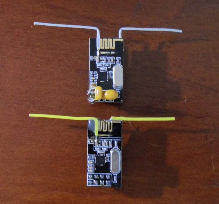
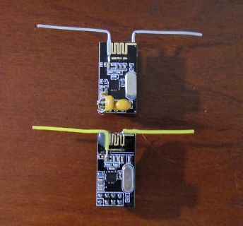
Zwei kleine Leiterplatten mit Antennen
nrf24l01_antenne.jpg
in „Umbau NRF24L01 mit Dipolantenne“ · HF, Funk und Felder · · Platinenfotos
-
Datei
NRF24l01-Sender.ino
#include <Arduino.h> #include <SPI.h> #include <RH_NRF24.h> #include "LowPower.h" // Singleton instance of the radio driver RH_NRF24 nrf24; uint8_t pos = 4; uint8_t counter = 0; uint8_t chk = 0; void setup() { Serial.begin(9600); while (!Serial) ; // wait for serial port to connect. Needed for Leonardo only if (!nrf24.init()) { Serial.println("init failed"); } // Defaults after init are 2.402 GHz (channel 2), 2Mbps, 0dBm if (!nrf24.setChannel(3)) { Serial.println("setChannel failed"); } if (!nrf24.setRF(RH_NRF24::DataRate2Mbps, RH_NRF24::TransmitPower0dBm)) { Serial.println("setRF failed"); } Serial.println
in „Arduino mit NRF04l01 - Problem im PowerDown“ · Mikrocontroller und Digitale Elektronik ·
-
Datei
arduino328.ino
avr/io.h> /* C standard Libs */ #include <stdint.h> /* Projekt Libs */ #include <SPI.h> #include <nRF24L01.h> #include <DHT.h> #include <printf.h> #include <RF24.h> #include <RF24_config.h> #include <DallasTemperature.h> #include <OneWire.h> #define DHTTYPE DHT22 // DHT 22 (AM2302), AM2321 #define DHTPIN 2 // what digital pin we're connected to #define CE_PIN 8 // CE NRF24L01 #define CSN_PIN 7 // CSN NRF24L01 #define RF_CHANNEL 75 // Der Transfer Datensatz struct data_t { uint16_t id; uint16_t nr; float temperatur_1; float temperatur_2; float feuchte; float ubatt; }
in „NRF24L01+ auf STM32F103: Ich weiss nicht mehr weiter :-(“ · Mikrocontroller und Digitale Elektronik ·
-
Datei
usart_nrf.h
#ifndef __USART_NRF_H #define __USART_NRF_H #ifdef DTU3PRO #include "stm32f4xx.h" #define UsartNrf USART3 #else #include "stm32f10x.h" #define UsartNrf USART2 #endif #include <math.h> #include <stdlib.h> #include <stdio.h
in „Wechselrichter Hoymiles HM-xxxx 2,4 GhZ Nordic Protokoll?“ · Mikrocontroller und Digitale Elektronik ·
-
Datei
iO.c
1 << ADPS0 ); while(1) { //Initialisierung von NRF24L01 wl_module_init(); _delay_ms(50); sei(); wl_module_tx_config(wl_module_TX_NR_0); //ADC auslesen l = adc_read(1); //DHT22 auslesen if(dht_gettemperaturehumidity(&temperature, &humidity) != -1) {
in „AVR Programm läuft nur fehlerfrei direkt nach Programmierung mittels ISP“ · Mikrocontroller und Digitale Elektronik ·
-
Datei
niO.c
1 << ADPS0 ); while(1) { //Initialisierung von NRF24L01 wl_module_init(); _delay_ms(50); sei(); wl_module_tx_config(wl_module_TX_NR_0); //ADC auslesen l = adc_read(1); //DHT22 auslesen if(dht_gettemperaturehumidity(&temperature, &humidity) != -1) {
in „AVR Programm läuft nur fehlerfrei direkt nach Programmierung mittels ISP“ · Mikrocontroller und Digitale Elektronik ·
-
Datei
usart_nrf.c
(&(MIReal[PortNO].Data.Freque[0]), &(pBuffer[22]), 2); } if(UsartNrf_Process_ExceptionFilter(pBuffer, 24, 25, 2000) == true) { memcpy(&(MIReal[PortNO].Data.Temper[0]), &(pBuffer[24]), 2); } } else if(pBuffer[10] == 0x11) { memcpy(&(MIReal[PortNO].Data.Run_Status[0]),
in „Wechselrichter Hoymiles HM-xxxx 2,4 GhZ Nordic Protokoll?“ · Mikrocontroller und Digitale Elektronik ·
-
Datei
attiny84_24ghz.ino
avr/io.h> /* C standard Libs */ #include <stdint.h> /* Projekt Libs */ #include <SPI.h> #include <nRF24L01.h> #include <DHT.h> #include <printf.h> #include <RF24.h> #include <RF24_config.h> #include <DallasTemperature.h> #include <OneWire.h> #define DHTTYPE DHT22 // DHT 22 (AM2302), AM2321 #define DHTPIN 2 // what digital pin we're connected to #define CE_PIN 8 // CE NRF24L01 #define CSN_PIN 7 // CSN NRF24L01 #define RF_CHANNEL 80 /* ACK Datensatz */ struct { uint8_t feuchte_enable, // 1 = Sende Feuchtedaten temp1_enable, // 1 = Sende Temp Sensor 1 Daten temp2_enable
in „[STM32F4xx] NRF24L01+ Funkmodul Source Code“ · Projekte & Code ·
-
Datei
arduino328.ino
avr/io.h> /* C standard Libs */ #include <stdint.h> /* Projekt Libs */ #include <SPI.h> #include <nRF24L01.h> #include <DHT.h> #include <printf.h> #include <RF24.h> #include <RF24_config.h> #include <DallasTemperature.h> #include <OneWire.h> #define DHTTYPE DHT22 // DHT 22 (AM2302), AM2321 #define DHTPIN 2 // what digital pin we're connected to #define CE_PIN 8 // CE NRF24L01 #define CSN_PIN 7 // CSN NRF24L01 #define RF_CHANNEL 75 /* ACK Datensatz */ struct { uint8_t feuchte_enable, // 1 = Sende Feuchtedaten temp1_enable, // 1 = Sende Temp Sensor 1 Daten temp2_enable
in „Zeigt her eure Kunstwerke (2017-2019)“ · Projekte & Code ·
-
Datei
wl_module.c
actual address to be used. It should be sized // according to the tx_addr length specified to the nrf24l01. //unsigned int len is the length of the address. Its value should be specified // according to the tx_addr length specified to the nrf24l01. extern void wl_module_set_tx_addr(uint8_t * address
in „2,4 Ghz Kommunikation“ · Mikrocontroller und Digitale Elektronik ·
-
Datei
nRF24L01_Testreceiver.c
/* * nRF24L01_Testempfänger.c * * Created: 06/13/2016 16:53:10 * Author: thobe PB0: CE PB1: CSN PB2: SSnot PB3: MOSI PB4: MISO PB5: SCK PB6: XTAL PB7: XTAL PC0: PC1: PC2: PC3: PC4: PC5: RESETnot: 3,3V PD0: PD1:
in „NRF24L01 und Atmega328P“ · Mikrocontroller und Digitale Elektronik ·
-
Datei
wl_module.c
actual address to be used. It should be sized // according to the tx_addr length specified to the nrf24l01. //unsigned int len is the length of the address. Its value should be specified // according to the tx_addr length specified to the nrf24l01. extern void wl_module_set_tx_addr(uint8_t * address
in „NRF24L01 und Atmega328P“ · Mikrocontroller und Digitale Elektronik ·
-
Datei
wl_module.c
actual address to be used. It should be sized // according to the tx_addr length specified to the nrf24l01. //unsigned int len is the length of the address. Its value should be specified // according to the tx_addr length specified to the nrf24l01. extern void wl_module_set_tx_addr(uint8_t * address
in „NRF24L01 und Atmega328P“ · Mikrocontroller und Digitale Elektronik ·
-
Datei
wl_module.c
actual address to be used. It should be sized // according to the tx_addr length specified to the nrf24l01. //unsigned int len is the length of the address. Its value should be specified // according to the tx_addr length specified to the nrf24l01. extern void wl_module_set_tx_addr(uint8_t * address
in „NRF24L01 und Atmega328P“ · Mikrocontroller und Digitale Elektronik ·
-
Datei
0.4.25_SD_Setup_V2.diff
invRetry\" value=\"{INV_RETRIES}\"/><p class=\"des\">Pinout (Wemos)</p>{PINOUT}<p class=\"des\">Radio (NRF24L01+)</p><label for=\"rf24Power\">Amplifier Power Level</label><select name=\"rf24Power\">{RF24}</select><p class=\"des\">MQTT</p><label for=\"mqttAddr\">Broker / Server IP</label><input type=\"text
in „Wechselrichter Hoymiles HM-xxxx 2,4 GhZ Nordic Protokoll?“ · Mikrocontroller und Digitale Elektronik ·
-
PDF
WHCS-BS-18-002_REV_A.pdf
3V 50 V 10uF +5V IC5 100nF IC1 IN OUT R4 A 3 8 S C11 10k IC7 A FB 4 BP S 7 GND 1uF 3 D4 FB S CE S 1 L1 +5V GND EN BP CS 4 CSN L D 5 D S 2 GND SCK 5 SCK + RFB0807-681L AP2112K-3.3TRG1 MOSI 6 MOSI 0 ERZ-V05D431 RV1 GL41 C9 LNK302GN C10 ME6211 MISO 7 MISO 4 U D7 47uF R26 2 D6 3.9uF 450V US1J 4.2k NRF_IRQ
-
PDF
TOBBY.pdf
Accelerometer analog 3-way (X,Y,Z) Balancer No need of a third wheel (like a Segway) Communication Wireless NRF24L01+ compatible interface or USART bluethooth interface or WLAN Position Detection LPDS (Local Position Detection System) triggered by radio-signal and measured by sonar (precision +/- 5..10mm) for
in „TOBBY THE ROBBY“ · Markt ·
-
PDF
nrf.pdf
Revision: 1.0 Page 7 of 43 September 2006 PRODUCT SPECIFICATION nRF24L01 Single Chip 2.4 GHz Radio Transceiver Package marking: NRF BX 24L01 YYWWLL Abbreviations: NRF – Fixed text B – Variable Build Code, i.e. unique code for production sites, package type and test platform
in „NRF24L01 und Atmega328P“ · Mikrocontroller und Digitale Elektronik ·
-
PDF
nRF24L01_.pdf
Server->Adapter, nur HEX Adaper->Server Quickstart Hardwareaufbau https://arduino-info.wikispaces.com/Nrf24L01-2.4GHz-HowTo von der Beschreibung abweichend sind die folgenden Verbindungen: • nRF24L01+ CE → Arduino D8 (ATMega8 PB0) • nRF24L01+ CSN → Arduino D4 (ATMega8 PD4) • nRF24L01+ IRQ → Arduino D3 (
in „Repeating und Routing Netzwerk mit Arduino und nRF24L01+“ · Projekte & Code ·
-
Datei
main.c
stdint.h> #include <time.h> /* Projekt Includes */ #include "main.h" #include "sysinit.h" #include "nrf24l01_drv.h" #include "nrf24l01_usr.h" #include "isrhdl.h" #include "HCT595.h" #include "backup.h" #include "lcd_init.h" #include "lcd_usr.h" #include "rtc_user.h" /* Private typedef ----------------
in „Timer Interrupt STM32F103“ · Mikrocontroller und Digitale Elektronik ·
-
PDF
Pin_changed_Sensing_Dec.pdf
include "Pin_changed_Sensing_Dec.h" #include "Converter.h" #include "SwitchLights_Dec.h" #include "NRF24L01_Dec.h" #include "NRF_Send_Receive_dec.h" #define Senscount 40 /*** for ATmega164P ****************/ volatile unsigned char newSwitch = 0x00; volatile unsigned char oldSwitch = 0x00; volatile unsigned
in „ATmega 164P USART funktioniert nur mit beschaltung auf PB7“ · Mikrocontroller und Digitale Elektronik ·
-
Datei
usart_nrf.c
output parameters: ? ** Returned value: ? *************************************************/ void UsartNrf_ClearMIReal_HistoryEnergy(void) { vu16 i; for(i = 0; i < PORT_LEN; i++) { MIReal[i].Data.HistoryEnergyH = 0; MIReal[i].Data.HistoryEnergyL = 0; } } /*********************************************** *
in „Wechselrichter Hoymiles HM-xxxx 2,4 GhZ Nordic Protokoll?“ · Mikrocontroller und Digitale Elektronik ·
-
PDF
STM32_F4VE_SCHEMATIC.PDF
NCC PC6 PIJ303939 40 PIJ3040PD15 3V3 PIR210PIR2101P I J 4 0GND PD14 PIJ304141 42 PIJ3042PD13 W25Q16 NRF2401 1.5K PD12 PIJ304343 44 PIJ3044PD11 GND usb PD10 PIJ304545 46 PIJ3046PD9 D GND PD8 PIJ304747 48 PIJ3048PB15 D Header 24X2 预留 IO 接口 外部存储 FLASH NRF2401 无线模块接口 STM32-USB Slave 接口 Title Size Number Revision
in „Neues Entwicklungsboard STM32F407“ · Mikrocontroller und Digitale Elektronik ·
-
PDF
STM32_F4VE_SCHEMATIC.PDF
NCC PC6 PIJ303939 40 PIJ3040PD15 3V3 PIR210PIR2101P I J 4 0GND PD14 PIJ304141 42 PIJ3042PD13 W25Q16 NRF2401 1.5K PD12 PIJ304343 44 PIJ3044PD11 GND usb PD10 PIJ304545 46 PIJ3046PD9 D GND PD8 PIJ304747 48 PIJ3048PB15 D Header 24X2 预留 IO 接口 外部存储 FLASH NRF2401 无线模块接口 STM32-USB Slave 接口 Title Size Number Revision
in „STM32F407 Black und Arduino“ · Mikrocontroller und Digitale Elektronik ·
-
PDF
Keithley-2000.pdf
on Hold, refer to “Trigger Model, Device Action” in this section and “Hold” in Section 3. :WINDow<NRf> [:SENSe[1]]:HOLD:WINDow<NRf><name> SetHoldwindow Parameter <NRf> = 0.01 to 20 Set window (percent) Query :WINDow? Query Hold window. Description This command is used to set the window for Hold. The
in „Einschalt "Beep" Keithley 2000 ausschalten“ · Mechanik, Gehäuse, Werkzeug ·
-
PDF
nRF24L01_.pdf
Server->Adapter, nur HEX Adaper->Server Quickstart Hardwareaufbau https://arduino-info.wikispaces.com/Nrf24L01-2.4GHz-HowTo von der Beschreibung abweichend sind die folgenden Verbindungen: • nRF24L01+ CE → Arduino D8 (ATMega8 PB0) • nRF24L01+ CSN → Arduino D4 (ATMega8 PD4) • nRF24L01+ IRQ → Arduino D3 (
in „Repeating und Routing Netzwerk mit Arduino und nRF24L01+“ · Projekte & Code ·
-
Datei
0.4.25_SD_Setup.diff
invRetry\" value=\"{INV_RETRIES}\"/><p class=\"des\">Pinout (Wemos)</p>{PINOUT}<p class=\"des\">Radio (NRF24L01+)</p><label for=\"rf24Power\">Amplifier Power Level</label><select name=\"rf24Power\">{RF24}</select><p class=\"des\">MQTT</p><label for=\"mqttAddr\">Broker / Server IP</label><input type=\"text
in „Wechselrichter Hoymiles HM-xxxx 2,4 GhZ Nordic Protokoll?“ · Mikrocontroller und Digitale Elektronik ·
-
PDF
nRF24L01plus.pdf
Server->Adapter, nur HEX Adapter->Server Quickstart Hardwareaufbau https://arduino-info.wikispaces.com/Nrf24L01-2.4GHz-HowTo von der Beschreibung abweichend sind die folgenden Verbindungen: • nRF24L01+ CE → Arduino D8 (ATMega8 PB0) • nRF24L01+ CSN → Arduino D4 (ATMega8 PD4) • nRF24L01+ IRQ → Arduino D3 (
in „Repeating und Routing Netzwerk mit Arduino und nRF24L01+“ · Projekte & Code ·
-
Datei
main_empfaenger.c
. Dieser Codeteil ist für die AMPELN, d.h. die Empfänger. Verwendet wird ein Atmega328PU sowie ein NRF24L01+ Funkmodul. Betrieben wird beides mit 3,3V. Getaktet wird mit den internen 8 MHz. Im folgenden sind die Pinbelegungen aufgeführt: PB0: CE PB1: CSN PB2: SSnot PB3: MOSI PB4: MISO PB5: SCK PB6: IRQ
in „NRF24L01 und Atmega328P“ · Mikrocontroller und Digitale Elektronik ·
-
Datei
main.c
<string.h> #include "spi.h" #include "lcd.h" #include "lcd.c" #include "wl_module.h" #include "nRF24L01.h" #include "uart.h" #include "dht.h" #include "dht.c" #include "bmp085.h" #include "bmp085.c" //Variablen volatile uint8_t PTX; uint8_t nRF_status; uint8_t i; uint16_t check,l; float temperature,
in „UART läuft auf ATMEGA 32 aber nicht auf 328“ · Mikrocontroller und Digitale Elektronik ·
-
PDF
SPEC-2400__LV_and_C__L_-_May_2013_.pdf
4,5 NPLC/TRIGGER SPEED ORIGIN TO MEM. TO GPIB TO MEM TO GPIB TO MEM. TO GPIB TO MEM. TO GPIB Fast 0.01 / internal 2081 (2030) 1754 1551 (1515) 1369 902 (900) 981 165 (162) 165 IEEE-488.1 Mode 0.01 / external 1239 (1200) 1254 1018 (990) 1035 830 (830) 886 163 (160) 163 Fast 0.01 / internal 2081 (2030)
in „Messunsicherheiten Keithly 2400 Sourcemeter“ · Analoge Elektronik und Schaltungstechnik ·
-
PDF
nRF24L01plus.pdf
Adapter->Server • Format HEX und ASCII Server->Adapter, nur HEX Adapter->Server Mai 2017 R-Tron nRF24L01+ Network Designer Information V0.0 Christof RiegSeite 3 Quickstart Hardwareaufbau https://arduino-info.wikispaces.com/Nrf24L01-2.4GHz-HowTo von der Beschreibung abweichend sind die folgenden Verbindungen: • nRF24L01+ CE → Arduino D8 (ATMega8 PB0) • nRF24L01+ CSN → Arduino D4 (ATMega8 PD4) • nRF24L01+ IRQ → Arduino D3 (ATMega8 PD3) Gaaaanz wichtig der 100µF Kondensator nahe bei der 3,3V Versorgung für den nRF24L01
in „Repeating und Routing Netzwerk mit Arduino und nRF24L01+“ · Projekte & Code ·
-
Datei
rf24_rd185.ino
misc sources, https://bitbucket.org/rivig/v202/src/ requires https://github.com/stanleyseow/arduino-nrf24l01 */ #include <SPI.h> #include "nRF24L01.h" #include "RF24.h" #include "printf.h" // Set up nRF24L01 radio on SPI bus (CE,CSN) RF24 radio(8,9); // Radio pipe addresses // uint8_t tx_address[5] =
in „Hackbarer(?) 21 EUR Quadcopter“ · Mikrocontroller und Digitale Elektronik ·
-
Datei
nReceiver24.c
. Dieser Codeteil ist für die AMPELN, d.h. die Empfänger. Verwendet wird ein Atmega328PU sowie ein NRF24L01+ Funkmodul. Betrieben wird beides mit 3,3V. Getaktet wird mit den internen 8 MHz. Im folgenden sind die Pinbelegungen aufgeführt: PB0: CE PB1: CSN PB2: SSnot PB3: MOSI PB4: MISO PB5: SCK PB6: PB7
in „NRF24L01 und Atmega328P“ · Mikrocontroller und Digitale Elektronik ·
-
PDF
nRF24L01P_Product_Specification_1_0.pdf
10nF 1nF U1 0402 0402 S S F S D D S E V V V V I D CE 1 15 CSN 2 CE nRF24L01+ VDD 14 C5 SCK 3 CSN VSS 13 L3 MOSI 4 SCK ANT2 12 50ohm,R MISO 5 MOSI ANT1 11 L1 3.9nH 1.5pF MISO VDD_PA 8.2nH 0402 0402 0402 C6 Q D S C C1 L2 1.0pF I V V X X 0402 2.7nH NRF24L01 0402 6 7 8 9 01 IRQ
in „NRF24L01+ erkennen ob gesendet wird“ · Mikrocontroller und Digitale Elektronik ·
-
Datei
Liste.txt
AT90S2313 Atmel 8-Bit Mikrocontroller - MCU 2k bit 5x Intel P8052AH ???? Speicher 28x 3-9316b-4n09 / 85160.01.617-00 16,384 Bit Static Read Only Memory DIP-24 EPROM 15x U2732CC35 32Kbit UV EPROM DIP24 Stecker Buchsen 10x P/N 9-912056-5. PLUG ASS'Y CH= 5mm, W/STEEL COVER),0.8mm 50x MICT 495PLUG 114 ASS Pin 114
-
Datei
main_sender.c
Codeteil ist für die AMPELN-Fernbedinung, d.h. den Sender. Verwendet wird ein Atmega328PU sowie ein NRF24L01+ Funkmodul. Betrieben wird beides mit 3,3V. Getaktet wird mit den internen 8 MHz. Im folgenden sind die Pinbelegungen aufgeführt: PB0: CE PB1: CSN PB2: SSnot PB3: MOSI PB4: MISO PB5: SCK PB6: IRQ
in „NRF24L01 und Atmega328P“ · Mikrocontroller und Digitale Elektronik ·
-
Datei
atmega328sensor.ino
/* funktioniert mir rf24mesh auf raspberry a2: anodeFototransistor 13: grün 12: orange 11: gelb 10: lila 9 : grau 8 : ds1820 (2Draht) RF24 radio(10,9); // funktioniert; grau an 9 und lila an 10 RF24 radio(A1,A0); // test für
in „Arduino Nano Batterieentladespannung“ · Mikrocontroller und Digitale Elektronik ·
-
Datei
main_sender.c
Codeteil ist für die AMPELN-Fernbedinung, d.h. den Sender. Verwendet wird ein Atmega328PU sowie ein NRF24L01+ Funkmodul. Betrieben wird beides mit 3,3V. Getaktet wird mit den internen 8 MHz. Im folgenden sind die Pinbelegungen aufgeführt: PB0: CE PB1: CSN PB2: SSnot PB3: MOSI PB4: MISO PB5: SCK PB6: IRQ
in „NRF24L01 und Atmega328P“ · Mikrocontroller und Digitale Elektronik ·