-
Datei
i2c-hd44780.c
out |= LCD_D7; set_pcf8574(out | rs | LCD_E); _delay_ms(3); set_pcf8574(out | rs ); } void lcd_clear() { lcd_cmd(0x01); // clear display lcd_home(); } void lcd_home() { lcd_cmd(0x80); cursor_x = 0; cursor_y = 0; } void lcd_setcursor
in „STM32F407, I2C LCD, Initialisierung“ · Mikrocontroller und Digitale Elektronik ·
-
Datei
i2clcd.h
defgroup PIN_ASSIGNMENT PIN ASSIGNMENT This pin assignment shows how the display is connected to the PCF8574. */ /*@{*/ #define LCD_RS_PIN 0 /**< LCD-Pin RS is connected to P0 on the PCF8574 */ #define LCD_RW_PIN 1 /**< LCD-Pin RW is connected to P1 on the PCF8574 */ #define LCD_E_PIN 2 /**< LCD-Pin D4
in „4x20-LCD läuft nicht richtig“ · Mikrocontroller und Digitale Elektronik ·
-
Datei
main.cpp
#include <Arduino.h> #include <pcf8574_esp.h> #include <PolledTimeout.h> #define PCF_INT_PIN D5 #define PCF_DEBOUNCE_MS 50 #define PCF_INPUT1 3 #define PCF_INPUT2 2 #define PCF_INPUT3 1 #define PCF_INPUT4 0 #define INPUT_CHECK_INTERVAL
in „ESP8266 mit PCF8574 und Taster - Interrupt vom PCF "spinnt"?“ · Mikrocontroller und Digitale Elektronik ·
-
Datei
IIC.C
############################################################################################ // >> PCF8574: 8Bit I/O Fern-Expander // // Adressen: PCF8574 0 1 0 0 A2 A1 A0 R/W // PCF8574A 0 1 1 1 A2 A1 A0 R/W // // Schreiben: void IIC_PCF8774_write (int Adresse, int Byte); // Lesen: char IIC_PCF8774_
-
Datei
IIC.C
############################################################################################ // >> PCF8574: 8Bit I/O Fern-Expander // // Adressen: PCF8574 0 1 0 0 A2 A1 A0 R/W // PCF8574A 0 1 1 1 A2 A1 A0 R/W // // Schreiben: void IIC_PCF8774_write (int Adresse, int Byte); // Lesen: char IIC_PCF8774_
in „IIc Programmierung“ · Mikrocontroller und Digitale Elektronik ·
-
Datei
iic.c
############################################################################################ // >> PCF8574: 8Bit I/O Fern-Expander // // Adressen: PCF8574 0 1 0 0 A2 A1 A0 R/W // PCF8574A 0 1 1 1 A2 A1 A0 R/W // // Schreiben: void IIC_PCF8774_write (int Adresse, int Byte); // Lesen: char IIC_PCF8774_
in „iic Programmirung2“ · Mikrocontroller und Digitale Elektronik ·
-
Datei
iic.c
############################################################################################ // >> PCF8574: 8Bit I/O Fern-Expander // // Adressen: PCF8574 0 1 0 0 A2 A1 A0 R/W // PCF8574A 0 1 1 1 A2 A1 A0 R/W // // Schreiben: void IIC_PCF8774_write (int Adresse, int Byte); // Lesen: char IIC_PCF8774_
in „I2c Programmierung“ · Mikrocontroller und Digitale Elektronik ·
-
Datei
IIC.C
############################################################################################ // >> PCF8574: 8Bit I/O Fern-Expander // // Adressen: PCF8574 0 1 0 0 A2 A1 A0 R/W // PCF8574A 0 1 1 1 A2 A1 A0 R/W // // Schreiben: void IIC_PCF8774_write (int Adresse, int Byte); // Lesen: char IIC_PCF8774_
in „I2c Programmierung“ · Mikrocontroller und Digitale Elektronik ·
-
Datei
i2clcd.h
PCF8574 */ #define LCD_D5_PIN 5 /**< LCD-Pin D5 is connected to P5 on the PCF8574 */ #define LCD_D6_PIN 6 /**< LCD-Pin D6 is connected to P6 on the PCF8574 */ #define LCD_D7_PIN 7 /**< LCD-Pin D7 is connected to P7 on the PCF8574 */ #define LCD_RS_PIN 0 /**< LCD-Pin RS is connected to P0 on the PCF8574 */ #define LCD_RW_PIN 1 /**< LCD-Pin RW is connected to P1 on the PCF8574 */ #define LCD_E_PIN 2 /**< LCD-Pin E is connected
in „Probleme mit meinem LCD-Display“ · Mikrocontroller und Digitale Elektronik ·
-
Datei
LCD_162_TWI.c
| 0b00001000; // `E`-Bit auf `1` setzen pcf8574ap_writebyte(LCD_ADRESSE, lcd_port); _delay_us (1); // Verzögerung von mindestens 220Mycros lcd_port = lcd_port & ~0b00001000; // `E`-Bit auf `0` setzen pcf8574ap_writebyte(LCD_ADRESSE, lcd_port)
in „Problem LCD über PCF8574AP ansteuern“ · Mikrocontroller und Digitale Elektronik ·
-
PDF
PCF8574AN.pdf
inputs. ORDERING INFORMATION † ORDERABLE TOP-SIDE TA PACKAGE PART NUMBER MARKING QFN − RGY Tape and reelPCF8574ARGYR PF574A PDIP − N Tube PCF8574AN PCF8574AN Tube PCF8574ADW −40°C to 85°CSOIC − DW PCF8574A Tape and reelPCF8574ADWR TSSOP − PW Tape and reelPCF8574APWR PF574A TVSOP − DGV Tape and reelPCF8574ADGVR
in „Adresse PCF8574“ · Mikrocontroller und Digitale Elektronik ·
-
Datei
I2C_PCF8574.h
* File: I2C.h * Author: Standarduser * * Created on 1. April 2014, 20:00 */ /*Interface header for PCF8574*/ #ifndef I2C_PCF8574_H #define I2C_PCF8574_H char PCF8574read(); //read PCF8574 void PCF8574write(char data); //write data to PCF8574 #endif /* I2C_H */
in „I2C PIC 18F2550 und MCP4728“ · Mikrocontroller und Digitale Elektronik ·
-
Datei
pcf_8574_io.h
/* Diese Include liest/schreibt Werte von Porterweiterungen, wie z.B. dem "PCF8574A", die am I2C-Bus hängen --------------------------------------------------------------- Z.B. 8 Taster am ersten "PCF8574A" #define PCF_TASTER 0x76 <-- Name des Teilnehmers Codierung laut Datenblatt
-
Datei
pcf_8574_io.h
/* Diese Include liest/schreibt Werte von Porterweiterungen, wie z.B. dem "PCF8574A", die am I2C-Bus hängen --------------------------------------------------------------- Z.B. 8 Taster am ersten "PCF8574A" #define PCF_TASTER 0x76 <-- Name des Teilnehmers Codierung laut Datenblatt
-
Datei
i2clcd.h
PCF8574 */ #define LCD_D5_PIN 5 /**< LCD-Pin D5 is connected to P5 on the PCF8574 */ #define LCD_D6_PIN 6 /**< LCD-Pin D6 is connected to P6 on the PCF8574 */ #define LCD_D7_PIN 7 /**< LCD-Pin D7 is connected to P7 on the PCF8574 */ #define LCD_RS_PIN 0 /**< LCD-Pin RS is connected to P0 on the PCF8574 */ #define LCD_RW_PIN 1 /**< LCD-Pin RW is connected to P1 on the PCF8574 */ #define LCD_E_PIN 2 /**< LCD-Pin E is connected
in „Tastenentprellung seltsames Phänomen“ · Mikrocontroller und Digitale Elektronik ·
-
Datei
PCF8574.h.txt
/* PCF8574 Address */ #define PCF_ADR 0x40 // Address of PCF8574 /* PCF8574 Read/Write */ #define PCF_READ 0x01 // Sets read bit #define PCF_WRITE 0x00 // Sets write bit /* PCF8574 Pin Defines */ #define PCF0 0 // PCF In/Out 0 #define PCF1 1 // PCF In/Out 1 #define PCF2 2 // PCF In/Out 2 #define PCF3 3 // PCF In/Out 3 #define PCF4 4 // PCF In/Out 4 #define PCF5 5 // PCF In/Out 5 #define PCF6 6 // PCF In/Out 6 #define
in „Standart LCD per i2c expander betreiben“ · Mikrocontroller und Digitale Elektronik ·
-
Datei
i2clcd.h
defgroup PIN_ASSIGNMENT PIN ASSIGNMENT This pin assignment shows how the display is connected to the PCF8574. */ /*@{*/ #define LCD_D4_PIN 4 /**< LCD-Pin D4 is connected to P4 on the PCF8574 */ #define LCD_D5_PIN 5 /**< LCD-Pin D5 is connected to P5 on the PCF8574 */ #define LCD_D6_PIN 6 /**< LCD-Pin D6 is connected to P6 on the PCF8574 */ #define LCD_D7_PIN 7 /**< LCD-Pin D7 is connected to P7 on the PCF8574 */ #define LCD_RS_PIN 0 /**< LCD-Pin RS is connected to P0 on the PCF8574 */ #define LCD_RW_PIN 1 /**< LCD-Pin RW is connected
in „TC1602E-01 von Pollin über I2C“ · Mikrocontroller und Digitale Elektronik ·
-
Datei
i2clcd.h
defgroup PIN_ASSIGNMENT PIN ASSIGNMENT This pin assignment shows how the display is connected to the PCF8574. */ /*@{*/ #define LCD_D4_PIN 0 /**< LCD-Pin D4 is connected to P0 on the PCF8574 */ #define LCD_D5_PIN 1 /**< LCD-Pin D5 is connected to P1 on the PCF8574 */ #define LCD_D6_PIN 2 /**< LCD-Pin D6 is connected to P2 on the PCF8574 */ #define LCD_D7_PIN 3 /**< LCD-Pin D7 is connected to P3 on the PCF8574 */ #define LCD_RS_PIN 4 /**< LCD-Pin RS is connected to P4 on the PCF8574 */ #define LCD_RW_PIN 5 /**< LCD-Pin RW is connected
in „Zeilenadressen LCD 4x20 blau“ · Mikrocontroller und Digitale Elektronik ·
-
Datei
i2clcd.h
defgroup PIN_ASSIGNMENT PIN ASSIGNMENT This pin assignment shows how the display is connected to the PCF8574. */ /*@{*/ #define LCD_D4_PIN 0 /**< LCD-Pin D4 is connected to P0 on the PCF8574 */ #define LCD_D5_PIN 1 /**< LCD-Pin D5 is connected to P1 on the PCF8574 */ #define LCD_D6_PIN 2 /**< LCD-Pin D6 is connected to P2 on the PCF8574 */ #define LCD_D7_PIN 3 /**< LCD-Pin D7 is connected to P3 on the PCF8574 */ #define LCD_RS_PIN 4 /**< LCD-Pin RS is connected to P4 on the PCF8574 */ #define LCD_RW_PIN 5 /**< LCD-Pin RW is connected
in „I2C, Mega32, Pollin-LCD“ · Mikrocontroller und Digitale Elektronik ·
-
Datei
i2clcd.h
defgroup PIN_ASSIGNMENT PIN ASSIGNMENT This pin assignment shows how the display is connected to the PCF8574. */ /*@{*/ #define LCD_D4_PIN 0 /**< LCD-Pin D4 is connected to P0 on the PCF8574 */ #define LCD_D5_PIN 1 /**< LCD-Pin D5 is connected to P1 on the PCF8574 */ #define LCD_D6_PIN 2 /**< LCD-Pin D6 is connected to P2 on the PCF8574 */ #define LCD_D7_PIN 3 /**< LCD-Pin D7 is connected to P3 on the PCF8574 */ #define LCD_RS_PIN 4 /**< LCD-Pin RS is connected to P4 on the PCF8574 */ #define LCD_RW_PIN 5 /**< LCD-Pin RW is connected
in „LCD am I2C Bus“ · Mikrocontroller und Digitale Elektronik ·
-
Datei
i2clcd.h
defgroup PIN_ASSIGNMENT PIN ASSIGNMENT This pin assignment shows how the display is connected to the PCF8574. */ /*@{*/ #define LCD_D4_PIN 0 /**< LCD-Pin D4 is connected to P0 on the PCF8574 */ #define LCD_D5_PIN 1 /**< LCD-Pin D5 is connected to P1 on the PCF8574 */ #define LCD_D6_PIN 2 /**< LCD-Pin D6 is connected to P2 on the PCF8574 */ #define LCD_D7_PIN 3 /**< LCD-Pin D7 is connected to P3 on the PCF8574 */ #define LCD_RS_PIN 4 /**< LCD-Pin RS is connected to P4 on the PCF8574 */ #define LCD_RW_PIN 5 /**< LCD-Pin RW is connected
in „LCD am I2C Bus“ · Mikrocontroller und Digitale Elektronik ·
-
Datei
I2C_Master.asm
----------- ; PCF8574 : START | 0 | 1 | 0 | 0 | 0 | A2 | A1 | A0 |R/w| ; ---------------------------------------- .set Adresse = 0B0100_0000 ; Address 40 PCF8574 Read ;.set Adresse = 0B0100_1110 ; Address 47 PCF8574
in „AVR ATtiny13 DS18B20/DS18S20 I2C PCF8574 LCD Temperaturanzeige“ · Projekte & Code ·
-
Datei
hd44780_i2c.c
######################################################## Funktionen PCF8574 I/O-Expander ################################################################# */ void pcf8574_write(uint8_t value) { i2c_start(pcf8574_addr); i2c_write(value); i2c_stop(); } /* ----------------
in „(sehr) kleines "FrameWork" für ATtiny44“ · Projekte & Code ·
-
Datei
14_4_T13_I2C_PCF_LCD_MC.asm
Fenk ;* Support email: josef.fenk@t-online.de ;* ;* Beschreibung/DESCRIPTION ;* Tiny13 controls via PCF8574 IIC Bus a standard LCD Display according C-control ;* interface connection between PCF8574 and LCD Display ;* Kernel Codesize = 380 Bytes ;* Segment Begin End Code Data Used Size Use% ;* -------
in „AVR ATtiny13 I2C PCF8574 LCD Display Ansteuerung“ · Mikrocontroller und Digitale Elektronik ·
-
Datei
i2c_mos6581.h
#ifndef __I2CMOS6581_H__ #define __I2CMOS6581_H__ /* the SID is connected to 2 PCF8574, heres the connection-table: * * PCF8574 no. 0 = DATA * PCF = SID * P0 = D0 * ....... * P7 = D7 * PCF8574 no. 1 = CONTROL (CTRL) * PCF = SID * P0 = A0 * ....... * P4 = A4 * P5 = RW * P6 = RESET
in „mos6581 SID (C64 Soundchip) für AVR“ · Projekte & Code ·
-
Datei
15_4_MC_T13_PCF_LCD_2004.asm
with Software IIC using BitBang option based on proposal ;* of alan_probandt to control bit 7 to 0 of PCF8574 ;* Created:August 6, 2007 version 0.81 ;* I2C Teil basiert auf 13_T13_I2C_PCF_Alan.asm ;* PCF8574 output port are switched; ;* PCF8574 can respond with ACK, ;* SCL Clock time = 0.0438 msec == 22.83
in „AVR ATtiny13 I2C PCF8574 LCD Display Ansteuerung“ · Mikrocontroller und Digitale Elektronik ·
-
Datei
input_pcf.h
//@(#) input_pcf.h #ifndef INPUT_PCF_H #define INPUT_PCF_H #include "PCF8574.h" class input_pcf { private: PCF8574& pcf; const uint16_t pin; unsigned long timer = 0; boolean state = false; boolean state_long = false; public: boolean pressed_long = false; boolean pressed = false; input_pcf(const uint16_t pin, PCF8574& pcf_ref) : pin(pin), pcf(pcf_ref){ } void Update(){ //button input debouncing and press duration detection pressed = false; pressed_long = false; //button pressed if(!pcf.digitalRead
in „ESP8266 NodeMCU 1.0 and PCF8574 - Call PCF Object by Reference“ · Mikrocontroller und Digitale Elektronik ·
-
Datei
lcd_io1.h
PCF8574 port pin). You must also have an I2C Master driver (preferably my I2C master driver). Be sure to edit the i2c.h to reflect the AVR pins where the PCF8574 SDA & SCL pins are connected. DO NOT FORGET
-
Datei
lcd_io1.h
PCF8574 port pin). You must also have an I2C Master driver (preferably my I2C master driver). Be sure to edit the i2c.h to reflect the AVR pins where the PCF8574 SDA & SCL pins are connected. DO NOT FORGET
in „LCD I2C Bibliothek“ · Mikrocontroller und Digitale Elektronik ·
-
Datei
PCF-Test-2c.c
/* PCF-Test-2c.c * * Erste Korrektur von PCF-Test-2c.c: * nicht die Ports schalten, sondern nur die Datenrichtungen, den Rest * erledigten die Pullups. * * Test eines PCF8574A: reagiert er auf die Eingabe
in „Software-TWI: enge Clock-Frequenz oder beliebige Zeiten?“ · Mikrocontroller und Digitale Elektronik ·
-
PDF
Projekt_Heimautomation.pdf
Konflikt kommt. Widerständebenötigt.Diehabeichnichtvergessen. Den I2C-Bus benötige ich, um mit dem PCF8574 zu kommunizieren. - Die SPI-Schnittstelle befindet sich auf den Pins 19, 21, 23 und 24, wobei der Pin 24 der CS-Pin ist und PCF8574 – S0-Zähler DasCAN-InterfacebestehtimWesentlichenauszweiBau- teilen
in „Schaltplan für Haussteuerung im Hutschienengehäuse (Raspberry Pi, CAN, MCP2515, MCP2562, PCF8574)“ · Haus & Smart Home ·
-
 Bild
Bild
GitHub-Screenshot von C++ Quellcode
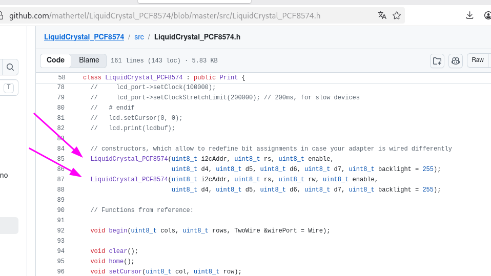
github.com/mathertel/LiquidCrystal_PCF8574/blob/master/src/LiquidCrystal_PCF8574.h LiquidCrystal_PCF8574 : public Print { // lcd_port->setClock(100000); // lcd_port->setClockStretchLimit(200000); // 200ms, for slow devices // endif lcd.setCursor
in „TWI1 auf Atmega328PB schlägt fehl“ · Mikrocontroller und Digitale Elektronik · · Screenshots
-
Datei
T6963c.c
for using with T6963cInit() //Macros for Bitbanging volatile unsigned char cmd_data=0; uint8_t readPCF8574A_DATA() { uint8_t ret_data=0; i2c_start_wait(PCF8574A_DATA_Address+1); ret_data=i2c_readNak(); i2c_stop(); return ret_data; } void writePFC8574A(uint8_t cmd, unsigned char data) { if (cmd) { i2c_start_wait(PCF8574A_CMD_Address+0); } else { i2c_start_wait(PCF8574A_DATA_Address+0); } i2c_write(data); i2c_stop(); } void T6963C_RESET_ENABLE() // T6963C_PORT_CTRL &= ~(1<<T6963C_RST) { cmd_data &= ~(1<<T6963C_RST
in „Problem mit T6963c bei Umstellung auf I2C“ · Mikrocontroller und Digitale Elektronik ·
-
Datei
PCF-Test-2a.c
/* * Test eines PCF8574A: reagiert er auf die Eingabe seiner Adresse mit Ack? * Bei erhaltenem Ack sollte die eine, bei nicht erhaltenem Ack die andere LED * blinken. * * Hardware: Board mit Atmega 644P und PCF8574A. Der PCF8574A ist mit SDA und SCL * gem. Manual verbunden - mit 10-k-Pullups. */ #include <util/twi.h> #include <avr/io.h> #include <util/delay.h> #include <i2cmaster.h> #define SCL PC0 // für PCF8574A #define
in „Software-TWI: enge Clock-Frequenz oder beliebige Zeiten?“ · Mikrocontroller und Digitale Elektronik ·
-
Datei
ATMEGA328P_Test.bas
I2C Config Sda = Portb.1 'SDA I2C Config I2cdelay = 1 'Wert für I2C-Port Dim _lcd_e As Byte Const Pcf8574_lcd = 78 'Address of I2C-LCD = 78 Enable Interrupts Config Int0 = Falling 'Int signal from PCF8574_KBD is connected to INT0 Const PCF_D4 = 4 ' Pin assignments for connection PCF8574 to LCD Const PCF_D5 = 5 Const PCF_D6 = 6 Const PCF_D7 = 7 Const PCF_RS = 0 Const PCF_RW = 1 Const PCF_E2 = 3 Const PCF_E1 = 2 '_lcd_e = 128 select E1, 64 select E2, 192 select both (for CLS or DefLCDChar etc.) _lcd_e
in „BASCOM AVR YwRobot_Lcd_i2c.lib für 1602 LCD anpassen“ · Mikrocontroller und Digitale Elektronik ·
-
PDF
Elektronik_Sortimente.pdf
2-Wire Serial EEPROM (AT24C32) ggf in DS3231 enthalten 3x Clock and calendar with 240 x 8-bit RAM (PCF8583) 5-10x 16-channel, 12-bit PWM Fm+ I2C-bus LED controller (PCA9685) 5x 16 CHANNEL LED DRIVER WITH DOT CORRECTION AND GRAYSCALE PWM CONTROL (TLC5940NT) 5x 8-bit I/O expander for I2C-bus (PCF8574, PCA8574, PCA8574A) 5x 16-Bit I/O Expander with Serial Interface (MCP23017) 20x Remote 8-bit I/O expander for I2C-bus (PCF8574) 10x Remote 8-bit I/O expander for I2C-bus (PCF8574A) 10x 8-bit A/D and D/A converter
in „Einkaufsliste für die Einrichtung eines Elektronik-Labors“ · Mikrocontroller und Digitale Elektronik ·
-
Datei
_3_I2C_Routinen.asm
PINB .equ SCLREAD = PINB .equ SCL = 0 ; Pin für Serial Clock .equ SDA = 1 ; Pin für Serial Data .equ PCF8574W = 0x40 ; Porterweiterung, Systemadresse des PCF8574 -> 0100 000 0 = 40 hex = 64 dez, Schreibmodus .equ PCF8574R = 0x41 ; Porterweiterung, Systemadresse des PCF8574 -> 0100 000 1 = 41 hex = 65 dez, Lesemodus .equ PCF8573W = 0xD0 ; Real Time Clock, Systemadresse des PCF8573 -> 1101 000 0 = D0 hex =208 dez, Schreibmodus .equ PCF8573R = 0xD1 ; Real Time Clock, Systemadresse des PCF8573 -> 1101 000 1 = D1 hex =209 dez
in „I2C Read Byte Problem in ASM“ · Mikrocontroller und Digitale Elektronik ·
-
Datei
LCDI2C.bas
Starte ' Subroutine to initialise the LCD-display Sub Lcd_init I2cstop Waitms 100 I2cstart I2cwbyte Pcf8574_lcd ' PCF8574A to LCD Waitms 30 '15 Call Lcd_reg(&H03) Waitms 6 '4 Call Lcd_reg(&H03) Waitus 200 'waitms 1 Call Lcd_reg(&H03) Waitms 6 '4 Call Lcd_reg(&H02) Waitms 1 Call Lcd_reg(&H02) Call Lcd_reg
in „Bascom LCD an I2C AN118“ · Mikrocontroller und Digitale Elektronik ·
-
Datei
tastatur_dfplayer_display.ino
FPSerial softSerial DFRobotDFPlayerMini myDFPlayer; void printDetail(uint8_t type, int value); // PCF8574 für Tastatur (I2C-Adresse: 0x20) #define PCF8574_ADDR 0x20 // Tasten-Matrix char keys[4][4] = { {'1', '4', '7', '*'}, {'2', '5', '8', '0'}, {'3', '6', '9', '#'}, {'A', 'B', 'C', 'D'} }; // Pin-Zuordnung PCF8574 <-> 4x4-Tastatur const int COLUMN_PINS[4] = {0, 1, 2, 3}; // P0-P3 als Spalten const int ROW_PINS[4] = {4, 5, 6, 7}; // P4-P7 als Reihen void setup() { Serial.begin(9600); FPSerial.begin(9600);
in „ESP8266 mit SPI Display und DF Player“ · Mikrocontroller und Digitale Elektronik ·
-
Datei
config_328.h
HD44780 */ #define LCD_TEXT /* character display */ #define LCD_PCF8574 /* PCF8574 backpack */ #define LCD_I2C_ADDR 0x3f /* PCF8574's I2C address */ /* control and data lines */ #define LCD_DB_STD /* use standard pins 4-7 for DB4-7 */ #define LCD_DB4 PCF8574_P4 /* port pin used for DB4 */ #define LCD_DB5 PCF8574_P5 /* port pin used for DB5 */ #define LCD_DB6 PCF8574_P6 /* port pin used for DB6 */ #define LCD_DB7 PCF8574_P7 /* port pin used for DB7 */ #define LCD_RS PCF8574_P0 /* port pin used for RS */
in „ComponentTester-1.42m problem“ · Mikrocontroller und Digitale Elektronik ·
-
Datei
config_328.h
HD44780 */ #define LCD_TEXT /* character display */ #define LCD_PCF8574 /* PCF8574 backpack */ #define LCD_I2C_ADDR 0x3f /* PCF8574's I2C address */ /* control and data lines */ #define LCD_DB_STD /* use standard pins 4-7 for DB4-7 */ #define LCD_DB4 PCF8574_P4 /* port pin used for DB4 */ #define LCD_DB5 PCF8574_P5 /* port pin used for DB5 */ #define LCD_DB6 PCF8574_P6 /* port pin used for DB6 */ #define LCD_DB7 PCF8574_P7 /* port pin used for DB7 */ #define LCD_RS PCF8574_P0 /* port pin used for RS */
-
PDF
TWI_USI_master_slave_120303.pdf
Ergänzungen vornehmen - und dieArbeit läuft fast von selbst. Als Beispiel: Um ein "0x55" an einen PCF8574 mit der TWI-Adresse "0x40" zu senden: twi_buffer[0] = 0x40; twi_buffer[1] = 0x55; TWI_MA_Write(twi_buffer, 2); Um den Status des PCF8574 anschließend zur Kontrolle wieder auszulesen: TWI_MA_Read
in „TWI-Master für ATMEGA in C (ohne TWI-Start/Stop, ACK/NACK)“ · Projekte & Code ·
-
Datei
conradlcd.c
COMMAND_MASK 0b00000000 #define DATA_MASK 0b00100000 #define INIT_4BIT_MODE 0b00000010 void write_to_pcf8574(char data) { i2c_write(data); _delay_us(40); i2c_write(data | ENABLE_MASK); _delay_us(40); i2c_write(data & DISABLE_MASK); _delay_us(40); } void write_byte(char data, char mask) { //write the high nibble first... char nibble = mask | ((data & 0xF0) >> 4); write_to_pcf8574(nibble); //...then the low nibble nibble = mask | (data & 0x0F); write_to_pcf8574(nibble); } void write_command(char data) { write_byte(data, COMMAND_MASK); } void write_data(char data) { write_byte
in „Conrad I2C LCD Modul“ · Mikrocontroller und Digitale Elektronik ·
-
Datei
lcdpcf8574.h
/* lcdpcf8574 lib 0x01 copyright (c) Davide Gironi, 2013 Released under GPLv3. Please refer to LICENSE file for licensing information. References: + based on lcd library by Peter Fleury http://jump.to/fleury */ #
in „Eclipse Kompilierung LCD Buchstabensalat“ · Mikrocontroller und Digitale Elektronik ·
-
Datei
I2C_Kon.c
unsigned char ucSlaveAdr, ucReadValue; unsigned char ucI2CStatus = NO_INFO; main() { unsigned char ucPCF8574Val; P1M1 |= 0x0C; // SDA und SCL als Open-Drain P1M2 |= 0x0C; I2SCLH = 19; // I2C-Geschwindigkeit ~100 KHz I2SCLL = 19; I2CON = 0x44; // I2C-Hardware aktivieren (STO,STA,SI=0, ) EI2C = 1; // I2C
in „I2C Interrupt“ · Mikrocontroller und Digitale Elektronik ·
-
Datei
I2Ckpl0.c
Probleme gemacht. Zugeben, CLCK-Bits sind nicht angepaßt, aber das ist hier nicht das Problem, da der PCF8574 ja antwortet nach dem Sprung zu blink(...) und das while(...) ist ja eigentlich eine Endlosschleife ohne Zeitprobleme. Dieses Problem war schon in der ersten Fassung vorhanden, die ansonsten aber
in „Wie avr-gcc starten?“ · Mikrocontroller und Digitale Elektronik ·
-
Datei
M16_TWI.c
/* TWI Test ATMega16 Quarz 8MHz LCD an PortC[2..7] und PortD7 PCF8574P: A[0..2] an Vcc 8x Low_Current LED; Port=>Masse Interne Pullups für TWI LCD_Backlight geschaltet über PORTA0 */ #ifndef F_CPU #define F_CPU 8000000UL #endif #define LCD_BL_OFF (PORTA &= ~(1<<PA0
in „AVR Problem mit TWI / PCF8574P“ · Mikrocontroller und Digitale Elektronik ·
-
Datei
I2C_display.h
// Pollin-Bausatz LCD zu I²C mit PCF8574 // RS Low - Steuerbefehl // RS=High Ascii ab Adresse-0x80=1.Zeile + 1.Spalte #include <avr/io.h> #include <stdlib.h> //#include "display.h" // für alle Display bis 4x20 #include <util/delay.h> #
in „LCD 4x40 ansteuern über PCF8574 (I2C)“ · Mikrocontroller und Digitale Elektronik ·
-
Datei
i2c.c
********************************************************************************/ I2C_ERRCODE WritePCF8574(I2C_DATA device, I2C_DATA dataByte) { I2C_ERRCODE ec; ec = Start(); if(ec) goto func_end; ec = TransmitSlaveAddressW(I2C_DEVICE_PCF8574+device); if(ec) goto func_end; ec = TransmitData(dataByte)
in „I2C Probleme beim starten“ · Mikrocontroller und Digitale Elektronik ·
-
PDF
TWI_Multi_Master_120315.pdf
Test 3 Drei Master senden unterschiedliche Daten (#8: "21+22", #16: "41+42", #32: "81+82") an einen PCF8574. Erwartungsgemäß folgen die Übertragungen nacheinander A B C D E F G H I J K L M N O P Q 8 18 28 28 Start, Master-Transmitter #08 8 18 28 28 #16 8 18 38 8 18 28 28 #32 8 18 38 8 18 28 28 Master