-
Datei
Einschalt_Verz.asm
runtergeladen und hinzugefügt ;*********************************************************** ; Hardware: PIC 16F628 ; Testplatine 18Pin ; 4MHz-Quarz ; 8xLED rot + 8xVorwiderstand 4k7 Ohm ;*********************************************************** ; Aufgabe: LEDs werden nacheinander eingeschaltet und bleiben
in „Achtung: Anfänger! PIC16F628 Fehlermeldung beim Assemblieren“ · Mikrocontroller und Digitale Elektronik ·
-
PDF
Usermanual_VM111_D.pdf
RS232-Port. (Kabel nicht mitgeliefert, z.B. CW014). · Unterstützt diese FLASH Mikrocontrollers: · PIC12F629, PIC12F675, PIC16F83, PIC16F84(A), PIC16F871, PIC16F872, · PIC16F873, PIC16F874, PIC16F876, PIC16F627(A),PIC16F628(A),PICF630, ….* · Abmessungen: 145 mm x 100 mm. (*)An updated list and software
in „Empfehlungen für einen PIC16F84 Bausatz“ · Mikrocontroller und Digitale Elektronik ·
-
PDF
SchreibtischSteuerung_Rev1.1.pdf
RB4/PGM 11 4 3 7 I6 O6 10 A1 + K3 GND B RES1 R2 10k 15 RA5/MCLR/VPP RB5 12 100k 8 I7 O7 9 P M2 +5V B 16 RA6/OSC2/CLKOUT RB6/T1OSO/T1CKI/PGC 13 RN3B GND CD+ A2 - 5 RA7/OSC1/CLKIN RB7/T1OSI/PGD ULN2003AD "AUF" 0 20,00K VSS 3 BU1 C1 C2 GND RETS-0915 S O 7 PIC16F628SO +15V 0 4 25 GND K3 K4 V GND A1 P T 1 3
in „Steuerung für höhenverstellbaren Schreibtisch“ · Projekte & Code ·
-
PDF
SchreibtischSteuerung_Rev1.1.pdf
RB4/PGM 11 4 3 7 I6 O6 10 A1 + K3 GND B RES1 R2 10k 15 RA5/MCLR/VPP RB5 12 100k 8 I7 O7 9 P M2 +5V B 16 RA6/OSC2/CLKOUT RB6/T1OSO/T1CKI/PGC 13 RN3B GND CD+ A2 - 5 RA7/OSC1/CLKIN RB7/T1OSI/PGD ULN2003AD "AUF" 0 20,00K VSS 3 BU1 C1 C2 GND RETS-0915 S O 7 PIC16F628SO +15V 0 4 25 GND K3 K4 V GND A1 P T 1 3
in „Höhenversllbarer Schreibtisch“ · Mikrocontroller und Digitale Elektronik ·
-
Datei
tastertolcd.asm
; This file is a basic code template for assembly code generation * ; on the PIC16F628A. This file contains the basic code * ; building blocks to build upon. * ; * ; If interrupts are not used all code presented between the ORG * ; 0x004 directive and the label main can be removed
in „Quarz auf Funktionalität testen?“ · Mikrocontroller und Digitale Elektronik ·
-
Datei
verlinkung.txt
+ * PIC16F1937 - - PIC16F1938 - - PIC16F1939 - - PIC16F1946 - - PIC16F1947 - - PIC16F505 - - PIC16F506 - - PIC16F526 - - PIC16F527 - - PIC16F54 - - PIC16F57 - - PIC16F59 - - PIC16F610 - - PIC16F616 - - PIC16F627A - - PIC16F628A - - PIC16F630 - - PIC16F631 - - PIC16F636 - - PIC16F639 - - PIC16F648A - - PIC16F676 - - PIC16F677 - - PIC16F684 - - PIC16F685 - - PIC16F687 - - PIC16F688 - - PIC16F689 - - PIC16F690 - - PIC16F707
in „MC PIC - Warum diese Ungleichbehandlung?“ · Mikrocontroller und Digitale Elektronik ·
-
PDF
PIC16F628A_mit_Servo_-_Neue_Schaltung.pdf
Vellemann – Netzteil; 12V (Masse direkt an PIC VSS; 5V) Ansatz: Labor – Netzteil; 6,4V (Masse an Spannungsregler Masse; 5V) PIC generiert Schleifen, die von 1ms bis 2ms VSS PIC16F628A VDD in x+0,083ms PIC RB1 Schritten steigen. VDD Nach jedem Schritt
in „PIC16F628A PWM mit delay (ASM)“ · Mikrocontroller und Digitale Elektronik ·
-
Datei
frq_TM1637.asm
list p=16f628a ;************************************************************** ; PLJ-6LED-A - ca. 20Hz - 500kHz ;************************************************************** ;********************************
in „Frequenzzähler 1Hz-100khZ“ · Mikrocontroller und Digitale Elektronik ·
-
 Bild
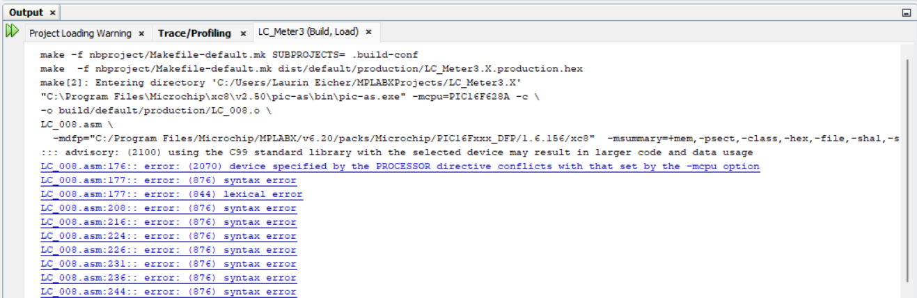
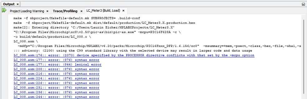
Compiler-Fehlermeldungen in einer Entwicklungsumgebung
make -f nbproject/Makefile-default.mk SUBPROJECTS=.build-conf make -f nbproject/Makefile-default.mk dist/default/production/LC_Meter3.X.production.hex make [2]: Entering directory 'C:\Users\Laurin Eicher\MPLABXProjects\LC_Meter3.X' "C:\Program Files\Microchip\MPLABX\v6.20\pic-as\bin\pic-as.exe" -mcpu=PIC16F628A -c \ -o build/default/production/LC_008.o \ -mdfps="C:\Program Files\Microchip\MPLABX\v6.20\packs\Microchip\PIC16Fxxx_DFP\1.6.156\xc8" -msummary=+mem, -psect, -class
in „Kann assembler file nicht builden“ · Mikrocontroller und Digitale Elektronik · · Screenshots
-
Datei
PROJECT.H
////////////////////////////////// // Datei: Project.h // // Setzt voraus folgende Pinbelegung von PIC16F628(4MHz): // PIC: LCD: // //(PORTA.0 Input) //(PORTA.1 Vref) // PORTA.2 E // PORTA.3 MCLR-Funktion (=1 immer) // PORTA.4 Quarzanschluss // PORTA.5 Quarzanschluss // // PORTC.0 DB4 // PORTC.1 DB5
in „PIC16F676 LCD_Init“ · Mikrocontroller und Digitale Elektronik ·
-
Datei
test.asm
list p=16f628 list w=2 ;unterdrückt Warnungen ;************************************************************** ;* Test LED ein / aus ;* ;* PortB LEDs ;* ;********************************************************
in „PIC 16F628 Problem mit LEDs“ · Mikrocontroller und Digitale Elektronik ·
-
Datei
170227_628_SetLED.txt
[avrasm] ; TODO INSERT CONFIG CODE HERE USING CONFIG BITS GENERATOR ; PIC16F628A Configuration Bit Settings ; Assembly source line config statements #include "p16f628a.inc" ; CONFIG ; __config 0xFFFF __CONFIG _FOSC_INTOSCIO & _WDTE_OFF & _PWRTE_OFF & _MCLRE_ON & _BOREN_OFF
in „LED 3x blinken dann LED permanent ON“ · Mikrocontroller und Digitale Elektronik ·
-
Datei
Liste.txt
1x dm7400n GATE NAND 4CH 2-INP 14DIP 1x 7403 1266 1x FLH 291 ???????? 1x MM47C02N ?????? 1x 9316 PC/F7403 ?????? (Dip 16) 1x S7404 ????????? 3x PAL16R8DCN ???? 3x Tl082 JFET-Input Operational Amplifiers 5x NE555 Timer 7x 74F109N Positive J-K positive edge-triggered flip-flops 10x 74166N 16-pin DIP Shift Register 8x 74LS21 DUAL 4-INPUT AND GATE 10x 74F10N Triple 3-Input Positive-NAND Gates 2x PIC 18F458-I - P: MCU, PICmicro, 32 KB, 40 MHz, DIL-40 3x UVE 3130-10 ????? 5x Intel P8052AH Cpu 54x DESP10 ES2 Safe ware Controller 2x Pic16f628a Program Memory
-
Datei
lsg10tx_v2.asm
Tektquelle: 4 MHz ;************************************************************** ; Includedatei für den 16F628a einbinden #include <P16f628a.INC> ; Configuration festlegen ; interner 4MHz Oszillator. Sonstiger Unsinn aus. __CONFIG _PWRTE_ON & _WDT_OFF & _LVP_OFF & _INTRC_OSC_NOCLKOUT & _BODEN_OFF & _MCLRE_OFF
in „Leitungssuchgeräte - Funktionsweise / Selbstbau“ · Analoge Elektronik und Schaltungstechnik ·
-
PDF
CCP_Tricks.pdf
measure the period of an analog signal. Figure 6-1 shows an example circuit using the peripherals of the PIC16F684. FIGURE 6-1: CIRCUIT R2 PIC16F684 Analog R1 Input VSENSE VOUT CCP1 R3 VREF VTHR Comparator R4 (on-board PIC16F684) R3 and R4 set the threshold voltage for the comparator. When the analog input
in „Lüfter über PWM, Bauteilauswahl?!?“ · Mikrocontroller und Digitale Elektronik ·
-
Datei
IICTSUS.ASM
list p=16f628A ;************************************************************** ;* Pinbelegung ;* ---------------------------------- ;* PORTA: ;* 0 - ;* 1 CLK in ;* 2 SDA in ;* 3 - ;* 4 - ;* 5 - ;* 6 - ;* 7 - ;
-
Datei
Liste.txt
---------------------------------- 6X MSP430G2152IPW14R 13x MC68HC11A1MFN 8-Bit Microcontroller 4X PIC16F877A-I/T 4X AM1705BPTP4 YF-17AEVYW G4 538PTP 18X PEB 2085N 3X MC68HC11A1MFN F92J SZAU9603 18x PIC16C54 -RC/SO 9833SAN Microchip Pic16c54-lp/p 8bit CMOS MCU Dip18 2x LM3S2948-IQC50-A2 - MCU 32-bit
-
PDF
compactflashOnPicArticle.pdf
2-byte counter (858) 549-2531 www.ARMAnet.com on a cool little device. But, using those same basic PIC16F877 subroutines, the possibili- Microchip Technology, Inc. ties are endless. Want to (888) 628-6247 store a year’s worth of a (480) 786-7200 regularly sampled analog Fax: (480) 899-9210 signal? Put
in „COMPACT FLASH-Card“ · Mikrocontroller und Digitale Elektronik ·
-
PDF
compactflashOnPicArticle.pdf
2-byte counter (858) 549-2531 www.ARMAnet.com on a cool little device. But, using those same basic PIC16F877 subroutines, the possibili- Microchip Technology, Inc. ties are endless. Want to (888) 628-6247 store a year’s worth of a (480) 786-7200 regularly sampled analog Fax: (480) 899-9210 signal? Put
in „Indentify Drive bei CF-Karte“ · Mikrocontroller und Digitale Elektronik ·
-
Datei
lcd.asm
list p=16f628 ;************************************************************** ;* Pinbelegung ;* ---------------------------------- ;* PORTA: 0 O LCD Read / Write ;* 1 O LCD Register Select ;* 2 - ;* 3 - ;* 4 -
in „RS-232 empfangen mittles PIC16F628“ · Mikrocontroller und Digitale Elektronik ·
-
Datei
pk2cmdminus_supported_devices.txt
PIC12F509 Baseline 0x0000FFFF PIC12F510 Baseline 0x0000FFFF PIC12F519 Baseline 0x0000FFFF PIC16F54 Baseline 0x0000FFFF PIC16F57 Baseline 0x0000FFFF PIC16F59 Baseline 0x0000FFFF PIC16F505 Baseline 0x0000FFFF
in „Programmieren eine PIC18F2585 mir einem HEX-File“ · Mikrocontroller und Digitale Elektronik ·
-
Datei
ISR_Timer_Beispiel.ASM
;Hallo Norbert, ;Hier ein (unvollständiges) Beispiel für den 16F628 (u. andere midrange PICs) ;wie eine Interrupt-Service-Routine und die zur Zeitmessung zugehörige TMR0 ;Initialisierung beim aussehen könnte. ;Natürlich gehört noch einiges an Code "außen rum" dazu
in „Achtung: Anfänger! PIC16F628 Fehlermeldung beim Assemblieren“ · Mikrocontroller und Digitale Elektronik ·
-
Datei
HD44780.INC
; This file is succesful tested with ; PIC16F1827, PIC16F628/-A, PIC16F876/-77 ; PIC16F84 , ; LCD-Timing: Timing in LCD_Init is fine up to fosc 10MHz ; fosc >10MHz needs an other Sub "Delay1ms" for ; fosc in use ;****************************
in „Warum, geht die zweite Displayzeile nicht? PIC Assembler“ · Mikrocontroller und Digitale Elektronik ·
-
Datei
uvbel.asm
list p=16f628 errorlevel -302 ;unterdrückt Warnungen ;************************************************************** ;* Leiterplatten-UV-Belichtungsgerät ;* ;* ;* PORTA:0 Taster UP ;Zeit erhöhen ;* 1 Taster DOWN
in „nochmal PIC 16F628 EEprom“ · Mikrocontroller und Digitale Elektronik ·
-
Datei
HD44780.INC
Delay1ms for ; fosc in use ; ; Purpose; Initialize a HD44780-LCD ; This file is succesful tested with ; PIC16F1827, PIC16F628, PIC16F876 ;****************************************************************************** ; ; TO USE THIS FILE, PLEASE COPY IT TO YOUR PROJECT-FOLDER! ; ;*************************
in „PIC LCD Ausgabe von Strings“ · Mikrocontroller und Digitale Elektronik ·
-
Datei
HD44780.INC
; actual fosc in use ; ; Purpose; Initialize a HD44780-LCD ; This file is succesful tested with ; PIC16F1827, PIC16F628, PIC16F876 ;****************************************************************************** ; ; TO USE THIS FILE, PLEASE COPY IT TO YOUR PROJECT-FOLDER! ; ;*************************
in „Probleme mit LCD an PIC 16f887“ · Mikrocontroller und Digitale Elektronik ·
-
PDF
50-MHz-Quarztester.pdf
optional addition or subtraction of a frequency offset (programmable) • very low component count: a PIC 16F628, 5 7-segment LED displays, a 20MHz crystal and a few resistors • optional (configurable) power-saving mode which automatically turns the display off if the frequency didn't change significantly
-
Datei
HD44780.INC
HD44780-LCDs ; Succesful tested with ; PIC16F1827, PIC16F628/-A, PIC16F876/-77, PIC16F84 ; Timing: For the LCD ist timing fine up to fosc 32MHz. For exact ; timing in delays use the multiplicator "FOSC_MULT" ; e.g.: movlw .10*FOSC_MULT ; CALL
in „was genau ist eine library“ · Mikrocontroller und Digitale Elektronik ·
-
PDF
kicad_8450_dcm_liste_neu_v3.pdf
EEPROM, DIP18 PIC16(L)F628-xxI/SO 2048W Flash, 224B SRAM, 128B EEPROM, SO18 PIC16(L)F628-xxI/SS 2048W Flash, 224B SRAM, 128B EEPROM, SSOP20 PIC16(L)F628A-I/P 2048W Flash, 224B SRAM, 128B EEPROM, DIP18 PIC16(L)F628A-I/SO PIC16(L)F628A, 2048W Flash, 224B SRAM, 128B EEPROM, SO18 PIC16(L)F628A-I/SS PIC16(L)F628A, 2048W Flash, 224B SRAM, 128B EEPROM, SSOP20 PIC16(L)F648A-I/P 4096W Flash, 256B SRAM, 256B EEPROM, DIP18 PIC16(
in „KiCAD Eeschema, Bibliotheksdokumentation *.dcm als PDF-Datei“ · Platinen ·
-
Datei
ServoPWM.asm
Interne 4MHz Oszillator verwendet. ; ______ ; RA2-|O|__| |-RA1 ; RA3-| 1 |-RA0 ; RA4-| 6 |-RA7 ; RA5-| F |-RA8 ; VSS----| 6 |----VDD ;Signal ->RB0-| 2 |-RB7 ; RB1-| 8 |-RB6 ; RB2-| A |-RB5 ; RB3-|______|-RB4 ; ;Verwendet wird ein PIC16F628A ; ;Einen großen Dank an die Seite: ;http://www.piclist.com/techref
in „PIC16F628A PWM mit delay (ASM)“ · Mikrocontroller und Digitale Elektronik ·
-
Datei
tft.c
0x3b3b3bUL); /* light grey */ EVE_cmd_dl(DL_VERTEX_FORMAT); /* set to 0 - reduce precision for VERTEX2F to 1 pixel instead of 1/16 pixel default */ /* draw a rectangle on top */ EVE_cmd_dl(DL_BEGIN | EVE_RECTS); EVE_cmd_dl(LINE_WIDTH(1U * 16U)); /* size is in 1/16 pixel */ EVE_color_rgb(BLUE_1); EVE_cmd_dl
-
Datei
lamps_01.asm
SOFTWARE * ;************************************************************************** ;* Microchip PIC(tm) Programmer & experiment board * ;* DEMO2 program for testing K8048 with PIC16F627(A)! * ;* Generate 4 LED light effects, you can select these with SW1..4 * ;*************************************
in „Pic Lernen aber wie??“ · Mikrocontroller und Digitale Elektronik ·
-
Datei
Values.txt
2 Reset 2 REICHELT_VFI353 2 RECTIFIER-B40S 2 r9 2 PWR 2 PV8251 2 PR1003 2 Power Out 2 POWER 2 PIN3F061.120 2 PIC16F877P 2 PIC16F874P 2 PG203J 2 PCA82C250 2 P6KE200A 2 OPA2333 2 OPA1632 2 OP11P 2 Netz 2 NE567 2 NE555N 2 NE5532 2 MT48LC8M16A2 2 MSTBV3 2 MOSFET-P-4D-FDC604P 2 MOC3021 2 ML10 2 MEGA8L-P
in „[KiCad] Bibliotheksaufbau - Konzeptideen gesucht“ · Platinen ·
-
PDF
Schematic_Prints2.pdf
1 2 3 J VDD J1 C1 +5V GND 100uF V GND 5 J GND P1 U1 + 3 RB7 J2 2 14 VDD VSS 5 1 PGD 13 16 Header 3 12 RB7/T1OSI/PGD RA7/OSC1/CLKIN 15 RA7 CLKIN D1 P2 11 RB6/T1OSO/T1CKI/PGC RA6/OSC2/CLKOUT 4 RA6 CLKOUT TMBYV10-4 RB5 10 RB5 RA5/MCLR
in „MOSFET als Öffner/Schaltungsfehler“ · Analoge Elektronik und Schaltungstechnik ·
-
Datei
Devices.txt
PV8251 2 PINHD-2X3_2.54-SMD 2 PINHD-2X10 2 PINHD-1X7 2 PINHD-1X2/90 2 PINHD-1X1_2.54 2 PINHD-1X12 2 PIN3F061.120 2 PIC16F877P 2 PIC16F874P 2 PG203J 2 PCA82C250 2 PC817 2 OSZILLATOR 2 OPA2333 2 OPA1632 2 OP11P 2 NPN-TRANSISTOR_SOT23W 2 -NPN-TO92-ECB 2 -NPN-TO225AA 2 NPNSOT89 2 NPNSOT323 2 N-MOSFET-SO8 2 NE567
in „[KiCad] Bibliotheksaufbau - Konzeptideen gesucht“ · Platinen ·
-
Datei
LCD_Funktionen.c
LCD-Behandlungsrutinen. // für Pollin-LCD "HB10401" (4 Zeilen, je 10 Zeichen) // Setzt voraus folgende Pinbelegung von PIC16F628(4MHz): // PIC: LCD: // PORTC.0 DB4 // PORTC.1 DB5 // PORTC.2 DB6 // PORTC.3 DB7 // = BUSY-Flag // PORTC.4 RS // PORTC.5 R/W // // PORTA.0 Input // PORTA.1 Vref // PORTA.2 E // // PORTA.3 MCLR-Funktion
in „PIC16F676 LCD_Init“ · Mikrocontroller und Digitale Elektronik ·
-
 Bild
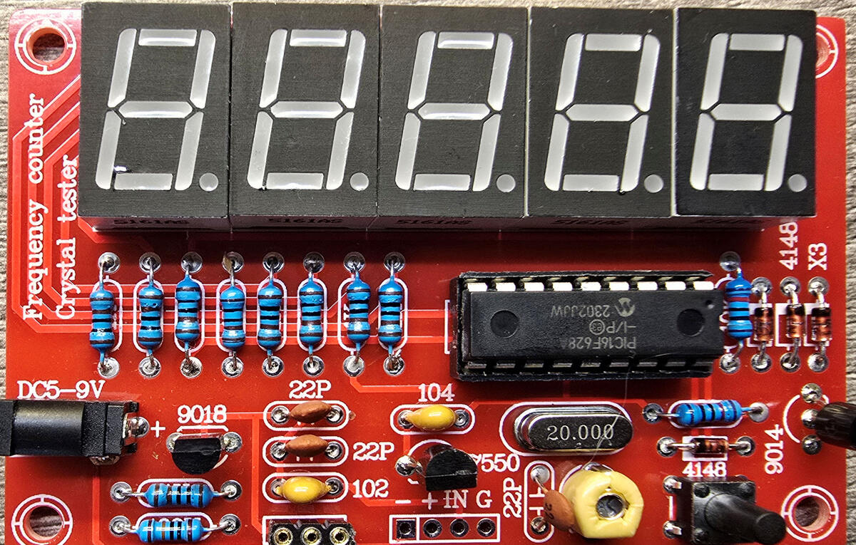
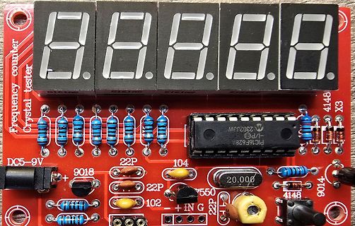
Frequenzzähler mit Kristalltester und 7-Segment-Anzeige
Frequency counter Crystal tester PIC16F628A 20.000 DC5-9V 9018 22P 104 102 4148 X3 9014
in „Quarz-Tester mit PIC16F628“ · Mikrocontroller und Digitale Elektronik · · Platinenfotos
-
 Bild
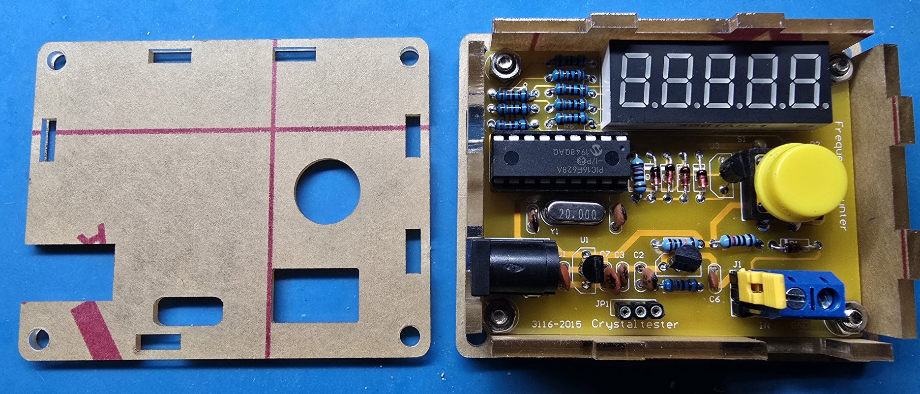
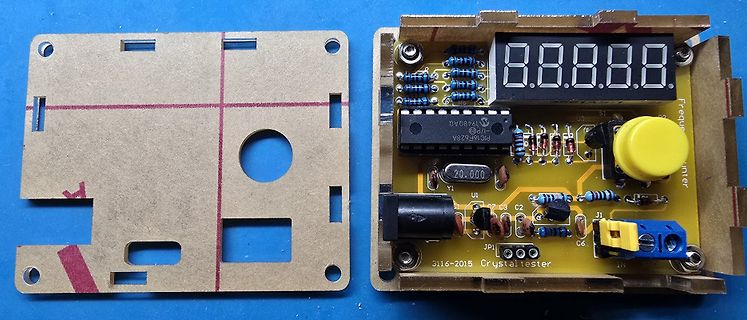
Leiterplatte eines Frequenzzählers mit 7-Segment-Anzeige
8.8.8.8.8. Y1 20.000 U1 PIC16F628A C3 C2 C6 JP1 3116-2015 Crystalltester
in „Quarz-Tester mit PIC16F628“ · Mikrocontroller und Digitale Elektronik · · Platinenfotos
-
 Bild
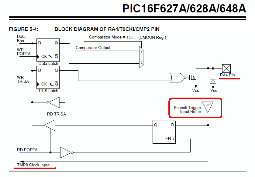
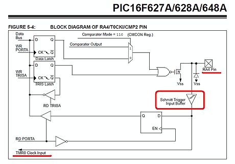
Blockschaltbild des RA4/T0CKI/CMP2 Pins eines PIC-Mikrocontrollers
PIC16F67A/628A/648A FIGURE 5-4: BLOCK DIAGRAM OF RA4/T0CKI/CMP2 PIN Comparator Mode = 110 (CMCON Reg.) Comparator Output Data Latch TRIS Latch RA4 Pin Schmitt Trigger Input Buffer Vss RD TRISA RD PORTA
in „Induktiver Positionssensor - Fragen dazu“ · Mikrocontroller und Digitale Elektronik · · Diagramme
-
Datei
wechselbl.asm
RXXX ; ;BESCHREIBUNG: LAESST ZWEI LED'S AN PORTA0 UND PORTA1; ; ABWECHSELND BLINKEN ; ;PROZESSORTYP: PIC16F628 ; ;=====================================================; ;VARIABLEN DEFINIEREN STATUS equ 03h TRISA equ 85h PORTA equ 05h C1 equ 20h C2 equ 21h ;PORTS DEFINIEREN bsf STATUS,5 ;WECHSEL ZU BANK1
in „Frage zu Assembler und Quellcode“ · Mikrocontroller und Digitale Elektronik ·
-
PDF
device.pdf
MPU/MCU PIC16F628 NONE No Need WPIC2 V5.41 MICROCHIP MPU/MCU PIC16F628A NONE No Need WPIC2 V5.41 MICROCHIP MPU/MCU PIC16F630 NONE No Need WPIC2 V5.41 MICROCHIP MPU/MCU PIC16F636 NONE No Need WPIC2 V5.41 MICROCHIP
-
Datei
Untitled_PROBEE.asm
list p=16f628a ; Definition des PICŽs #include <P16f628a.INC> ; Laden der jeweiligen include Datei für den PIC ERRORLEVEL -302 loops equ 0x20 ; Wartezeit für WAIT in Millisekunden loops2 equ 0x21 ; interner timer
in „EA DOG M162W-A“ · Mikrocontroller und Digitale Elektronik ·
-
Datei
Programm_EADOGP.asm
list p=16f628a ; Definition des PICŽs #include <P16f628a.INC> ; Laden der jeweiligen include Datei für den PIC ERRORLEVEL -302 loops equ 0x20 ; Wartezeit für WAIT in Millisekunden loops2 equ 0x21 ; interner timer
in „EA DOG M162W-A“ · Mikrocontroller und Digitale Elektronik ·
-
Datei
1_dht11.c
/* Project: Temperature and humidity measurements using DHT11 MCU: PIC16F628A Clock: 4.0MHz external resonator MCLR is enabled Date: Jan 10, 2012 Written by: Rajendra Bhatt (www.embedded-lab.com) */ // LCD module connections sbit LCD_RS at RB4_bit; sbit LCD_EN at RA4_bit
in „Feuchtigkeitsmessung DHT11 PIC16F690 - Hilfe C-Cde gesucht-“ · Mikrocontroller und Digitale Elektronik ·
-
Datei
TECHLIB_APR07_Dir.txt
16:38 220.386 t13_G0107s.pdf 12.03.2007 16:38 756.214 t15_F0605.pdf 12.03.2007 16:38 127.741 t15_F0605s.pdf 12.03.2007 16:38 2.142.597 t2313_I0406.pdf 12.03.2007 16:38 177.671 t2313_I0406s.pdf 12.03.2007 16:38 2.330.349 t24_44_84_F0207.pdf 12.03.2007 16:38 296.786 t24_44_84_F0207s.pdf 12.03.2007 16:38 2.498.284 t25_45_85_J1206.pdf 12.03.2007 16:38 253.733 t25_45_85_J1206s.pdf 12.03.2007 16:38 1.484.845
in „STK500 CD ISO Image“ · Mikrocontroller und Digitale Elektronik ·
-
Datei
devlist.txt
5675 D1 PIC16C61 . . . .1) 6038 D1 PIC16C620 . . . .1) 6039 D1 PIC16C621 . . . .1) 6040 D1 PIC16C622 . . . .1) 6041 D1 PIC16C62 . . . .1) 6042 D1 PIC16C62A . . . .1) 6318 D1 PIC16C63 . . . .1) 6290 D1 PIC16C64
in „PROM lesen /schreiben / Programmiergerät“ · Mikrocontroller und Digitale Elektronik ·
-
Datei
Klingel.asm
include p16f628.inc cblock 0x20 Delay1 bz1 Temp TonHoehe TonDauer MelEnd MelodieNummer AdrL AdrH STimer0 TempStatus TempFsr TempPclath TempW Flags endc #define _TonOff Flags,0 #define _MelTableEnd Flags,1 #define
-
PDF
DCC_Laborbooster.pdf
11 12 nach dem Einschalten: 13 -Spannung (die DCC-Spannung vor der H-Brücke) 14 -ohne Untermenü 15 16 -Fahrstufe 17 -0...127 (für DCC und Analog) 18 -ENTER => zurück ins Haupmenü 19 20 -Funktion (Lokdekoder, Multifunktionsdekoder) 21 -FL/F1/F2/F3/F4 22 -AUS/EIN 23 -ENTER => zurück ins Haupmenü 24 25
-
PDF
217369.pdf
) f 1.100 .400 .500 2.100 O 22 (27,94) (10,16) (12,70) 42 (53,34) i 1.200 .300 .400 2.400 a 24 (30,48) (7,62) (10,16) 48 (60,96) 1.200 .400 .500 3.200 .900 1.000 0 24 (30,48) (10,16) (12,70) 64 (81,28) (
in „Kühlkörper TO3 Befestigungslöcher zu groß?“ · Mechanik, Gehäuse, Werkzeug ·
-
Datei
Shorttimer.c
*********** //** //** File name: Shorttimer.c //** Generated by: //** Date: Sunday, March 13, 2011 16:24:07 //** //** ************************************************************************************ #define MX_PIC //Definitionen für Microcontroller #define P16F628A #define MX_EE #define MX_EE_TYPE1
in „LED Ausgabe in eine Zählschleife integrieren ohne Zeit zu verlieren“ · Mikrocontroller und Digitale Elektronik ·