-
 Bild
Bild
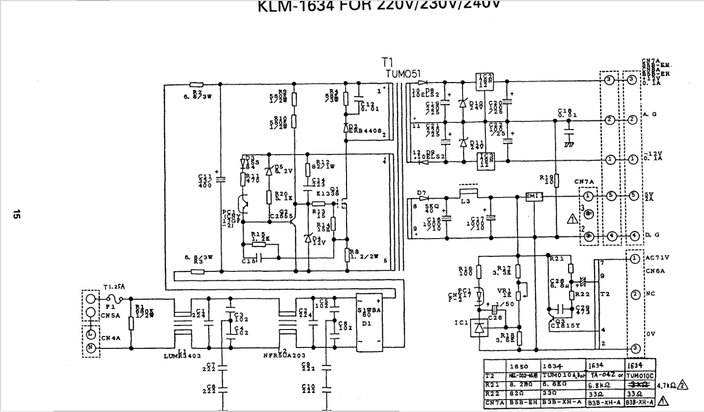
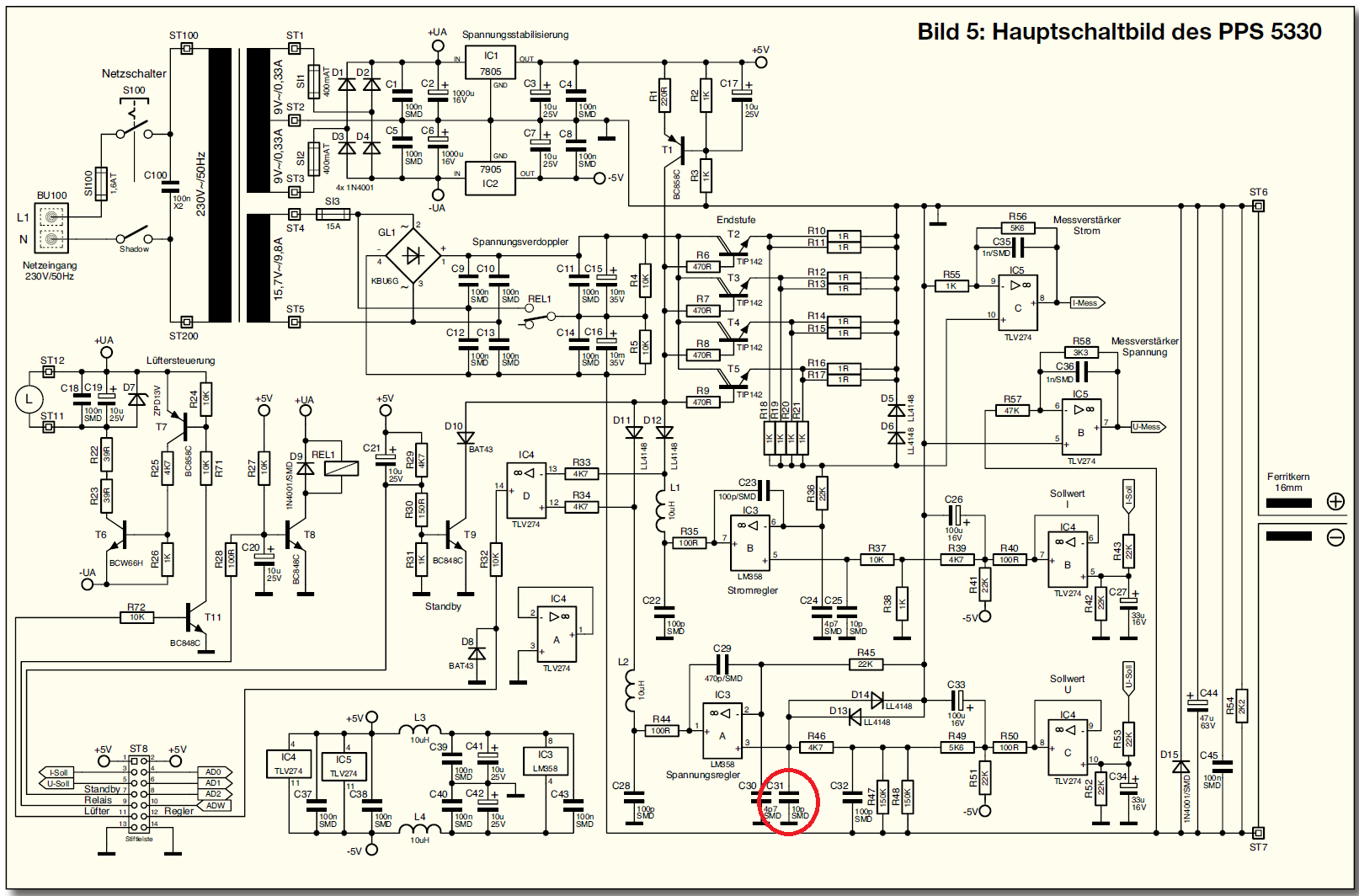
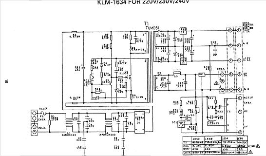
Schaltplan eines Netzteils
82 83 84 85 86 87 88 89 90 91 92 93 94 95 96 97 98 99 100 101 102 103 104 105 106 107 108 109 110 111 112 113 114 115 116 117 118 119 120 121 122 123 124 125 126 127 128 129 130 131 132 133 134 135 136 137 138 139 140 141 142 143 144 145 146 147 148 149 150 151 152 153 154 155 156 157 158 159 160 161
-
Thread
Welche Portnummer für UDP-Übertragung?
Ports vermerkt. Diese gibt es schon, nennt sich rpcbind (früher portmapper), die hört auf Port 111 (UDP und TCP). Dafür muss man sich dann statt der Portnummer eine Programmnummer ausdenken zum Registrieren. ;-)
-
Thread
Anfängerfrage: AM vs FM und CC1101
#include <ELECHOUSE_CC1101_SRC_DRV.h> int gdo0; byte transmitt_byte[11] = {72,101,108,108,111,32,87,111,114,108,100}; char *transmitt_char = "Hello World"; void setup() { #ifdef ESP32 gdo0 = 2; // for esp32! GDO0 on GPIO pin 2. #elif ESP8266 gdo0 = 5; // for esp8266! GDO0 on pin
-
 Bild
Bild
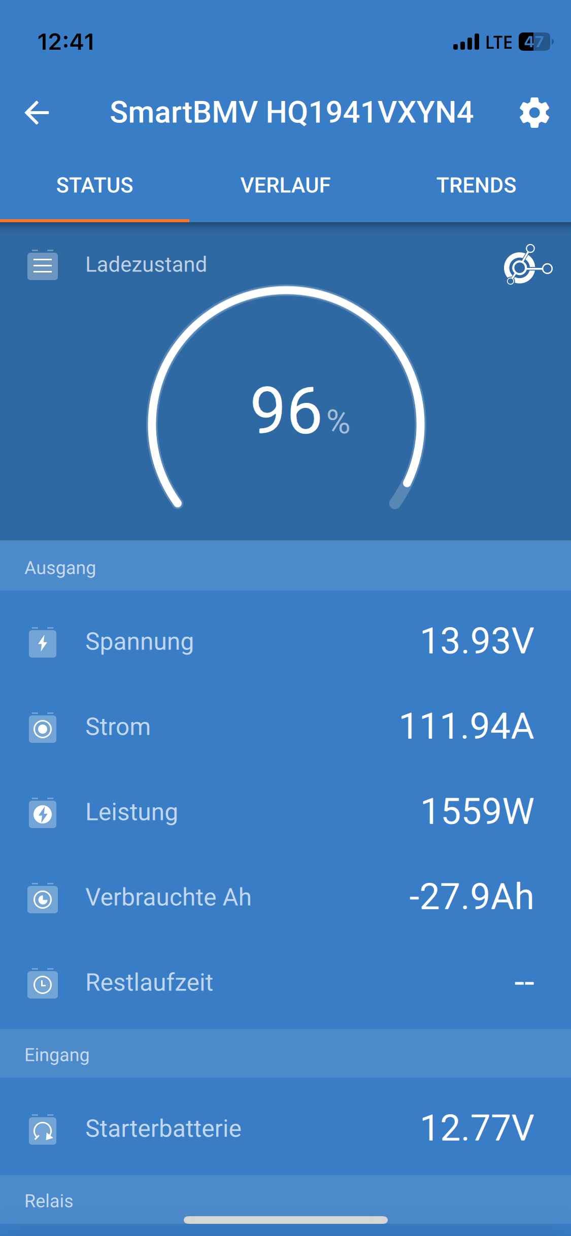
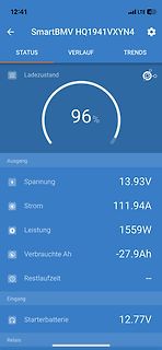
App-Screenshot eines Batterie-Monitoringsystems
41 LTE 47 SmartBMV HQ1941VXYN4 STATUS VERLAUF TRENDS Ladezustand 96% Ausgang Spannung 13.93V Strom 111.94A Leistung 1559W Verbrauchte Ah -27.9Ah Restlaufzeit -- Eingang Starterbatterie 12.77V Relais
-
 Bild
Bild
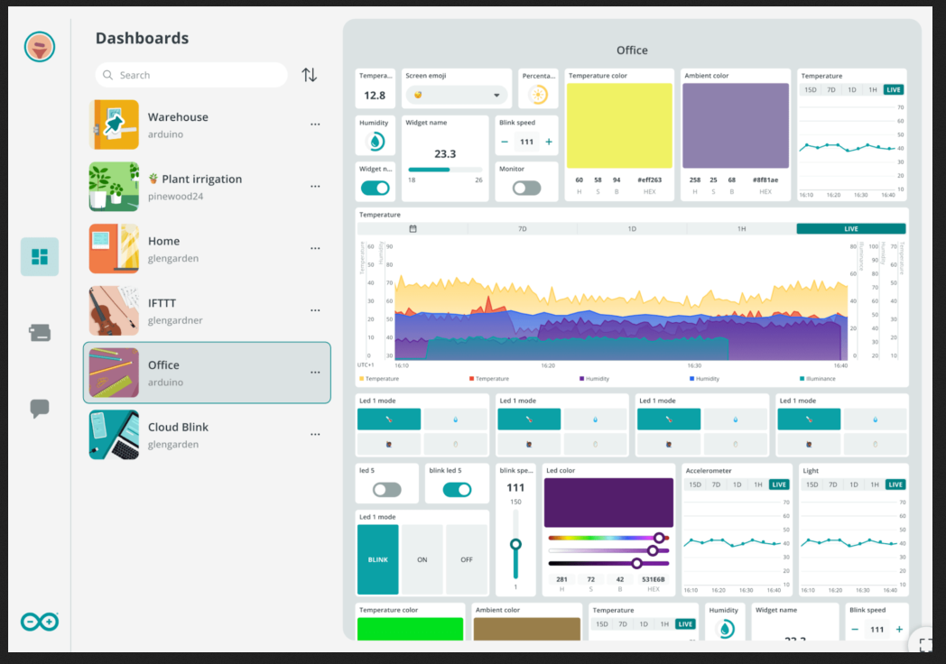
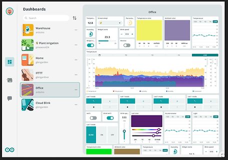
Dashboard einer IoT-Überwachungssoftware
40 30 20 10 0 UTCv1 16:10 16:20 16:30 16:40 Led 1 mode Led 1 mode Led color Accelerometer Light 150 111 15D 7D 1D 1H LIVE 15D 7D 1D 1H LIVE blink led 5 Led 1 mode blink spe... 111 Temperature color Ambient color Temperature 15D 7D 1H LIVE Humidity Widget name Blink speed 111
-
 Bild
Bild
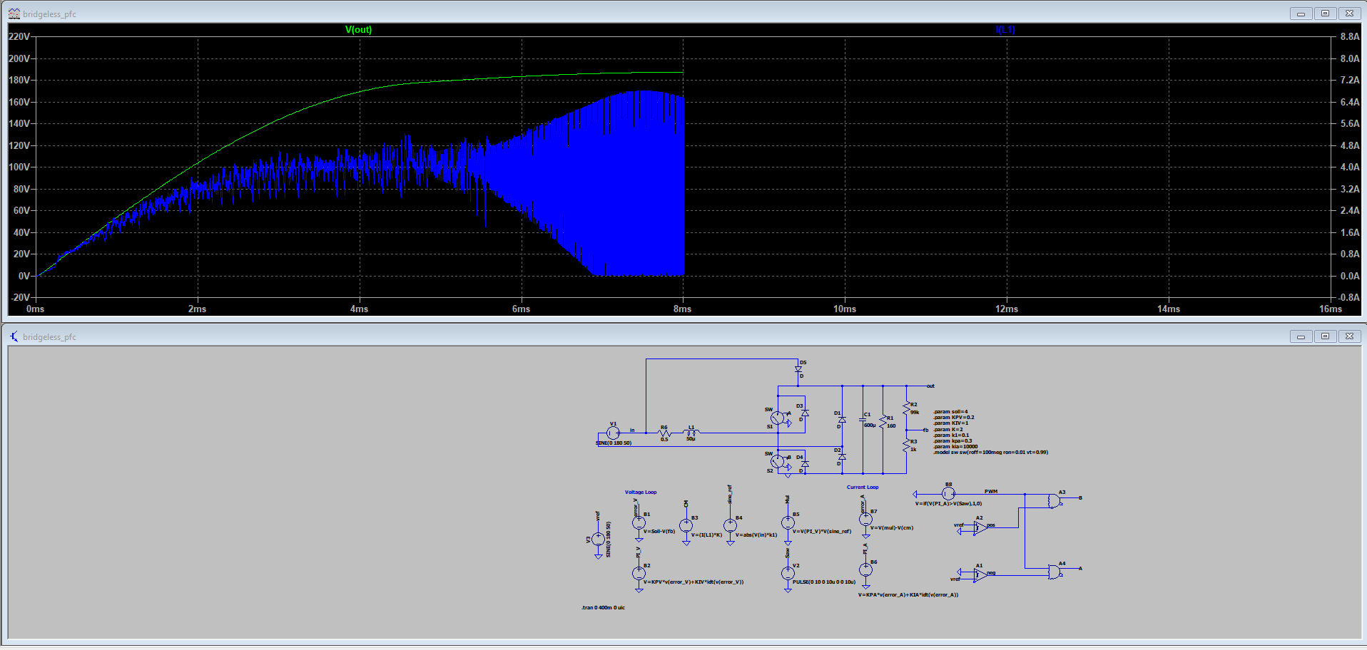
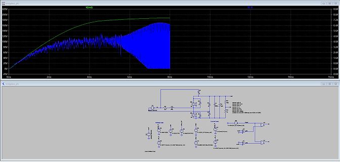
Simulationssoftware mit Oszillogramm und Schaltplan
R89 R90 R91 R92 R93 R94 R95 R96 R97 R98 R99 R100 R101 R102 R103 R104 R105 R106 R107 R108 R109 R110 R111 R112 R113 R114 R115 R116 R117 R118 R119 R120 R121 R122 R123 R124 R12
-
Thread
uint8_t auf int16_t erweitern
jetzt nicht klappt, das Beispiel: [c] //... const uint8_t anzArray[] PROGMEM={64,76,84,92,98,104,111,120,132,161,190}; volatile int16_t z; z = anzArray[i+1] - anzArray[i]; // oder auch z = (int16_t)(anzArray[i+1]&0x00ff) - (int16_t)(anzArray[i]&0x00ff); [/c] Letzteres liefert im Microchip
-
 Bild
Bild
-
 Bild
Bild
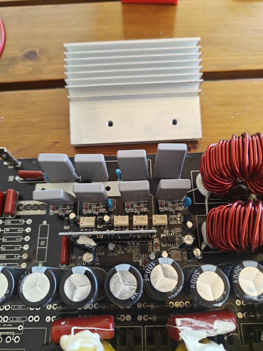
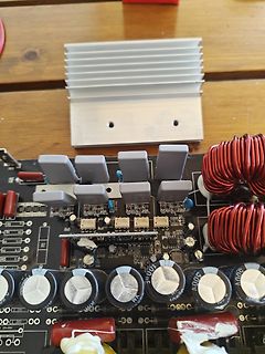
Leiterplatte eines Netzteils mit Kühlkörper und Spulen
500V, 051, 053, R5, R2, R1, 100, 101, 102, 103, 104, 105, 106, 107, 108, 109, 110, 111, 112, 113, 114, 115, 116, 117, 118, 119, 120, 121, 122, 123, 124, 125, 126, 127, 128, 129, 130, 131, 132, 133, 134, 135, 136, 137, 138, 139, 140, 141, 142, 143, 144, 145, 146, 147, 148, 149, 150, 151
-
 Bild
Bild
Tabelle mit Zahlenwerten und Eingabefeld
82 83 84 85 86 87 88 89 90 91 92 93 94 95 96 97 98 99 100 101 102 103 104 105 106 107 108 109 110 111 112 113 114 115 116 117 118 119 120 121 122 123 124 125 126 127 128 129 130 131 132 133 134 135 136 137 138 139 140 141 142 143 144 145 146 147 148 149 150 151 Antwort: 100
-
 Bild
Bild
-
 Bild
Bild
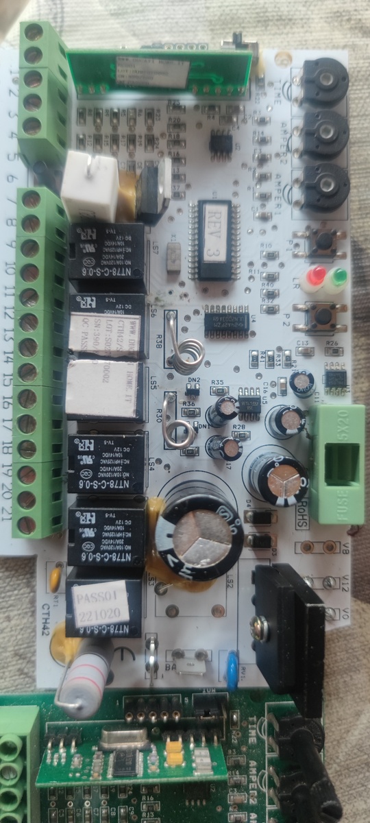
Foto einer bestückten Leiterplatte mit Relais und Bauteilen
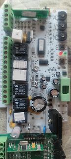
, C94, C95, C96, C97, C98, C99, C100, C101, C102, C103, C104, C105, C106, C107, C108, C109, C110, C111, C112, C113, C114, C115, C116, C117, C118, C119, C120, C121, C122, C123, C124, C125, C126, C127, C128, C129, C130, C131, C132, C133, C134, C135, C136, C137, C138, C1
-
 Bild
Bild
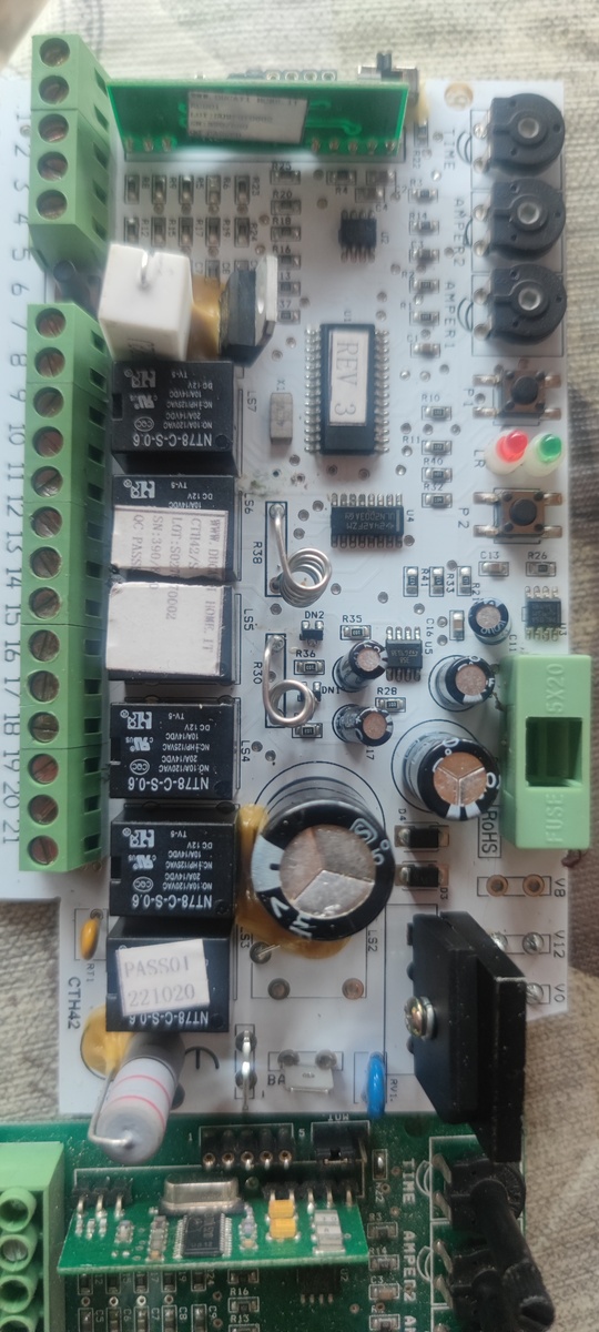
Foto einer bestückten Leiterplatte mit Relais und Bauteilen
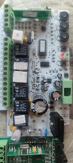
, C94, C95, C96, C97, C98, C99, C100, C101, C102, C103, C104, C105, C106, C107, C108, C109, C110, C111, C112, C113, C114, C115, C116, C117, C118, C119, C120, C121, C122, C123, C124, C125, C126, C127, C128, C129, C130, C131, C132, C133, C134, C135, C136, C137, C138, C1
-
 Bild
Bild
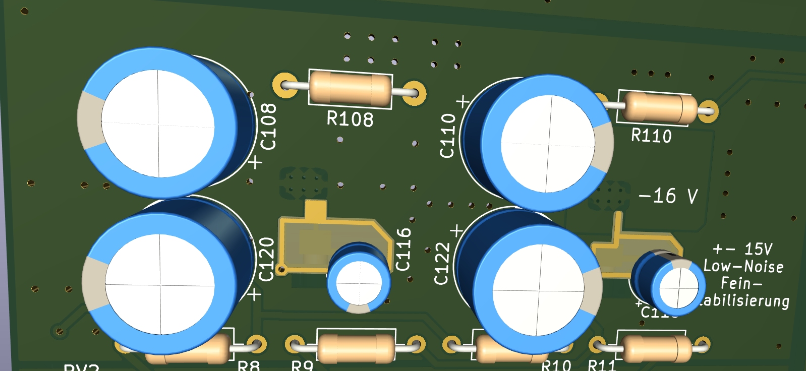
CAD-Ansicht einer Leiterplatte mit Elektrolytkondensatoren und Widerständen
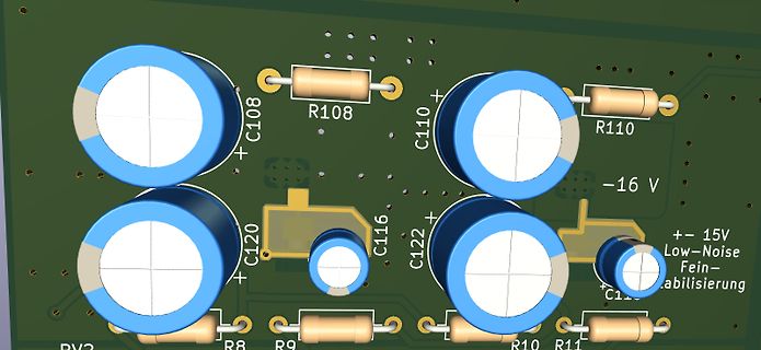
C108 R108 C110 R110 C120 C116 C122 -16 V + - 15V Low-Noise Fein- stabilisierung C111 R8 R9 R10 R11
-
 Bild
Bild
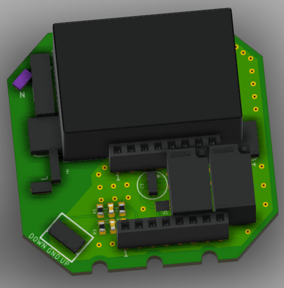
3D-CAD-Modell einer Leiterplatte mit Bauteilen
82 83 84 85 86 87 88 89 90 91 92 93 94 95 96 97 98 99 100 101 102 103 104 105 106 107 108 109 110 111 112 113 114 115 116 117 118 119 120 121 122 123 124 125 126 127 128 129 130 131 132 133 134 135 136 137 138 139 140 141 142 143 144 145 146 147 148 149 150 151 152 153 154 155 156 157 158 159 160 161
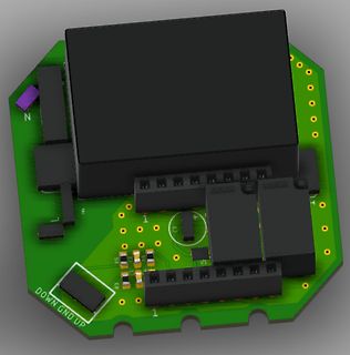
-
 Bild
Bild
CAD-Ansicht eines Leiterplatten-Layouts
, R94, R95, R96, R97, R98, R99, R100, R101, R102, R103, R104, R105, R106, R107, R108, R109, R110, R111, R112, R113, R114, R115, R116, R117, R118, R119, R120, R121, R122, R123, R124, R125, R126, R127, R128, R129, R130, R131, R1
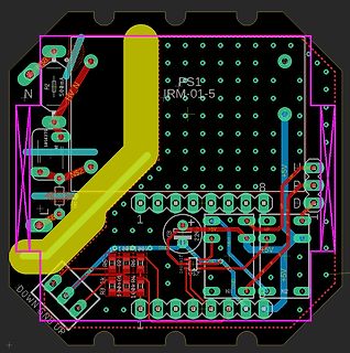
-
Thread
Erfahrungen mit BEV Betrieb in Kanada
Nun ja, wenn die Liste halbwegs stimmt, war das letzte, katastrophale Hochwasser 1910, also satte 111 Jahre zuvor, das sind 4 Generationen! Da kann man schon mal vergessen, wie schlimm es kommen kann! Siehe Japan, der Tsunami 2011 war auch "überraschend" stark. Die Gefahr, vor allem für die küstennahen
ja, wenn die Liste halbwegs stimmt, war das letzte, katastrophale > Hochwasser 1910, also satte 111 Jahre zuvor, das sind 4 Generationen! Da > kann man schon mal vergessen, wie schlimm es kommen kann! Siehe Japan, > der Tsunami 2011 war auch "überraschend" stark. Aus Untersuchungen in Japan
-
Thread
alte Turbo-C-Software unter win95 neu für WIN10.
# append to data_in array print('>>>', data_in) # >>> [13, 10, 77, 80, 89, 58, 32, 115, 111, 102, 116, 32, 114, 101, 98, 111] [/code]
-
 Bild
Bild
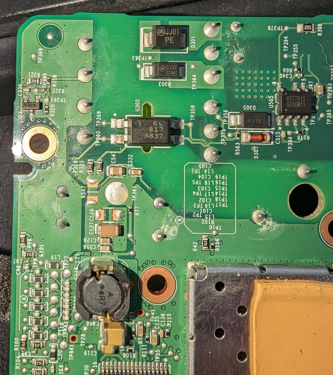
Nahaufnahme einer bestückten Leiterplatte
C54, C332, C31, R33, C31, C127, C128, C59, C96, R101, L19, TP341, R10, R100, R32, C19, R108, TP34, R111, C135, C136, L15, TP10, R102, R42, R45, R56, L14, L104, TP19, TP15, TP18, C103, TP14, L17, TP13, C102, TP17, C105, L14, TP1, TP4, U302, D303, TP364, D301, TP378, TP394, TP355, R69, C40, R78, TP385,
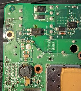
-
 Bild
Bild
Schaltplan eines Netzteils
C89 C90 C91 C92 C93 C94 C95 C96 C97 C98 C99 C100 C101 C102 C103 C104 C105 C106 C107 C108 C109 C110 C111 C112 C113 C114 C115 C116 C117 C118 C119 C120 C121 C122 C123 C124 C125 C126 C127 C128 C129 C130 C131 C132 C133 C134 C135 C136 C137 C138 C139 C140 C141 C142 C143 C1
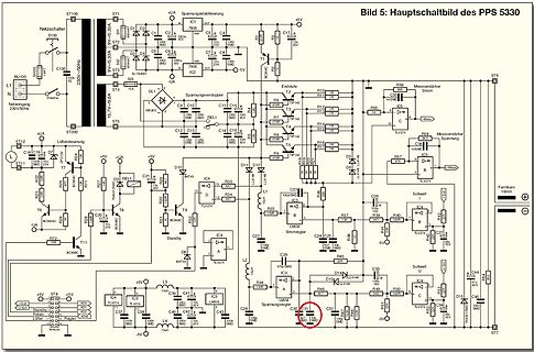
-
 Bild
Bild
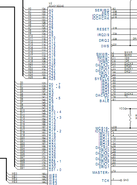
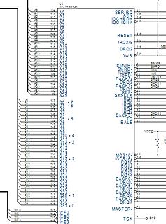
Ausschnitt eines Schaltplans mit Pinbelegungen
XC4013Q240 A0 133 A1 132 A2 131 A3 130 A4 128 A5 127 A6 125 A7 124 A8 115 A9 114 A10 113 A11 112 A12 111 A13 110 A14 109 A15 108 A16 107 A17 106 A18 105 A19 104 A20 103 A21 102 A22 101 A23 100 A24 99 A25 D0 129 D1 128 D2 127 D3 126 D4 125 D5 124 D6 123 D7 122 D8 121 D9 120 D10 119 D11 118 D12 117 D13 116 D14 115 D15 114 D16 113 D17 112 D18 111 D19 110 D20 109 D21 108 D22 107 D23 106 D24 105 D25 104 D26 103 D27 102 D28 101 D29 100 D30 99 D31 0 WE0 184 WE1 183 WE2 182 WE3 181 SERIRQ 82 IOCHRDY 235 IOCHK 216 RESET 218 IRQ2/9 228 DRQ2 OWS 231
-
 Bild
Bild
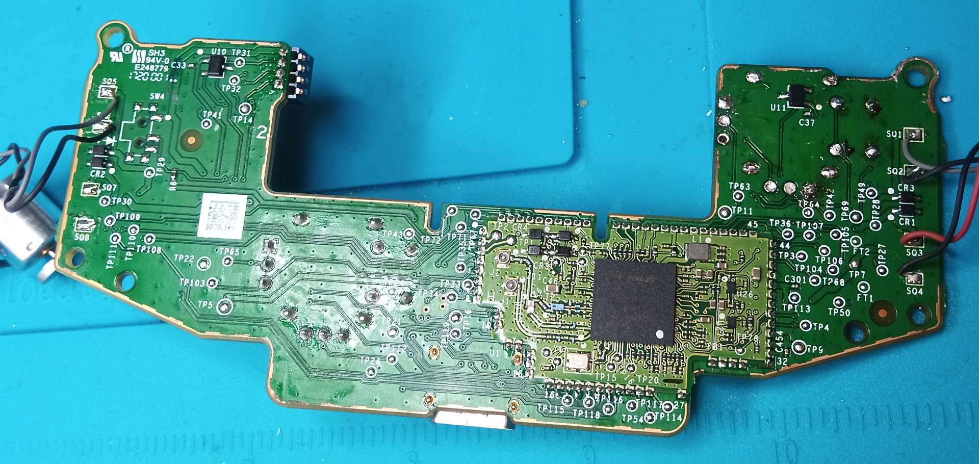
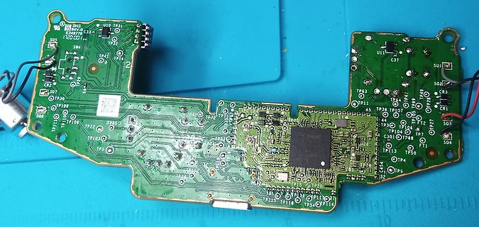
Grüne Leiterplatte mit elektronischen Bauteilen
SH3 U10 TP31 E24879 C33 TP32 SW4 TP41 TP14 SO5 CR2 SO7 TP30 TP109 TP111 TP108 TP106 TP22 TP5 TP103 TP43 TP24 TP115 TP118 TP54 TP114 TP4 TP113 TP7 TP68 TP27 TP46 TP42 TP11 TP36 TP3 TP104 C301 TP50 TP28 CR3 SO2 CR1 SO3 FT1 U11 C37 TP9
-
 Bild
Bild
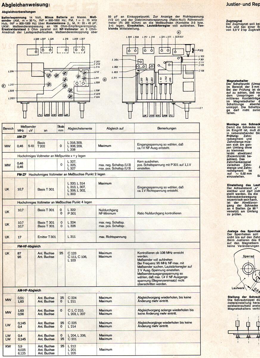
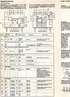
Schaltplan und Messprotokoll eines Netzteils
Schaltplan, L20, L26, L309, L307, L316, L308, L302, L314, L317, L303, L304, L301, P301, P302, C201, C111, C129, C103, L216, L214, L205, L206, L201, L208, L205, C225, C224, L211, L210, L207, L212, L201, L206, L214, L215
-
 Bild
Bild
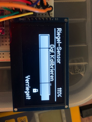
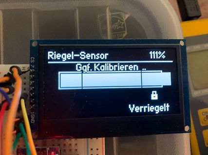
LCD-Display mit Statusanzeige eines Riegel-Sensors
Riegel-Sensor 111% Ggf. Kalibrieren .. Verriegelt
-
 Bild
Bild
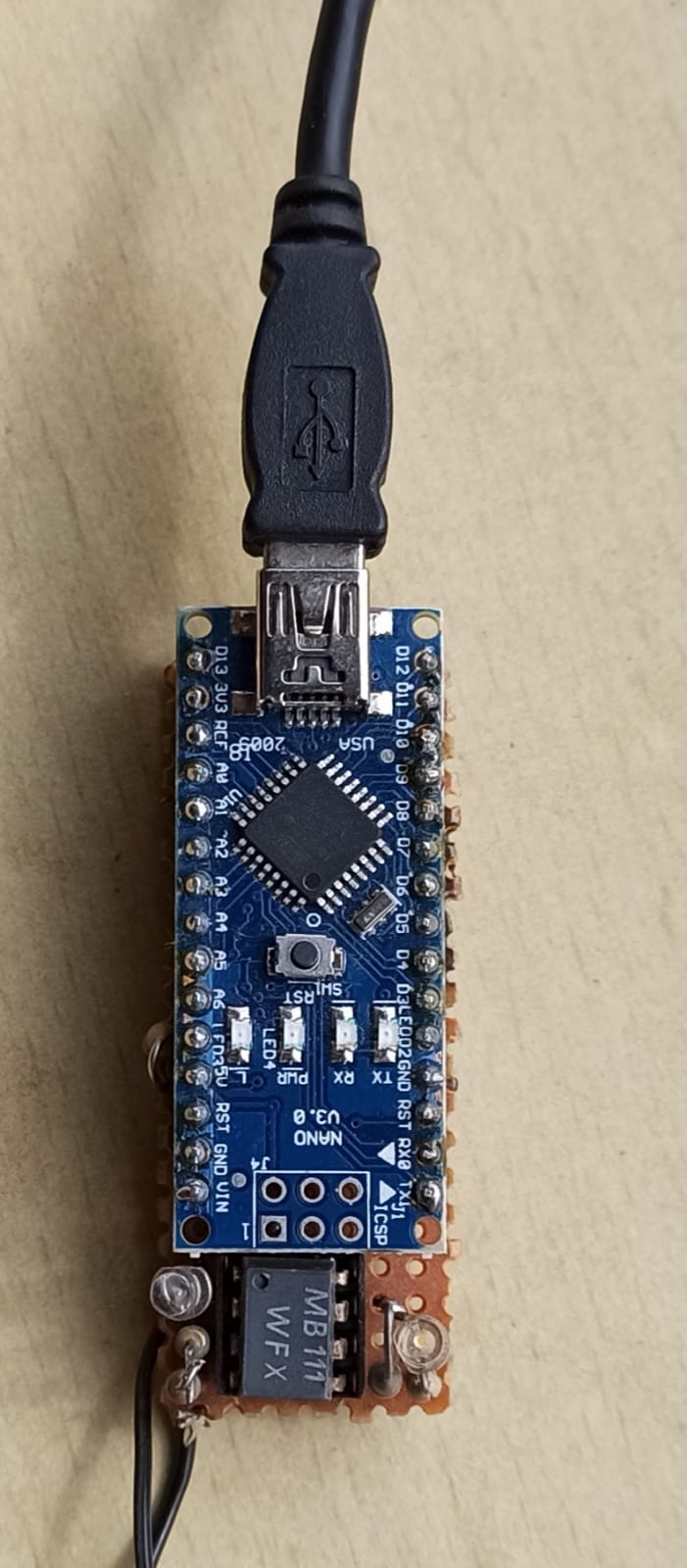
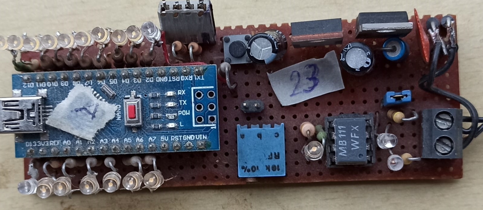
Arduino Nano Mikrocontroller auf Lochrasterplatine
A0 A1 A2 A3 A4 A5 D0 D1 D2 D3 5V GND VIN RST RX 0 TX 1 CSP LED1 LED2 GND RST RX 0 TX 1 NANO V3.0 MB 111 WFX
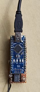
-
 Bild
Bild
Selbstbau-Elektronik mit Arduino Nano auf Lochrasterplatine
Arduino Nano, RX, TX, GND, 5V, RST, VIN, 10K 10%, MB 111 WFX, 23
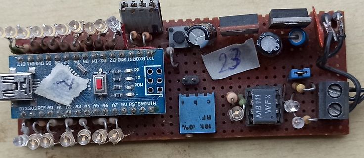
-
 Bild
Bild
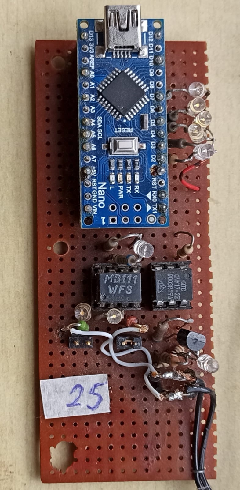
Aufbau mit Arduino Nano auf Lochrasterplatine
D7, D6, D5, D4, D3, D2, D1, D0, RX, TX, RST, GND, VIN, A0, A1, A2, A3, A4, A5, SCL, SDA, RESET, MB111, WFS, QTC, CHY17-22, 900SR191, 25
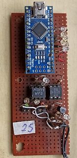
-
 Bild
Bild
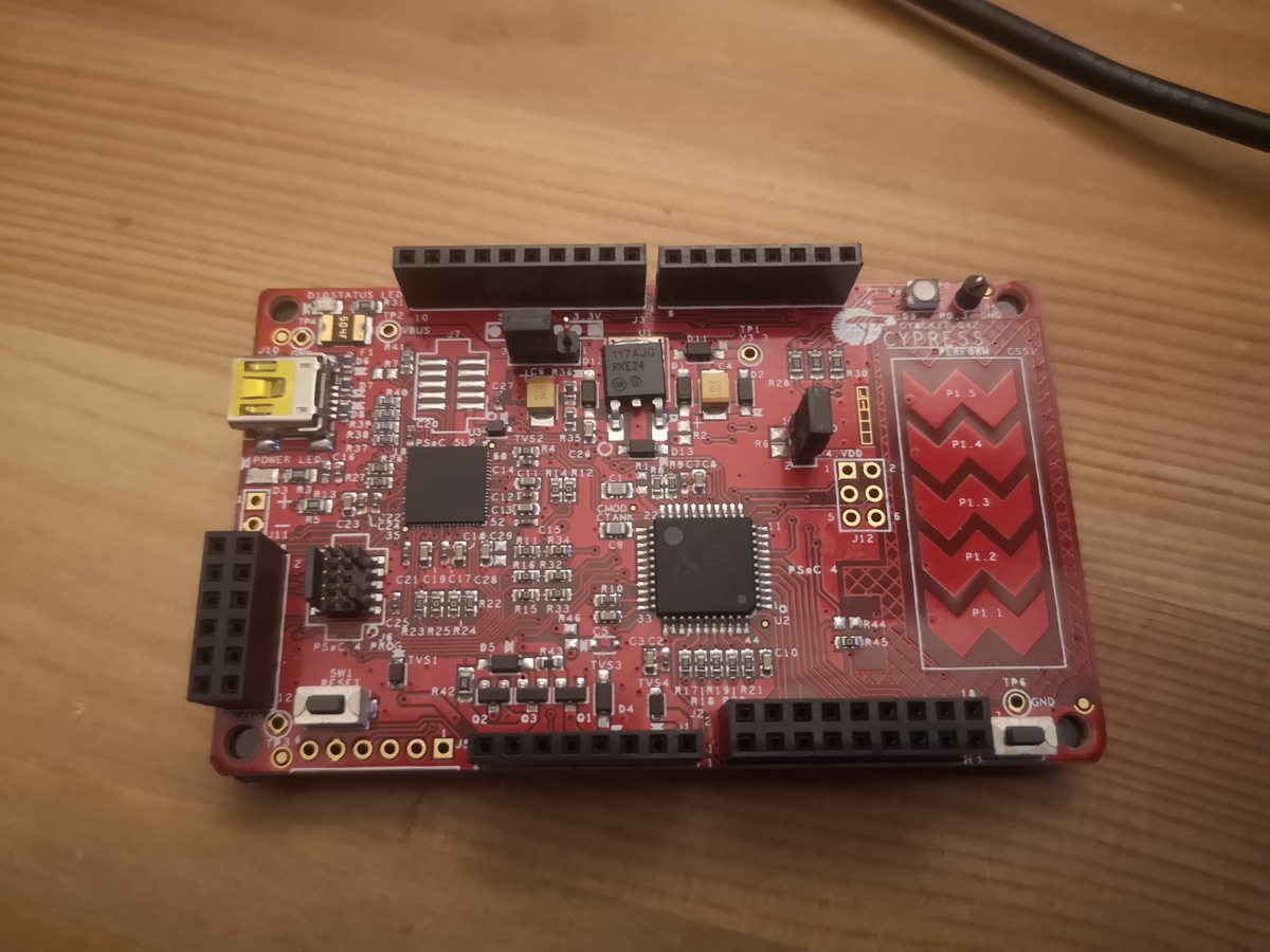
Rote Mikrocontroller-Leiterplatte auf Holztisch
, J94, J95, J96, J97, J98, J99, J100, J101, J102, J103, J104, J105, J106, J107, J108, J109, J110, J111, J112, J113, J114, J115, J116, J117, J118, J119, J120, J121, J122, J123, J124, J125, J126, J127, J128, J129, J130, J131, J132, J1
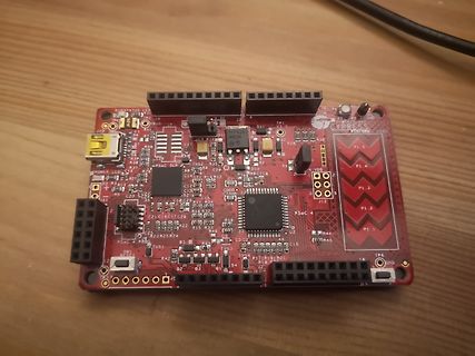
-
 Bild
Bild
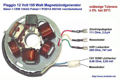
Piaggio 12 Volt 105 Watt Magnetzündgenerator Stator
CEM 135/A2 Polrad = PCE/1A 992746 >rechtsdrehend zulässige Toleranz ± 5% bei 20°C Zündimpulsgeber 111 Ohm, 2,5 µH Massekabel HSP-Ladeanker 520 Ohm, 747 mH 12V 105W Lichtanker 0,46 Ohm, 2,53 mH Massekabel http://www.motelek.net
-
 Bild
Bild
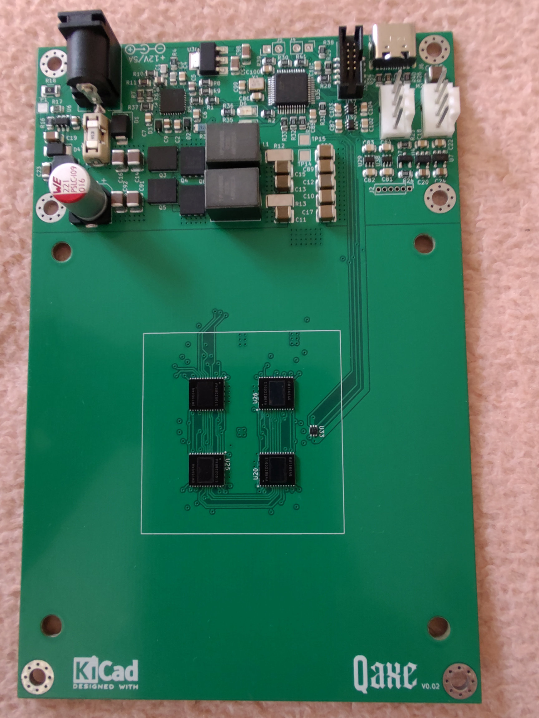
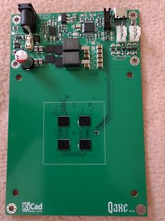
Bestückte und unbestückte grüne Leiterplatte
, R94, R95, R96, R97, R98, R99, R100, R101, R102, R103, R104, R105, R106, R107, R108, R109, R110, R111, R112, R113, R114, R115, R116, R117, R118, R119, R120, R121, R122, R123, R124, R125, R126, R127, R128, R129, R130, R131, R132, R133, R134, R135, R136, R137, R138, R139, R140, R141, R142, R143, R144,
-
 Bild
Bild
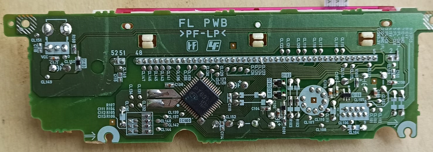
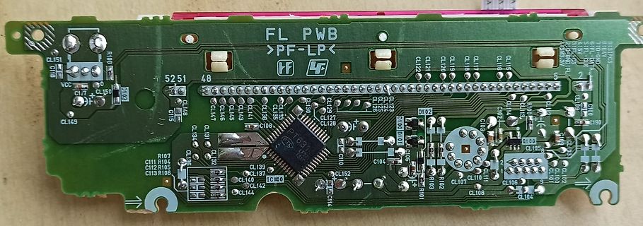
Grüne Leiterplatte mit elektronischen Bauteilen
CL127 CL126 CL125 CL124 CL123 CL122 CL121 CL120 CL119 CL118 CL117 CL116 CL115 CL114 CL113 CL112 CL111 CL110 CL109 CL108 CL107 CL106 CL105 CL104 CL103 CL102 CL101 CL100 CL99 CL98 CL97 CL96 CL95 CL94 CL93 CL92 CL91 CL90 CL89 CL88 CL87 CL86 CL85 CL84 CL83 CL82 CL81 CL80 CL79 CL78 CL77 CL76 CL75 CL74 CL73
-
Thread
ADS1115 und TXS0108 auf PCB an Raspberry
müssen die nicht irgendwo angeschlossen werden? Der Ausgang kann ja offen bleiben, aber ADDR: The ADS111x have one address pin, ADDR, that configures the I2C address of the device. This pin can be connected to GND, VDD, SDA, or SCL, allowing for four different addresses to be selected von open ist nicht
-
 Bild
Bild
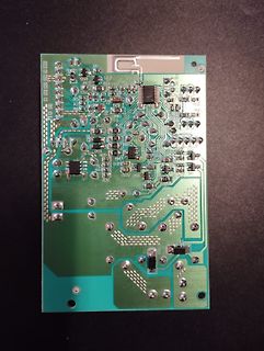
Foto einer geätzten Leiterplatte
, R94, R95, R96, R97, R98, R99, R100, R101, R102, R103, R104, R105, R106, R107, R108, R109, R110, R111, R112, R113, R114, R115, R116, R117, R118, R119, R120, R121, R122, R123, R124, R125, R126, R127, R128, R129, R130, R131, R132, R133, R134, R135
-
 Bild
Bild
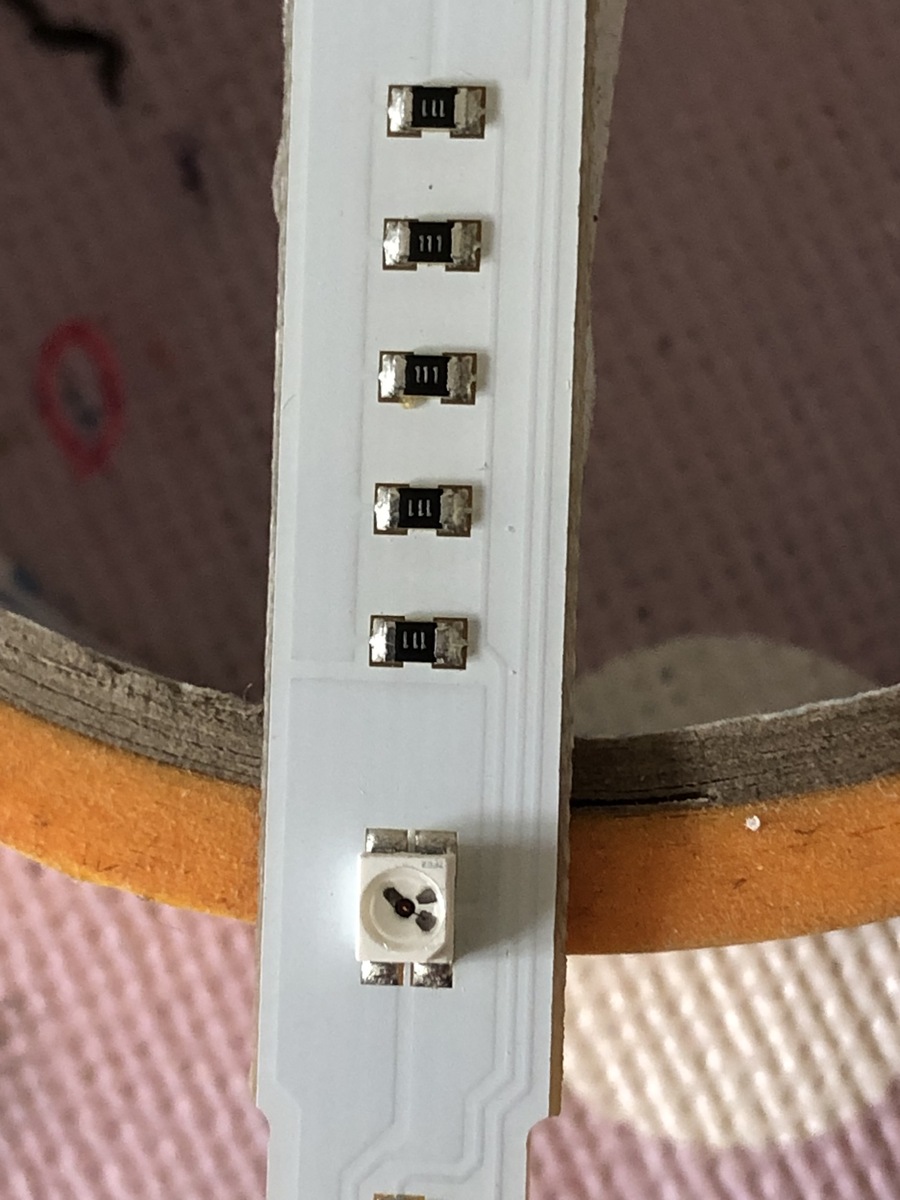
Foto einer Leiterplatte mit SMD-Bauteilen
, R94, R95, R96, R97, R98, R99, R100, R101, R102, R103, R104, R105, R106, R107, R108, R109, R110, R111, R112, R113, R114, R115, R116, R117, R118, R119, R120, R121, R122, R123, R124, R125, R126, R127, R128, R129, R130, R131, R132, R133, R134, R135, R136, R137, R138, R139, R140, R141, R142, R143, R144,