-
PDF
AiMS2000.pdf
CAN_STBY/4.4C P1.31/SCK1/AD0.5 P0.23/AD0.0/I2SRX_CLK/CAP3.0 P0.23/5.3B O , R 28 VDD3.3V P2.0/5.3B 75 P2.0/PWM1.1/TXD1/TRACECLK P0.24/AD0.1/I2SRX_WS/CAP3.1 8 P0.24/5.3B - 3 P2.1/5.3B 74 P2.1/PWM1.2/RXD1 P0.25/AD0.2/I2SRX_SDA/TXD3 7 TX3/5.1A 100nF K 8 P2.2/5.3B 73 P2.2/PWM1.3/CTS1/TRACEDATA3 P0.26/AD0.3/AOUT/RXD3 6 RX3/5.1A C30 1 A M 3 P2.3/5.4B 70 P2.3/PWM1.4/DCD1/TRACEDATA2 P0.27/SDA0/USB_SDA 25 SDA0/4.6A Z L 3 BUTT1 69 P2.4/PWM1.5/DSR1/TRACEDATA1 P0.28/SCL0/USB_SCL 24 SCL0/4.6A 4 + 68 P2.5/PWM1.6/DTR1/TRACEDATA0 P0.29/USB_D+ 29 3 13 NC 67 P2.6/PCAP1.0
in „Schaltplan Prüfung/Kritik LPC1769 + IMU + Bluetooth“ · Mikrocontroller und Digitale Elektronik ·
-
Datei
bas_main.bas
Prallschalter Rechts Pind.2 = Eingang Radencoder Int0 Pind.3 = Eingang Radencoder Int1 Pind.4 = Motor2 Pwm Timer1 Pwrmb Pind.5 = Motor1 Pwm Timer1 Pwrma Pind.7 = Testpin 10ms Int Timer 0 = Sony Fernsteuerung Cntrl - S - Code Bzw. Sircs - Code Sony Hat Keinen Rc5 - Code !!! Timer 1 = Pwm Fuer 2 Motoren Timer
-
Datei
bas_main.bas
Prallschalter Rechts Pind.2 = Eingang Radencoder Int0 Pind.3 = Eingang Radencoder Int1 Pind.4 = Motor2 Pwm Timer1 Pwrmb Pind.5 = Motor1 Pwm Timer1 Pwrma Pind.7 = Testpin 10ms Int Timer 0 = Sony Fernsteuerung Cntrl - S - Code Bzw. Sircs - Code Sony Hat Keinen Rc5 - Code !!! Timer 1 = Pwm Fuer 2 Motoren Timer
in „Mega16 für Roboter die richtige Wahl ?“ · Mikrocontroller und Digitale Elektronik ·
-
Datei
bas_main.bas
Prallschalter Rechts Pind.2 = Eingang Radencoder Int0 Pind.3 = Eingang Radencoder Int1 Pind.4 = Motor2 Pwm Timer1 Pwrmb Pind.5 = Motor1 Pwm Timer1 Pwrma Pind.7 = Testpin 10ms Int Timer 0 = Sony Fernsteuerung Cntrl - S - Code Bzw. Sircs - Code Sony Hat Keinen Rc5 - Code !!! Timer 1 = Pwm Fuer 2 Motoren Timer
in „eine lanze für den bascom-avr-compiler brechen...“ · Projekte & Code ·
-
PDF
WS2801.pdf
display • Wide constant output current range 5~150mA • PWM signal generator • Build in PWM dimming scheme for each output channel, • LCD TV back lighting supports free-run, especially suitable for low cost controller application • PWM free-run capability(refresh
in „Sammelbestellung Adafruit - Digital Addressable RGB LED w/ PWM waterproof flexi strip (LPD8806)“ · Markt ·
-
PDF
WS2801.pdf
display • Wide constant output current range 5~150mA • PWM signal generator • Build in PWM dimming scheme for each output channel, • LCD TV back lighting supports free-run, especially suitable for low cost controller application • PWM free-run capability(refresh
in „WS2801 mehrere LEDs mit KSQ anschließen“ · Analoge Elektronik und Schaltungstechnik ·
-
Datei
8pwm_wert_speicherung_im_eeprom.asm
;Demoprogramm für 8-fach-PWM mit Tastensteuerung und Pollin-LCD 4x27. ;8 LEDs gegen Vcc an Port B (STK500) ;4 entprellte Tasten gegen GND für die einzelnen PWM-Kanäle an Port C ;Davon 2 Tasten (Dimm-Tasten) mit Repeat-Funktion
in „MENÜ-STEUERUNG“ · Mikrocontroller und Digitale Elektronik ·
-
Datei
test_m162.txt
;Demoprogramm für 8-fach-PWM mit Tastensteuerung und Pollin-LCD 4x27. ;8 LEDs gegen Vcc an Port B (STK500) ;4 entprellte Tasten gegen GND für die einzelnen PWM-Kanäle an Port C ;Davon 2 Tasten (Dimm-Tasten) mit Repeat-Funktion
in „MENÜ-STEUERUNG“ · Mikrocontroller und Digitale Elektronik ·
-
Datei
test_1_m162.txt
;Demoprogramm für 8-fach-PWM mit Tastensteuerung und Pollin-LCD 4x27. ;8 LEDs gegen Vcc an Port B (STK500) ;4 entprellte Tasten gegen GND für die einzelnen PWM-Kanäle an Port C ;Davon 2 Tasten (Dimm-Tasten) mit Repeat-Funktion
in „MENÜ-STEUERUNG“ · Mikrocontroller und Digitale Elektronik ·
-
Datei
Auszug.c
non inverting PWM1A TCCR1A |= (1<<COM1B1); // non inverting PWM1B TCCR1A |= (1<<WGM10); // Fast PWM, TOP: 0x00FF TCCR1B = (1<<WGM12); // siehe: WGM10 TCCR1B |= (1<<CS10); // Prescaler = 1 TIMSK1 = (1<<TOIE1); // overflow Interrupt enable OCR1A = 128; OCR1B = 128; // Timer2 TCCR2A = (1<<COM2A1); // non inverting PWM2A TCCR2A |= (1<<COM2B1); // non inverting PWM2B TCCR2A |= (1<<WGM20) | (1<< WGM21); // Fast PWM, TOP: 0xFF TCCR2B = (1<<CS20); // Prescaler = 1 OCR2A = 128; OCR2B = 128; // ADC ADMUX = (1<<REFS0) |
in „Timer 0-2 laufen mit falschem prescaler“ · Mikrocontroller und Digitale Elektronik ·
-
Datei
main.c
); void status(void); void main(void) { WDTCTL = WDTPW + WDTHOLD; // Stop WatchDogTimer init_PWM_TimerA(); status(); // Statussignale for(;;) { _BIS_SR(CPUOFF); _NOP(); } } // Initialize PWM Timer //--------------------- void init_PWM_TimerA(void) { TACTL = TASSEL1 + TACLR; // SMCLK, Clear Tar CCTL0 = OUTMOD_4; // OutputMode = Toggle CCR0 = 30000; // PWM Periode ~30ms das Register zählt von 30000 bis CCTL1 = OUTMOD_7; // CCR1 reset/set CCR1 = 1000; // ON oder OFF Zeit für das Signal // CCTL2 = OUTMOD_7; // CCR2 = 29000; P1DIR |= 0x04; // P1.2 PWM output
in „PWM Verständnis über CCR Register“ · Mikrocontroller und Digitale Elektronik ·
-
Datei
Drycell.c
//PWM Lüfter konfigurieren TCCR0 |= (1<<WGM21); // TCCR0 |= (1<<WGM20); // Timer Einstellung Fast PWM, 8-bit TCCR0 |= (1<<CS22); // Vorteiler 256 TCCR0 |= (1<<COM21); // Nicht invertierender PWM-Modus OCR0
in „Lüftersteuerung über adc“ · Mikrocontroller und Digitale Elektronik ·
-
PDF
MC.pdf
SLUS353B–NOVEMBER 2003–REVISED APRIL 2007 Block Diagram Quad Sel 22 5V RC-Osc 25 OSC S Q REFERENCE 2 VREF PWM CLOCK PWM In 26 R E/A Out 27 E/A In(+) 1 2.9V E/A In (–)28 10 A SSTART 24 ISENSE 3 R Q Q1 ABS VALUE 0.2V 2.5V 250 ISENSE1 4 2X S ISENSE2 5 3.1V VCC 19 9V PWM OV-Coast 23 CLOCK 1.75V 18 PUA Dir 6 17
in „Ansteuerung BrusslessDC Motor mit MSP430“ · Mikrocontroller und Digitale Elektronik ·
-
Datei
FPWM_Mode7.asm
Programm FPWM_Mode7.ASM ;* ;* Für ATtiny13 im Auslieferungszustand ( High = $FF ; Low = $6A ) ;* ;* ;* Am PWM-Pinn 6 ( OC0B ) wird eine PWM im Mode 7 ausgegeben, ;* die mittels zweier Potentiometer eingestellt wird. ;* Wobei ein Poti Pinn 2 ( ADC3 ) bedient und damit den Tastgrad der PWM ;* bestimmt.Das andere
in „ATtiny13 Fast PWM-Mode mit OCR0A und extremwerten“ · Mikrocontroller und Digitale Elektronik ·
-
PDF
CPSignal_Wallbox_mit__C.pdf
nachgedacht Ich würde das nicht mit zwei GPIOs und Transistoren improvisieren, sondern den µC nur das 1-kHz-PWM erzeugen lassen und damit einen analogen Umschalter zwischen +12 V und −12 V ansteuern. Empfohlene Schaltung +12 V │ ┌─────┴─────┐ µC PWM, 1 kHz ──────►│ SEL │ │ TMUX6219 ├───── 1 kΩ / 1 % ───── CP
in „saubere Rechtecksignalpegelwandlung 0/5V auf +12/-12V“ · Mikrocontroller und Digitale Elektronik ·
-
Datei
Maiskolben_TFT.ino
//PWM Prescaler = 64 490Hz //TCCR2B = (TCCR2B & 0b11111000) | 4 //PWM Prescaler = 32 980Hz //TCCR2B = (TCCR2B & 0b11111000) | 3; //PWM Prescaler = 8 3.9kHz //TCCR2B = (TCCR2B & 0b11111000) | 2 //PWM Prescaler
in „Maiskolben Lötstation Display steht Kopf“ · Mikrocontroller und Digitale Elektronik ·
-
Datei
Maiskolben_TFT.ino
//PWM Prescaler = 64 490Hz //TCCR2B = (TCCR2B & 0b11111000) | 4 //PWM Prescaler = 32 980Hz //TCCR2B = (TCCR2B & 0b11111000) | 3; //PWM Prescaler = 8 3.9kHz //TCCR2B = (TCCR2B & 0b11111000) | 2 //PWM Prescaler
in „Probleme bei kompilieren des Maiskolben-Sketch's“ · Mikrocontroller und Digitale Elektronik ·
-
PDF
R8C22-23_Group_Hardware_Manual.pdf
shows the Block Diagram of PWM Mode, Table 14.27 lists the PWM Mode Specifications. Figures 14.64 to 14.73 show the Registers Associated with PWM Mode and Figures 14.74 to 14.75 show the Operations of PWM Mode. TRDi Compare match
in „Fragen zu Renesas µC (R5F2122CKFP)“ · Mikrocontroller und Digitale Elektronik ·
-
Datei
main1.c
on PWM(true); delay_10us(80); redOFF; PWM(false); delay_10us(3000); _EINT(); // General Interrupt Enable gravCLEAR; // P2.3 IFG clear gravON; // P2.3 int enabled } else{ PWM(false); _EINT(); // General Interrupt
in „MSP430 Generelle PWM Frage“ · Mikrocontroller und Digitale Elektronik ·
-
PDF
230V_PWM_DIMMER.pdf
+5V R4 V1 R9 MISO MISO +5V 270R MOC3042 1k SCK SCK MOSI MOSI PWM1 1 6 RESET ReseGND +5V T1 2 4 X1-1 BTA16-800 R1 E U$1 GND X1-2 10k R GND 1 PA2(/RESET) (UCSK)PB7 19 SCK V2 18 MISO R5 MOC3042 R6 (MISO)PB6 17 MOSI PWM2 270R 1 6 1k (MOSI)PB5 16 (OC1B)PB4 15 PWM1 (OC1A)PB3 PWM2 T2 X2-1 (OC0A)PB2 14 PWM3 2 4 BTA16-800 (AIN1)PB1 13 TASTER_HELLER X2-2 (AIN0)PB0 12 TASTER_DUNKLER GND 4 PA1(XTAL2) L V3 5 X7-1 R7 MOC3042 R8 +5V PA0(XTAL1) 11 ~ 270R 1 6 1k (ICP)PD6 9 BETRIEB PWM3
in „PWM_DIMMER_230VAC“ · Mikrocontroller und Digitale Elektronik ·
-
Datei
wrtilty.c
OCR OCR0A #define DDROC DDRB #define TIMER0_TOP 255 /* 8-bit PWM */ //Set COM0A1:0 = 2 for non-inverted pwm and 3 for inverted pwm //Use the following line for FastPWM //# define TIMER0_PWM_INIT _BV(WGM00) | _BV(WGM01) | _BV(COM0A1) //Use the following line for PhaseCorrectPWM
in „Stromstärke steuern“ · Analoge Elektronik und Schaltungstechnik ·
-
 Bild
Bild
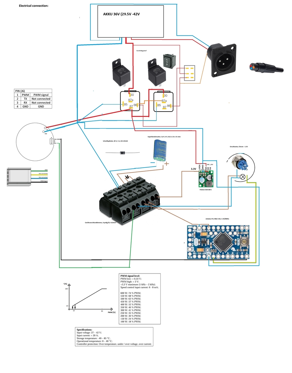
Blockschaltbild einer elektrischen Verbindung mit Akku und Motorsteuerung
Electrical connection: AKKU 36V (29.5V-42V), PIN (RJ) 1 PWM, 2 TX Not connected, 3 RX Not connected, 4 GND GND, 80 97a, 86 97a, Superkondensator, 3.3V, Arduino Pro Mini 3.3V, PWM low < 0.35 V, PWM high > 3.3 V, 2 kHz, 600 W: 74% PWM, 500 W: 85% PWM, 400 W: 102% PWM, 300 W: 131% PWM, 200 W: 176% PWM, 100 W: 234% PWM, Specifications: Input voltage = 27 - 42 V, Input current = 20 A, Storage temperature = -40 - 85 °C, Operational temperature = 0 - 40 °C, Controller
in „Diode hat immernoch Messwerte“ · Analoge Elektronik und Schaltungstechnik · · Diagramme
-
PDF
PWM-Controller_ICE2QS01.pdf
as the time phase I in Figure 3, the 3.3 Normal Operation VCC voltage increase near linearly. The PWM section of the IC can be divided into two VCC main portions: PWM controller for normal operation and PWM controller for burst mode operation. The VVCCon i ii iii PWM controller for normal operation
in „Ausfall Netzteil HAMEG HMO3524“ · Analoge Elektronik und Schaltungstechnik ·
-
Datei
ver1.0_26.07.02.bas
ld r22,x+ 'alten Wert holen ld r23,x+ 'alten Wert holen ld r24,x+ 'alten Wert holen ld r16,x+ 'hole pwm_takt '12 cpi r16,255 'pwm_takt=255? brne asm_noclear ' nee, überspringe clr r21 'lösche Byte=0 clr r22 'lösche Byte=0 clr r23 'lösche Byte=0 clr r24 'lösche Byte=0 Asm_noclear: '3 tst r16 'pwm_takt=
in „Menüstruktur unter Bascom“ · Mikrocontroller und Digitale Elektronik ·
-
PDF
Chip_222_-_alternative_555.pdf
purpose of which is to generate pulse width capacitor(Cx)isconnected;pin3isthecommonwire modulated (PWM) signal with independent adjustment of frequency. (GND); pin 4 is the output of the PWM signal (OUT Note that the solution of such a problem using the PWM); pin 5 is the control of the output signal
in „Chip 222 - alternative 555“ · Analoge Elektronik und Schaltungstechnik ·
-
PDF
MC32XSG.pdf
data # D15 D14 D13 D12 D11 D10 D9 D8 D7 D6 D5 D4 D3 D2 D1 D0 CHx 2-7 channel address WD PH1x PH0x Onx PWM7x PWM6x PWM5x PWM4x PWM3x PWM2x PWM1x PWM0x control Where: MC32XSG All information provided in this document is subject to © NXP B.V. 2021. All rights reserved. Product data sheet Rev. 5 — 21 July 2021
in „SPI High side switch mit Output Voltage Monitoring?“ · Mikrocontroller und Digitale Elektronik ·
-
Datei
main.c
LED3 (rot) 3: LED4 (blau) Mode-Umschaltung per Taster */ #define NO_OF_LEDS 4 // anz. LEDs #define PWM_STEPS 32 // anz. PWM Abstufungen typedef union { volatile uint8_t l[NO_OF_LEDS]; volatile uint32_t ll; } LED_CMD; /* LED Ports */ typedef struct { volatile uint8_t* port; uint8_t bit; } LED; static
in „Ikea Spöka Hack“ · Mikrocontroller und Digitale Elektronik ·
-
PDF
final_board.pdf
/SCK0 B R u 11 VREFN CS/4.1C 36 P1.21/MCABORT/PWM1.3/SSEL0 BUTT1 B V GND L 1 VSSA 37 P1.22/MC0B/USB_PWRD/MAT1.0 62 NRESET MISO/4.1C P1.23/MCFB1/PWM1.4/MISO0 P0.15/TXD1/SCK0/SCK TX1/4.1A GND 42 38 63 3 4 3 4 84 VDDREG3.3V MOSI/4.1C 39 P1.24/MCFB2/PWM1.5
in „Schaltplan Prüfung/Kritik LPC1769 + IMU + Bluetooth“ · Mikrocontroller und Digitale Elektronik ·
-
PDF
avrtut.pdf
allerdings bei anderen AVR‐Controllern vergleichbar, die Pinbelegung allerdings nicht unbedingt. Um den PWM‐Modus zu aktivieren müssen im Timer/Counter1 Control Register A TCCR1A die Pulsweiten‐ Modulatorbits PWM10 bzw. PWM11 entsprechend nachfolgender Tabelle gesetzt werden: PWM11 PWM10 Bedeutung 0 0 PWM-Modus
-
PDF
sla7024m.pdf
to external open-collector inverter connedAeand dB. SLA7024M, SLA7026M, AND SMA7029M HIGH-CURRENT PWM, UNIPOLAR STEPPER MOTOR CONTROLLER/DRIVERS APPLICATIONS INFORMATION REGULATING THE PWM OUTPUT CURRENT The output current (and motor coil current) waveform is illustrated in Figure 1. Setting the PWM
-
Datei
Car1.ino
const int pwmPin = PB1; // Der Pin, der per PWM gesteuert wird const int duration = 3000; // Dauer für das Hoch- und Runterfahren in Millisekunden const int steps = 255; // Anzahl der Schritte für die PWM (0-255 für 8-Bit PWM) void setup() { pinMode(pwmPin, OUTPUT); // Setzt den Pin als Ausgang } void loop() { // Hochfahren des Pins for (int value = 0; value <= steps; value++) { analogWrite(pwmPin, value); // PWM-Wert auf
in „(AVR) Attiny85 PWM“ · Mikrocontroller und Digitale Elektronik ·
-
PDF
doc4298.pdf
features have been added: Prescalers The Prescalers in ATtiny2313 can be reset. Variable top value in PWM mode. For Timer/Counter1, Phase and Frequency Correct PWM mode in addition to the Phase Correct PWM mode. Fast PWM mode. Timer0 extended with PWM and Output Compare function. Differences Between Most
in „tiny2313-90S2313“ · Mikrocontroller und Digitale Elektronik ·
-
Datei
cgonel.txt
* Initialisierung ******* { wdt_disable(); //Watchdog ausschalten //Ausgänge definieren DDRA |= 1<<PWM | 1<<Richtung | 1<<LED; //PINA6 Ausgang für PWM; PINA7 für Richtung des Motors; //PINA3 als Status: 3x Blink: Initialisierung abgeschlossen // 5x Blink: Lernroutine beginnt // 2x Blink: wähernd Lernroutine
in „Attiny44A interner Takt“ · Mikrocontroller und Digitale Elektronik ·
-
Datei
avr.c
* Initialisierung ******* { wdt_disable(); //Watchdog ausschalten //Ausgänge definieren DDRA |= 1<<PWM | 1<<Richtung | 1<<LED; //PINA6 Ausgang für PWM; PINA7 für Richtung des Motors; //PINA3 als Status: 3x Blink: Initialisierung abgeschlossen // 5x Blink: Lernroutine beginnt // 2x Blink: wähernd Lernroutine
in „Attiny44A interner Takt“ · Mikrocontroller und Digitale Elektronik ·
-
Datei
sketch_dec23a.ino
Pin_A7(PWM_MODE, &GPIOA_BASE->CRL, 7, &TIMER3_BASE->CCR2); ActuatorPin Pin_B0(PWM_MODE, &GPIOB_BASE->CRL, 0, &TIMER3_BASE->CCR3); ActuatorPin Pin_B1(PWM_MODE, &GPIOB_BASE->CRL, 1, &TIMER3_BASE->CCR4); ActuatorPin Pin_B6(PWM_MODE, &GPIOB_BASE->CRL, 6, &TIMER4_BASE->CCR1); ActuatorPin Pin_B7(PWM_MODE, &GPIOB_BASE->CRL, 7, &TIMER4_BASE->CCR2); ActuatorPin Pin_B8(PWM_MODE, &GPIOB_BASE->CRH, 8, &TIMER4_BASE->CCR3); ActuatorPin
in „Blue Pill unter Arduino und RC-Model Servo-Signale“ · Mikrocontroller und Digitale Elektronik ·
-
Datei
Fehlermeldung.cc
1500; //Schleifendurchläufe unsigned char speed=20; unsigned char Dummy=0; unsigned char x; uint8_t pwm_phase=0; uint8_t pwm_soll; unsigned int start; #define gruen PORTA |= (1 << PA0); #define rot PORTA |= (1 << PA1); #define blau PORTD |= (1 << PD2); #define gelb PORTD |= (1 << PD3); #define alle_aus
in „Fehlermeldung Original und gelesene Daten haben unterschiedliche Längen“ · Mikrocontroller und Digitale Elektronik ·
-
PDF
drv8833.pdf
recirculation current flows through the body diodes; in slow decay, the motor winding is shorted. To PWM using fast decay, the PWM signal is applied to one xIN pin while the other is held low; to use slow decay, one xIN pin is held high. Table 3. PWM Control of Motor Speed xIN1 xIN2 FUNCTION PWM 0 Forward PWM, fast decay 1 PWM Forward PWM, slow decay 0 PWM Reverse PWM, fast decay PWM 1 Reverse PWM, slow decay 8 Submit Documentation Feedback Copyright © 2011–2013, Texas Instruments Incorporated Product Folder
in „TI DRV8833 Muss man den PWM Pin wechseln?“ · Mikrocontroller und Digitale Elektronik ·
-
PDF
Rohm_BD6211.pdf
L Forward (OUT1 > OUT2) c L H VCC L H Reverse (OUT1 < OUT2) d H H X L L Brake (stop) __________ e PWM L VCC H PWM Forward (PWM control mode A) __________ f L PWM VCC PWM H Reverse (PWM control mode A) __________ g H PWM VCC PWM L Forward (PWM control mode B) __________ h PWM H VCC L PWM Reverse (PWM
in „Frage zu Entladung von Elko“ · Analoge Elektronik und Schaltungstechnik ·
-
Datei
PWMs_ADC_I2C.asm
Verwendung unbenannter ; Register hier ebenfalls eintragen .def temp = r16 .def PWMCount = r17 .def PWM_1 = r18 ; Helligkeitswert Led1: 0 .. 127 .def PWM_2 = r19 ; Helligkeitswert Led2: 0 .. 127 .def PWM_3 = r20 ; Helligkeitswert Led3: 0 .. 127 .def PWM_4 = r21 ; Helligkeitswert Led4: 0 .. 127 .def temp1
in „I2C Assembler keine Kommunikation zu GY-521(MPU6050)“ · Mikrocontroller und Digitale Elektronik ·
-
 Bild
Bild
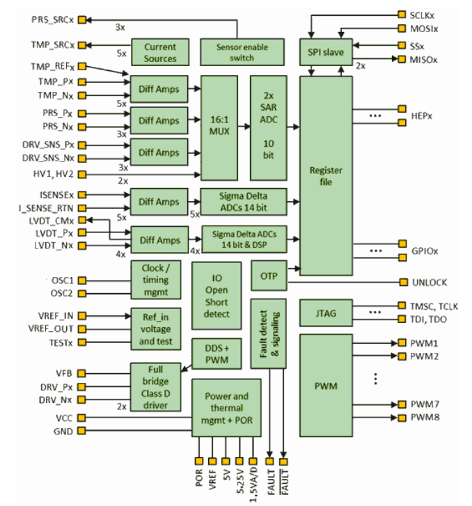
Blockschaltbild eines integrierten Schaltkreises
UNLOCK, VREF_IN, VREF_OUT, TESTx, Sigma Delta ADCs 14 bit & DSP, JTAG, TMSC, TCLK, TDI, TDO, DDS + PWM, Fault detect & signaling, PWM1, PWM2, PWM3, PWM4, PWM5, PWM6, PWM7, PWM8, VFB, DRV_Nx, DRV_Nx, 2x, Full bridge Class D driver, Power and thermal mgmt + POR, VCC, GND, POR, VREF, 5V, 1.5VA/D, 25V, FAULT
in „Low End-Mikrocontroller von Renesas und ST, Funkmodule, Amazon Sidewalk uvam“ · Mikrocontroller und Digitale Elektronik · · Diagramme
-
PDF
sh7020.pdf
4: PWM4 Description 0 Channel 4 operates normally (initial value) 1 Channel 4 operates in PWM mode 228 RENESAS • Bit 3 (PWM Mode 3 (PWM3)): PWM3 selects the PWM mode for channel 3. When the PWM3 bit is set
in „welche GPS-Maus ?“ · Mikrocontroller und Digitale Elektronik ·
-
Datei
main.c
); } static inline void setportdoff(const uint8_t n) { //set PORTD.n low PORTD &= ~(1<<n); } /*### PWM-Routinen zur Motoransteuerung ###*/ void init_timer1(void) //Initialisierung des Timers für Erzeugung des PWM-Signals { /* normale 8-bit PWM aktivieren (nicht invertiert), Das Bit WGM10 wird im Datenblatt auch als PWM10 bezeichnet */ TCCR1A = (1<<COM1A1)|(1<<COM1B1)|(1<<WGM10); /* Einstellen der PWM-Frequenz auf 14 kHz ( Prescaler = 1 ) */ TCCR1B = (1<<CS10); /* Interrupts für Timer1 deaktivieren Achtung : Auch die
in „AT-Mega32/H-Brücke L293DNE/RN-Control1.4“ · Mikrocontroller und Digitale Elektronik ·
-
Datei
pwmtest.asm
2313def.inc" ;------------------------------------------------------------------------------ ;Register für PWM ;------------------------------------------------------------------------------ .def soll1 = r0 ;PWM Kanal 1 .def soll2 = r1 ;PWM Kanal 2 .def soll3 = r2 ;PWM Kanal 3 .def soll4 = r3 ;PWM Kanal 4 .def soll5 = r4 ;PWM Kanal 5 .def soll6 = r5 ;PWM Kanal 6 .def pwmz = r17 .def res = r18 .def con = r19 .def speed = r20 .equ pwm = 100 .equ aus = portb ;-----------------------------------------------------------------
in „Timing Problem“ · Mikrocontroller und Digitale Elektronik ·
-
Datei
baseTimerH.h
enum // ********************************************************************************* Normal = 0, PwmPhaseCorrect8Bit = Regs::WGM_0, PwmPhaseCorrect9Bit = Regs::WGM_1, PwmPhaseCorrect10Bit = Regs::WGM_1|Regs::WGM_0, ClearOnCompareOCR1A = Regs::WGM_2, PwmFast8Bit = Regs::WGM_2| Regs::WGM_0, PwmFast9Bit = Regs::WGM_2|Regs::WGM_1, PwmFast10Bit = Regs::WGM_2|Regs::WGM_1|Regs::WGM_0, PwmPhaseAndFreqCorrectToICR1 = Regs::WGM_3, PwmPhaseAndFreqCorrectToOCR1A = Regs::WGM_3| Regs::WGM_0, PwmPhaseCorrectToICR1 = Regs::WGM_3| Regs::WGM_1
in „Knoten im Kopf, Klassen und Vererbung“ · Mikrocontroller und Digitale Elektronik ·
-
PDF
USBizi_User_Manual.pdf
/E14* 6 P0.26/ADC3/AOUT 31 VSS2 56 P0.22/SD_DAT0 81 P0.4/RD2/E16* /E22* 7 P0.25/ADC2/E24* 32 P1.18/PWM1/E35 57 P0.21/MCIPWR 82 P4.28/TXD3/E13 8 P0.24/ADC1/E26* 33 P1.19/USB_PWR_ 58 P0.20/SD_CMD 83 VSS7 FN/E34 9 P0.23/ADC0/E28* 34 P1.20/PWM2/E25 59 P0.19/SD_CLK 84 VDD(DC-DC-3V)_3 10 VDDA 35 P1.21/PWM3
in „Arm7 (Usbizi) über SPI LCD“ · Mikrocontroller und Digitale Elektronik ·
-
Datei
same70j21.h
PMC ) Number of instances */ #define PMC_INSTS { PMC } /**< \brief (PMC ) Instances List */ #define PWM0 ((Pwm *)0x40020000U) /**< \brief (PWM0 ) Base Address */ #define PWM1 ((Pwm *)0x4005C000U) /**< \brief (PWM1 ) Base Address */ #define PWM_INST_NUM 2 /**< \brief (PWM ) Number of instances */ #define PWM_INSTS { PWM0, PWM1 } /**< \brief (PWM ) Instances List */ #define QSPI ((Qspi *)0x4007C000U) /**< \brief (QSPI ) Base Address */ #define QSPI_INST_NUM 1 /**< \brief (QSPI ) Number of instances */ #define
in „SAM Atmelstudio7 Interupts ohne ASF“ · Mikrocontroller und Digitale Elektronik ·
-
PDF
LT3756.pdf
temp- erature range, otherwise specifications are at T A = 25°C. V IN24V, SHDN/UVLO = 24V, CTRL = 2V, PWM= 5V, unless otherwise noted. PARAMETER CONDITIONS MIN TYP MAX UNITS VINMinimumOperating Voltage VINied to INTVCC 6 V VINShutdown I Q SHDN/UVLO = 0V, PWM= 0V 0.1 1 μA SHDN/UVLO = 1.15V, PWM= 0V 5 μA
-
Datei
Code.txt
} /* PWM */ void PWM (float onReg) { /* Timer 1 Konfigurieren NON Inverting Ausgang OC1B (bei Compare Match Ausgang auf LOW) FAST PWM mit TOP durch ICR1 und Compare durch OC1B f_pwm soll 500 Hz sein: 500 = F_CPU
in „PWM Invertieren“ · Mikrocontroller und Digitale Elektronik ·
-
Datei
Code.c
} /* PWM */ void PWM (float onReg) { /* Timer 1 Konfigurieren NON Inverting Ausgang OC1B (bei Compare Match Ausgang auf LOW) FAST PWM mit TOP durch ICR1 und Compare durch OC1B f_pwm soll 500 Hz sein: 500 = F_CPU
in „PWM Invertieren“ · Mikrocontroller und Digitale Elektronik ·
-
PDF
esp32_datasheet_en.pdf
_f2_in 0 no pwm1_out0a 1’d1 109 pwm0_cap0_in 0 no pwm1_out0b 1’d1 110 pwm0_cap1_in 0 no pwm1_out1a 1’d1 111 pwm0_cap2_in 0 no pwm1_out1b 1’d1 112 pwm1_cap0_in 0 no pwm1_out2a 1’d1 113 pwm1_cap1_in 0 no pwm1_out2b 1’d1 114 pwm1_cap2_in 0 no pwm2_out1h 1’d1 115 pwm2_flta 1 no pwm2_out1l 1’d1 116 pwm2_fltb 1 no pwm2_out2h 1’d1 117 pwm2_cap1_in 0 no pwm2_out2l 1’d1 118 pwm2_cap2_in 0 no pwm2_out3h 1’d1 119 pwm2_cap3_in 0 no
in „LilyGo T-Watch 2020 v1 Micropython“ · Mikrocontroller und Digitale Elektronik ·