-
PDF
BTT_SKR_V1.4-SCH.pdf
71 Uc3.3V C10 J7 2 LED U2 P0.26 6 P0.26/AD0.3/AOUT/RXD3 P P P P P P P 1 5 P P L L _ X D C S D P2.3/PWM1.4/DCD1/TRACEDATA2 70 FAN_PWM 0.1UF 3 74LVC1G125 +5V THB 7 P0.25/AD0.2/I2SRX_SDA/TXD3 P 1 M M R S _ _ _ _ P2.4/PWM1.5/DSR1/TRACEDATA1 69 HE1_PWM 【 E1 】 Neopixel 120R TH0 8 P0.24/AD0.1/I2SRX_WS/CAP3.1
in „Induktiven Sensor (6-36V) an Microcontroller/Mainboard anschließen“ · Mikrocontroller und Digitale Elektronik ·
-
PDF
BTT_SKR_V1.4SCH.pdf
71 Uc3.3V C10 J7 2 LED U2 P0.26 6 P0.26/AD0.3/AOUT/RXD3 P P P P P P P 1 5 P P L L _ X D C S D P2.3/PWM1.4/DCD1/TRACEDATA2 70 FAN_PWM 0.1UF 3 74LVC1G125 +5V THB 7 P0.25/AD0.2/I2SRX_SDA/TXD3 P 1 M M R S _ _ _ _ P2.4/PWM1.5/DSR1/TRACEDATA1 69 HE1_PWM 【 E1 】 Neopixel 120R TH0 8 P0.24/AD0.1/I2SRX_WS/CAP3.1
in „3D-Drucker, Mainboard-Lüfteranschluss erweitern“ · Mikrocontroller und Digitale Elektronik ·
-
PDF
AT91SAM7A3-EK.pdf
USB Device s DDM a DDP NRST T PIT TWI TWD TWCK WDT CAN0 CANRX0 CANTX0 PIOA PIOB CAN1 CANRX1 CANTX1 PWM0 RXD0 PDC PWM1 TXD0 PWM2 SCK0 USART0 PWMC PWM3 RTS0 PWM4 CTS0 PDC PWM5 RXD1 PDC PWM6 TXD1 PWM7 SCK1 USART1 PDC TF0 RTS1 SSC0 TK0 CTS1 PDC I TD0 RXD2 PDC P RD0 TXD2 PDC RK0 SCK2 USART2 RF0 RTS2 PDC TF1
-
Datei
dc_motor_l6203.c
und Rechts- oder Linksdrehung eine proportionale PWM mit entsprechender Drehrichtung vorgeben. Um die Mittenposition gut einstellbar zu halten, werden PWM-Werte <10%-Tastverhaeltnis nicht ausgegeben. Zudem wird der vom ADC eingelesene Potiwert gefiltert
in „Drehzahlregler für DC-Motor, ATmega48-328“ · Projekte & Code ·
-
Datei
PCM-Audio-SD-Card.ino
#define PWM_OUT 11 // OC1A, PB5 #define ERROR_LED 46 #define F_AUDIO 8000 // /Hz #define BUFFER_SIZE 50 #define PWM_PERIOD ((F_CPU/(8L*F_AUDIO))-1) char filename[] = "test_8k.wav"; File myFile; uint32_t filesize
in „Arduino Nano, SD Card, PCM“ · Mikrocontroller und Digitale Elektronik ·
-
Datei
Roboter_mit_Kompass.ino
value); //PWM Speed Control delay(time); } void turn_left (int iL) { digitalWrite(M1,HIGH); digitalWrite(M2,LOW); analogWrite(E1,iL); //PWM Speed Control analogWrite(E2, 255); //PWM Speed Control //delay(780); } void turn_right (int iR) { digitalWrite(M1,LOW); digitalWrite(M2,HIGH); analogWrite(E1, 255); //PWM Speed Control analogWrite(E2, iR); //PWM Speed Control delay(780); } void pause () { digitalWrite(M1,LOW); digitalWrite(M2,LOW); //analogWrite(E1, 0); //PWM Speed Control //analogWrite(E2, 0); //PWM
in „Kompass-Motorsteuerung mit einem Arduino“ · Mikrocontroller und Digitale Elektronik ·
-
Datei
Roboter.c
value); //PWM Speed Control delay(time); } void turn_left (int iL) { digitalWrite(M1,HIGH); digitalWrite(M2,LOW); analogWrite(E1,iL); //PWM Speed Control analogWrite(E2, 255); //PWM Speed Control //delay(780); } void turn_right (int iR) { digitalWrite(M1,LOW); digitalWrite(M2,HIGH); analogWrite(E1, 255); //PWM Speed Control analogWrite(E2, iR); //PWM Speed Control delay(780); } void pause () { digitalWrite(M1,LOW); digitalWrite(M2,LOW); //analogWrite(E1, 0); //PWM Speed Control //analogWrite(E2, 0); //PWM
in „Kompass-Motorsteuerung mit einem Arduino“ · Mikrocontroller und Digitale Elektronik ·
-
Datei
Encoder_PeDa_Original.ino
DDRF #define LEDS PORTF // LEDs against VCC volatile int8_t enc_delta; static uint8_t last; int32_t pwm_wert; void rechteckgenerator_init ( void ); int8_t encode_read( uint8_t klicks ); void encode_init( void ); //////////////////////////////////////////////////////////////////////////////// // void setup
in „Peter Dannegger´s ( PeDa ) Entprellroutine in ein Arduino Sketch einbinden“ · Mikrocontroller und Digitale Elektronik ·
-
Datei
tim.c
CODE BEGIN TIM1_Init 2 */ /* USER CODE END TIM1_Init 2 */ HAL_TIM_MspPostInit(&htim1); } void HAL_TIM_PWM_MspInit(TIM_HandleTypeDef* tim_pwmHandle) { if(tim_pwmHandle->Instance==TIM1) { /* USER CODE BEGIN TIM1_MspInit 0 */ /* USER CODE END TIM1_MspInit 0 */ /* TIM1 clock enable */ __HAL_RCC_TIM1_CLK_ENABLE
in „STM32F407 & CubeMX DMA-PWM“ · Mikrocontroller und Digitale Elektronik ·
-
Datei
sensor_three_phase_BLDC.c
compare match (1<<COM0B1)|(0<<COM0B0)| // Clear OCRB on compare match (1<<WGM01)|(1<<WGM00); // Fast PWM mode TCCR0B = (0<<FOC0A)|(0<<FOC0B)| (0<<WGM02)| // Fast PWM mode (0<<CS02)|(0<<CS01)|(1<<CS00); // Prescaler = CLK/1 //Timer Counter 2. OCRA and OCRB used for motor TCCR2A = (0<<COM2A1)|(0<<COM2A0)
in „AVR 443 Application: __regvar __no_init unsigned char *pDrvPattern @14;“ · Mikrocontroller und Digitale Elektronik ·
-
PDF
AiMS2000.pdf
VREFN BT_INT3/3.3A P G 35 P1.21/MCABORT/PWM1.3/SSEL0 SCL2 B 1 0 11 VSSA G 36 P1.22/MC0B/USB_PWRD/MAT1.0 UART2 +3V3 L 1 0 0 BT_INT2/3.3A 37 P1.23/MCFB1/PWM1.4/MISO0 P0.15/TXD1/SCK0/SCK 62 1 2 P P BT_INT1/3.3A 3 4 42 VDDREG3.3V 38 P1.24/MCFB2/PWM1.5
in „Schaltplan Prüfung/Kritik LPC1769 + IMU + Bluetooth“ · Mikrocontroller und Digitale Elektronik ·
-
PDF
ADC-gesteuerte_PWM_mit_LED-Anzeige.pdf
ADSC)) // Warte, bis Konvertierung abgeschlossen ist ; return ADC; // Gib den ADC-Wert zurück } void PWM_Init() { TCCR0A = (1 << COM0A1) | (1 << WGM01) | (1 << WGM00); // Fast PWM-Modus konfigurieren TCCR0B = (1 << CS01); // Prescaler auf 8 setzen DDRD |= (1 << PD6); // PD6 (Pin 6) als PWM-Ausgang setzen } void SetPWM(uint8_t dutyCycle) { OCR0A = dutyCycle; // PWM Duty Cycle setzen } int main(void) { ADC_Init(); // ADC initialisieren PWM_Init(); // PWM initialisieren DDRH |= (1 << PH6) | (1 << PH5); // PH6 und PH5
-
PDF
MAX1703_1_.pdf
SEL pin setting, voltage MAX1703 R5 0.22 F across the load is regulated using either low-noise ON 10 PWM or low-power operation (Table 2). OUT 0.22 F Low-Noise PWM Operation R3 AIN When CLK/SEL is pulled high, the MAX1703 operates AO in a high-power, low-noise PWM mode. During PWM operation, the MAX1703
in „Verständnisproblem des Max1703 Datenblatt“ · Mikrocontroller und Digitale Elektronik ·
-
PDF
TI_TPS92360_Led_Treiber.pdf
voltage V IN 38 V L Inductor 4.7 10 µH C I Input capacitor 1 µF C O Output capacitor 1 10 µF FPWM PWM dimming signal frequency 5 100 kHz D PWM PWM dimming signal duty cycle 1% 100% T Operating junction temperature –40 125 °C J 6.4 Thermal Information TPS92360 THERMAL METRIC (1) DCK (SC70) UNIT 5 PINS
in „VIN am Konstantstromtreiber?“ · Analoge Elektronik und Schaltungstechnik ·
-
Datei
PPS5330_hack_V1.4.c
10 ~ 15.634ms uint8_t Digi_offset = 96; uint16_t Umax = 30000; // mV Usoll = 5000; // mV uint32_t PWM_value = 15535; // 15540 ~ 30.0V uint16_t OCR_value = 0; PWM_value = (PWM_value * 1000); OCR_value = (((uint32_t)(PWM_value / Umax) * Usoll) / 1000); //set PWM (U-Soll) OCR1A = Digi_offset + OCR_value
in „PPS5330 Labor-Netzteil hack“ · Mikrocontroller und Digitale Elektronik ·
-
PDF
BK2433Datasheetv1.0.pdf
0xA3 0 0_EN PWM1C0 PWM1_PERIOD [7:0] 0xA4 0 PWM1C1 PWM1_DUTY [5:0] PWM1_ 0xA5 0 PERIOD [9:8] PWM1C2 PWM PWM1_PRESCAL[2:0] PWM1_DUTY [9:6] 0xA6 0 1_EN PWMICTL pwm1 pwm0 pwm1 pwm0 / / pwm1 pwm0 0xA7 0 _inte _inte _mod
in „Chinesische USB/nRF24L01 Adpapter“ · Mikrocontroller und Digitale Elektronik ·
-
PDF
SCH_Schematic1_2025-04-25-1.pdf
▯1 ▯2 ▯3 ▯4 ▯5 ▯6 Voltage Regulator ESP8266 ▯A DC1 +12V U2 +3.3V H3 ▯A 1 3 2 GND 3 SW1 4 GND 1 1 PWM2 H2 2 VIN VOUT 4 U1 2.4GHz 2 2 1 3 EP 1 1 2 1 22 GND 2 1 ADJ/GND 2 RST TXD 21 3 2 3 ADC RXD 20 4 3 GND GND +3.3V 4 EN IO5 19 RPM4 +3.3V 4 RPM1 5 IO16 IO4 18 RPM5 PWM1 6 IO14 IO0 17 1 SW2 2 RPM2 7 IO12
in „PWM Lüfter Steuerung mit ESP8266 Tacho Problem“ · Mikrocontroller und Digitale Elektronik ·
-
Datei
kuche.c
------------------------------------------------------- ISR (SIG_OVERFLOW0) { static unsigned char PWM_cnt; #if (INVERT==1) if (PWM_cnt <Red) Ledport &=~(1 << R_PIN); else Ledport |= (1 << R_PIN); if (PWM_cnt <Green) Ledport &=~(1 << G_PIN); else Ledport |= (1 << G_PIN); if (PWM_cnt <Blue) Ledport &=
in „HSV RGB Led Dimmer, C Code & Video & Doku“ · Projekte & Code ·
-
Datei
pins.h
(AIN0) PD6 #define NOK_RST 6 // D7 (AIN1) PD7 #define NOK_CE 7 // D8 (ICP1) PB0 // D9 (OC1A) PB1 (PWM) // D10(SS/OC1B) PB2 (PWM) #define RCsend 10 // D11(MOSI/OC2) PB3 (PWM) #define NOK_BL 11 // D12(MISO) PB4 // D13(SCK) PB5 (LED) // ANALOG // A0 (ADC0) PC0 // A1 (ADC1) PC1 // A2 (ADC2) PC2 // A3 (ADC3
in „ATmega328P mit mehr Pins“ · Mikrocontroller und Digitale Elektronik ·
-
Datei
RC_H_Bridge.c
PWMFlags.Reverse = FALSE; Init_Ports(); Init_Timers(); Init_ISR(); sei(); /* The main loop calculates PWM and detects forward and reverse driving. When pulselength is about 1500, PWM is 0. pulselength < 1470 -> reverse drive and PWM is (pulselength - 1500) DIV 2 for a 2000 µs length we get approx 250 as PWM value pulselength > 1500 forward and PWM is (1500 - pulselength) DIV 2 All this will only be done after a complete measuring cycle */ while (1) { if (ticker > 200) { PWMFlags.Fail = TRUE; PWMFlags.Ready
-
Datei
RC_H_Bridge.c
PWMFlags.Reverse = FALSE; Init_Ports(); Init_Timers(); Init_ISR(); sei(); /* The main loop calculates PWM and detects forward and reverse driving. When pulselength is about 1500, PWM is 0. pulselength < 1470 -> reverse drive and PWM is (pulselength - 1500) DIV 2 for a 2000 µs length we get approx 250 as PWM value pulselength > 1500 forward and PWM is (1500 - pulselength) DIV 2 All this will only be done after a complete measuring cycle */ while (1) { if (ticker > 200 || (good < 50)) { PWMFlags.Fail = TRUE
-
Datei
Blink0.c
char blink0 (void) { char var; static char pwm,x=34,direction; static int faktor=1; faktor=faktor-1; //Im Prinzip eine Warteschleife if(faktor==0) //Bei Ablauf: { if (x==34) //Zählrichtung bestimmen direction=0; else if (x==0) direction=1; if (direction
in „Anfängerfrage: Verhindern eine Funktion zu kopieren in C“ · Mikrocontroller und Digitale Elektronik ·
-
PDF
Tutorial_Teil_3_Prg_Display.pdf
- Teil 3 GFX leds_init(); // Aufruf leds pwm_init(); // Aufruf pwm display_init(); // Aufruf Display gfx_init(); // Aufruf Graphik leds_set_displaylight(1024); // Setzt Displaylicht { // Bringt die darstellbaren Zeichen auf den Schirm gfx_term_goto
in „Tutorial Programmierung Nibo2“ · Mikrocontroller und Digitale Elektronik ·
-
Datei
test.c
io.h> #include <avr/interrupt.h> uint8_t matrix[3][3]; uint8_t spalte = 0; uint8_t zeile = 0; uint8_t pwm_cnt = 0; void main() { } ISR { if (matrix[spalte][0] > pwm_cnt) { // zeile 1 aus } if (matrix[spalte][1] > pwm_cnt) { // zeile 2 aus } if (matrix[spalte][2] > pwm_cnt) { // zeile 3 aus } if (matrix[spalte][3] > pwm_cnt) { // zeile 4 aus } if(pwm_cnt == 255) { pwm_cnt = 0; if(spalte == 3) { spalte = 0; } else { spalte++; } } else { pwm_cnt++; } }
in „LED Matrix PWM, Verständnisfrage“ · Mikrocontroller und Digitale Elektronik ·
-
PDF
TMC5072_datasheet.pdf
wave table should not be less than 244. Best results are obtained with 247 to 252 as peak values. 17 pwm_freq1 PWM frequency %00: f PWM=2/1024 CLK pwm_freq0 selection %01: f =2/683 f 16 PWM CLK %10: f PWM=2/512 CLK %11: f PWM=2/410 CLK 15 PWM_ User defined pwm_ 0: stealthChop disabled GRAD regulation loop
in „TMC5072 SPI Ansteuerung“ · Mikrocontroller und Digitale Elektronik ·
-
Datei
motor1.c
************************************************************ int i=0; //Laufvariable unsigned long pwm_count, pwm_schaltwert, timer0_zaehler=0; //PWM //****************************************************************************** //Interrupt Funktion für Timer0 und Komparator //*********************
in „12V Motorsteuerung mit PIC12f675“ · Mikrocontroller und Digitale Elektronik ·
-
Datei
Main.c
); setup_timer_2(T2_DIV_BY_4, 127, 1); //PWM-Frequenz ist Int_Takt/(4*4*(PWM_FACTOR+1)) //Hauptschleife while (TRUE){ //Schleifenzähler counter++; //Programmtest if (counter==0){ OUTPUT_TOGGLE(PIN_C0); OUTPUT_TOGGLE(PIN_C1); } PWM_VAL = 128; //Zum Testen des PWM-Ausgangs set_pwm1_duty(PWM_VAL); } //Ende der Schleife /while } //Ende des Hauptprogramms /main
in „PIC16F684 und PWM“ · Mikrocontroller und Digitale Elektronik ·
-
Datei
Main.c
_4, 127, 1); //PWM-Frequenz ist Int_Takt/(4*4*(PWM_FACTOR+1)) setup_ccp1(CCP_PWM); //Hauptschleife while (TRUE){ //Schleifenzähler counter++; //Programmtest if (counter==0){ OUTPUT_TOGGLE(PIN_C0); OUTPUT_TOGGLE(PIN_C1); } PWM_VAL = 128; //Zum Testen des PWM-Ausgangs set_pwm1_duty(PWM_VAL); } //Ende der Schleife /while } //Ende des Hauptprogramms /main
in „PIC16F684 und PWM“ · Mikrocontroller und Digitale Elektronik ·
-
Datei
Blink0.c
char blink0 (void) { char var; static char pwm,x=34,direction; static int faktor=1,zufall=200; faktor=faktor-1; //Im Prinzip eine Warteschleife if(faktor==0) //Bei Ablauf: { if (x==34) //Zählrichtung bestimmen direction=0; else if (x==0) direction
in „Anfängerfrage: Verhindern eine Funktion zu kopieren in C“ · Mikrocontroller und Digitale Elektronik ·
-
Datei
880eed3fe10373c0a5d4ca8d0892cc67.txt
not set # CH_C_PWM_GENERAL_SUPPORT is not set # PWM_WAV_SUPPORT is not set # VFS_PWM_WAV_SUPPORT is not set # PWM_MELODY_SUPPORT is not set # ENTCHEN_PWM_MELODY_SUPPORT is not set # TETRIS_PWM_MELODY_SUPPORT is not set # PWM_SERVO_SUPPORT is not set PWM_SERVOS=1 # PWM_SERVO_INVERT is not set # PWM_SERVO_DEFAULT_ENABLED is not set # PWM_FREQ_SUPPORT is not set # PWM_DTMF_SUPPORT is not set # DEBUG_PWM is not set # DEBUG_PWM_SERVO
in „Ethersex will nicht so richtig“ · Mikrocontroller und Digitale Elektronik ·
-
Datei
Arduino_wdt.h
ATmega1281, ATmega2560, ATmega2561, ATmega8HVA, ATmega16HVA, ATmega32HVB, ATmega406, ATmega1284P, AT90PWM1, AT90PWM2, AT90PWM2B, AT90PWM3, AT90PWM3B, AT90PWM216, AT90PWM316, AT90PWM81, AT90PWM161, AT90USB82, AT90USB162, AT90USB646, AT90USB647, AT90USB1286, AT90USB1287, ATtiny48, ATtiny88. Note: This value
in „aktuelle AVR µC - wdt.h - kein RAMPD / CTRL / Enable Bit“ · Mikrocontroller und Digitale Elektronik ·
-
Datei
8pwm2.1.asm.txt
;Demoprogramm für 8-fach-PWM mit Tastensteuerung und Pollin-LCD 4x27. ;8 LEDs gegen Vcc an Port B (STK500) ;4 entprellte Tasten gegen GND für die einzelnen PWM-Kanäle an Port C ;Davon 2 Tasten (Dimm-Tasten) mit Repeat-Funktion
in „MENÜ-STEUERUNG“ · Mikrocontroller und Digitale Elektronik ·
-
PDF
AVR_ATmega_328PB.pdf
PWM, 9- 0x01FF BOTTOM TOP bit 7 0 1 1 1 Fast PWM, 10- 0x03FF BOTTOM TOP bit 8 1 0 0 0 PWM, Phase ICR1 BOTTOM BOTTOM and Frequency Correct 9 1 0 0 1 PWM, Phase OCR4A BOTTOM BOTTOM and Frequency Correct 10 1 0 1 0 PWM, Phase ICR1 TOP BOTTOM Correct 11 1 0 1 1 PWM, Phase OCR4A TOP BOTTOM Correct 12 1 1 0 0 CTC ICR1 Immediate MAX 13 1 1 0 1 Reserved - - - 14 1 1 1 0 Fast PWM ICR1 BOTTOM TOP 15 1 1 1 1 Fast PWM OCR4A
in „ATmega328PB: UART(MC) empfängt falsche Daten“ · Mikrocontroller und Digitale Elektronik ·
-
Datei
lamps_01.asm
PORTB,0 nop nop return pwm_out00 bsf PORTB,0 decf duty0h,1 return pwm_out1 movf duty1h,1 btfss zero goto pwm_out11 bcf PORTB,3 bcf PORTB,5 nop nop return pwm_out11 bsf PORTB,3 bsf PORTB,5 decf duty1h,1 return pwm_out2 movf duty2h,1 btfss zero goto pwm_out22 bcf PORTB,4 nop nop return pwm_out22 bsf PORTB,4 decf duty2h,1 return end
in „Pic Lernen aber wie??“ · Mikrocontroller und Digitale Elektronik ·
-
Datei
stm32f10x_it.c
_3, TIM_CCxN_Disable); /* Channel1 configuration */ TIM_SelectOCxM(TIM1, TIM_Channel_1, TIM_OCMode_PWM1); TIM_CCxCmd(TIM1, TIM_Channel_1, TIM_CCx_Enable); TIM_CCxNCmd(TIM1, TIM_Channel_1, TIM_CCxN_Disable); /* Channel2 configuration */ TIM_SelectOCxM(TIM1, TIM_Channel_2, TIM_OCMode_PWM1 ); TIM_CCxCmd
in „STM32F1 Brushless Motor Steuerung“ · Mikrocontroller und Digitale Elektronik ·
-
Datei
stm32f10x_it.c
_3, TIM_CCxN_Disable); /* Channel1 configuration */ TIM_SelectOCxM(TIM1, TIM_Channel_1, TIM_OCMode_PWM1); TIM_CCxCmd(TIM1, TIM_Channel_1, TIM_CCx_Enable); TIM_CCxNCmd(TIM1, TIM_Channel_1, TIM_CCxN_Disable); /* Channel2 configuration */ TIM_SelectOCxM(TIM1, TIM_Channel_2, TIM_OCMode_PWM1 ); TIM_CCxCmd
in „STM32F1 Brushless Motor Steuerung“ · Mikrocontroller und Digitale Elektronik ·
-
Datei
TimerOne.cpp
register for pwm output pin TCCR1A |= _BV(COM1A1); // activates the output pin } else if(pin == 2 || pin == 10) { DDRB |= _BV(PORTB2); TCCR1A |= _BV(COM1B1); } setPwmDuty(pin, duty); resume(); // Lex - make sure the
in „Rotary Encoder macht immer 4 Schritte“ · Mikrocontroller und Digitale Elektronik ·
-
PDF
4412FGPR-203.pdf
Wire size (AWG) 24 Insulation diameter 1,35 mm Wire Color Operation 1 red + UB 2 blue - GND 3 violet PWM 11/09/2017 page 3 of 15 Product Data Sheet 4412FGPR-203 3 Operating Data 3.1 Electrical Interface - Input Control input PWM Features Inpute type Open collector PWM - Frequency 2 kHz - 5 kHz Characteristics
-
PDF
SA57251.PDF
INTEGRATED CIRCUITS SA57251-XX CMOS switching regulator (PWM controlled) Product data 2001 Aug 01 File under Integrated Circuits, Standard Analog P▯▯▯▯▯s ▯▯▯▯▯on▯▯▯▯o▯s Philips Semiconductors Product data CMOS switching regulator (PWM controlled) SA57251-XX GENERAL
in „Reichelt: Was ich gerne im Programm hätte“ · Mikrocontroller und Digitale Elektronik ·
-
PDF
Corsair.pdf
BUHBGR 3 3R S I E B H F A B 4 4 5 T 5 E M 6 D 1 2 6 P E D TEMP1 T F 注意: 可以透過 CORSAIR iCUE 軟體完全控制 4 接腳 PWM 風扇速度。插入 COMMANDER CORE XT 的 3 接腳風扇 G 將會以額定全速操作。 R C FANS 6 5 4 3 2 1 A 將熱感測器連接至 2 接腳「TEMP (D)」接頭 D D A — 4接腳 PWM 風扇接頭 D — 熱阻器接頭 B — 4 接腳 RGB 集線器 E — ID 接頭 C — 3 接腳 RGB 接頭 F — SATA 電源和 USB 纜線 提示: 熱感測器專為測量環境溫度所設計
-
PDF
AN-1071_Class_D_Audio_Amplifier_Basics__IR.pdf
PWM carrier frequency and retrieve the sinusoidal audio signal (also seen in fig 2b). COMP Class D switching stage LPF Fig 2a PWM Signal Generation Fig 2b Output Filtering Fig 2) Class D Amplifier Waveforms
in „Regelung einer Sinuskurve per PWM“ · Mikrocontroller und Digitale Elektronik ·
-
PDF
AS5048_Datasheet.pdf
clocks → PWM = ‘low’ In case of an error the data section is set to zero. Figure 33: PWM Format Init Error_n Zero degree Data Exit 16 clocks 4095 clocks 8 clocks Figure 34: PWM Period and resolution Parameter Symbol Value Unit PWM Frequency F_PWM 1 KHz PWM Pulse period T_PWM 4119 bit ams Datasheet:2014-Jun-05 [v1-06] AS5048A/AS5048B–27 Application Information ApplicationInformation Programming of the AS5048 Programming of the
in „Drehwinkelmessung“ · Mikrocontroller und Digitale Elektronik ·
-
 Bild
Bild
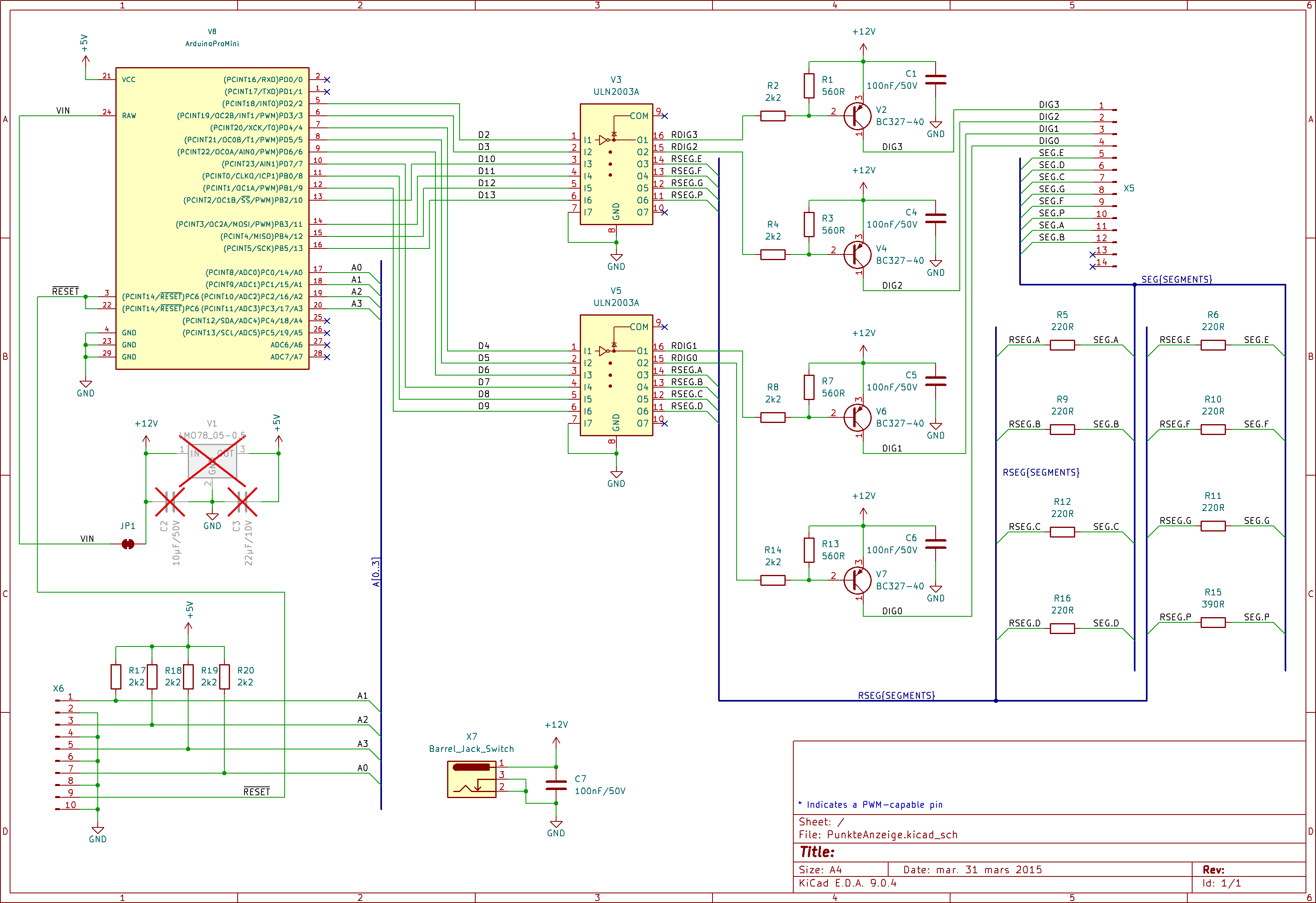
Schaltplan einer LED-Ansteuerung mit ULN2003A
VIN, VCC, +5V, (PCINT18/AD0)/PWM0, (PCINT17/AD1)/PWM1, (PCINT16/AD2)/PWM2, (PCINT15/AD3)/PWM3, (PCINT14/AD4)/PWM4, (PCINT13/AD5)/PWM5, (PCINT12/AD6)/PWM6, (PCINT11/AD7)/PWM7, RESET, GND, V1, 10nF, 22pF, X6, R17, R18, R19, R20, 2k2,
in „7-Segment LEDs ansteuern“ · Mikrocontroller und Digitale Elektronik · · Schaltpläne
-
PDF
Datenblatt_EBMPapstLuefter.pdf
16 Product Data Sheet 4114 N/2H7P 3 Operating Data 3.1 Electrical Interface - Input Control input PWM Features Inpute type Open collector PWM - Frequency 1 kHz - 20 kHz Characteristics Schematics Speed control: PWM = 0...100 %; f = 1...20 kHz; n = 500...9500 1/min 01/31/2019 page 5 of 16 Product Data
in „EBM Papst 4114 Lüfter mit Microcontroller steuern“ · Analoge Elektronik und Schaltungstechnik ·
-
Datei
ProgrammV2.asm
1<<ADEN) | (1<<ADPS2) | (0<<ADPS1) | (1<<ADPS0) out ADCSRA, temp1 ;--------------------------------PWM Initialisierung-------------------------------------- ;PWM initialisieren 14Fast PWM Betrieb ldi temp1, (1<<COM1A1)|(1<<WGM11)|(0<<WGM10) out TCCR1A, temp1 ldi temp1, (1<<WGM13) | (1<<WGM12) | (1<<CS10
in „Analog zu PWM. Fehler im Programm?“ · Mikrocontroller und Digitale Elektronik ·
-
Datei
Source.txt
baud = 38400 Config Portb.1 = Output Config Portb.2 = Output Config Portb.3 = Output Config Timer1 = Pwm , Pwm = 8 , Compare A Pwm = Clear Down , Compare B Pwm = Clear Down , Prescale = 1 Config Timer2 = Pwm , Pwm = On , Compare Ocr2 Pwm = Clear Up , Prescale = 1 Start Timer1 Start Timer2 Enable Interrupts
in „RGB-LED-Steuerung in BASCOM per PC RS232“ · Projekte & Code ·
-
Datei
Source.txt
baud = 38400 Config Portb.1 = Output Config Portb.2 = Output Config Portb.3 = Output Config Timer1 = Pwm , Pwm = 8 , Compare A Pwm = Clear Down , Compare B Pwm = Clear Down , Prescale = 1 Config Timer2 = Pwm , Pwm = On , Compare Ocr2 Pwm = Clear Up , Prescale = 1 Start Timer1 Start Timer2 Enable Interrupts
in „RS232 RGB Led Steuerung geht nicht.“ · Mikrocontroller und Digitale Elektronik ·
-
PDF
MEGA_LAMP.pdf
+12V +5V IC1 +12V E W IN OUT 2 O F N B 4 K P N G N G K 2 0 78S05 3 R C 1 C 1 T1 PWM1 BS170 +12V T2 S 3 E K W PWM2 M BS170 P E T4 E +5V / V BS170 + R1 IC2 PC6 PC5 TSOP1738 IC3 / PD0 PC4 T3 1 X 4k7 PC3 K R PD1 PC2 V PD2 PC1 PWM3/MOSI + PWM4 PD3 BS170 PD4 PC0 VCC GND GND AREF PB6 AVCC PB7 PB5 5 PWM2 PD5 PB4 + PWM1 PD6 PB3 PWM3/MOSI PD7 PB2 MISO PB1 SCK PB0 0 V + C1 100NF +5V K5 PWM3/MOSI /RESET SCK Maßstab100,00% Firma Zeichner Blatt MISO Änderung Titel ISP 27.07.08 17:36 Ausgabe 14.08.08 22:18
in „[Projekt] MEGA Lamp“ · Mikrocontroller und Digitale Elektronik ·
-
Datei
AVR_SPS.c
) if(Z<999) Z++; //Zähle vorwärts (KoF) #define ZR(Z) if(Z>0) Z--; //Zähle rückwärts (KoF) #define PWM1(byte) OCR1AL = byte //PWM-Kanal 1 (KoF) #define PWM2(byte) OCR1BL = byte //PWM-Kanal 2 (KoF) int8_t VK, VKH; //Verknüpfungsspeicher und Hilfverknpfungsspeicher uint8_t E0; //Ein-Ausgäge , Merker,Sondermerker
in „AVR Studio + Simulation“ · Mikrocontroller und Digitale Elektronik ·
-
Datei
softpwm.txt
reset: ;Stackpointer initialisieren: ldi wl,low(ramend) out SPL,wl ldi wl,high(ramend) out SPH,wl ;PWM-Ausgänge (LEDs) initialisieren: ldi wl, 0xff ;Port für LEDs (PWM-Ausgänge) out lep-1,wl ;= Ausgang (DDRx=PORTx-1) ;Tasten-Eingänge initialisieren: ldi wl, alltast ;pull-ups für Tasten out tap+2,wl ;
in „PWM IM SRAM MEGA8515“ · Mikrocontroller und Digitale Elektronik ·