-
Datei
Test.c
Pins von Port C als Ausgang */ DDRD = 0x00; /* alle Pins von Port D als Eingang */ PORTB = 0x00; PORTC = 0x00; PORTD = 0xff; /* interne Pull-Ups an allen Port-Pins aktivieren */ /* Hauptprogrammschleife */ while(1) { /* Zeit abrufen */ /* UTC-Zeit Umwandlung und Ausgabe */ for (i=0; i<=5; i++) { utc[i] = Zeit[i]-'0'; PORTB = 15; PORTC = utc[i]; PORTB = i+4; } // UTC-Variablen errechnen utc_h = utc[0] * 10 + utc[1]; utc_m = utc[2] * 10 + utc[3]; utc_s = utc[4] * 10 + utc[5]; /* // CHR-Zeit Berechnung if (chr_run) { if(chr_h_start
in „Atmel Mega 8 verhält sich nicht wie in AVR Studio Simulation“ · Mikrocontroller und Digitale Elektronik ·
-
Datei
final_program_endgueltig.c
fail_sound(void){ static uint16_t hilf = 200; if (hilf > 100 && hilf <= 200) { /* Frequenz ca. 391Hz */ PORTC |= (1 << PC6); _delay_ms(1.28); PORTC &= ~(1 << PC6); _delay_ms(1.28); } else if (hilf > 0 && hilf <= 100) { /* Frequenz ca. 132Hz */ PORTC |= (1 << PC6); _delay_ms(3.8); PORTC &= ~(1 << PC6); _delay_ms
in „Programmoptimierung“ · Mikrocontroller und Digitale Elektronik ·
-
Datei
speed.c
Alphanumeric LCD Module functions #asm .equ __lcd_port=0x12 ;PORTD #endasm #include <lcd.h> #define CS PORTC.3 #define SCLK PORTC.4 #define AN 0 #define AUS 1 // Timer 1 overflow interrupt service routine interrupt [TIM1_OVF] void timer1_ovf_isr(void) { // Place your code here } void Anzeige(int Einzelzahl
in „schnelle Speichererweiterung für ATmega128“ · Mikrocontroller und Digitale Elektronik ·
-
Datei
lcd-routines.h
aber an einer // beliebigen Postion anfangen #ifndef LCD_PORTS #define LCD_PORTS #define LCD_PORT PORTC #define LCD_DDR DDRC // 4 Bit LCD Datenbus DB4-DB7, das unterste Bit DB4 kann auf den Portbits 0..4 liegen // LCD DB4-DB7 <--> PORTC Bit PC0-PC3 #define LCD_DB PC4 // LCD Steuersignale RS und EN // LCD RS <--> PORTC Bit PC4 (RS: 0=Data, 1=Command) #define LCD_RS PA4 // LCD EN <--> PORTC Bit PC5 (EN: 1-Impuls für Daten) #define LCD_EN PD3 #endif // LCD_PORTS /////////////////////////////////////////////////////
in „LCD AV0820 Ansteuerung nicht möglich, nur flimmernde Kästchen“ · Mikrocontroller und Digitale Elektronik ·
-
Datei
lcd.h
aber an einer // beliebigen Postion anfangen #ifndef LCD_PORTS #define LCD_PORTS #define LCD_PORT PORTC #define LCD_DDR DDRC #define LCD_CTRL PORTD // meine Steuerleitungen sind auf einem anderen Port // 4 Bit LCD Datenbus DB4-DB7, das unterste Bit DB4 kann auf den Portbits 0..4 liegen // LCD DB4-DB7 <--> PORTC Bit PC0-PC3 #define LCD_DB PC4 // LCD Steuersignale RS und EN // LCD RS <--> PORTC Bit PC4 (RS: 0=Data, 1=Command) #define LCD_RS PD3 // LCD EN <--> PORTC Bit PC5 (EN: 1-Impuls für Daten) #define LCD_EN
in „HD44780 LCD - Simulation OK, AVR bleibt in Funktionen stecken“ · Mikrocontroller und Digitale Elektronik ·
-
Datei
code.txt
AMPEL2_ROT); PORTD &= ~(1 << AMPEL1_GRUN); PORTD &= ~(1 << AMPEL2_GRUN); PORTD &= ~(1 << MOTOR); PORTC &= ~(1 << VENTIL); OR_LED_En = 1; Sirene_En = 1; Status_En = 1; } } void LKWWeg(void) { PORTD |= (1 << AMPEL1_ROT); PORTD |= (1 << AMPEL2_GRUN); PORTD &= ~(1 << AMPEL1_GRUN); PORTD &= ~(1 << AMPEL2
in „Problem mit ADC & Tipps zum Code?“ · Mikrocontroller und Digitale Elektronik ·
-
Datei
usart_main.asm
temp ;Inhalt von r16 ins IO-Register DDRB ausgeben ldi led, 0b10000000 ;0b11111100 in r16 laden out PORTC, led ;r16 ins IO-Register PORTB ausgeben ldi temp, LOW(RAMEND) ;Stackpointer initialisieren out SPL, temp ldi temp, HIGH(RAMEND) out SPH, temp call USART_init ldi temp, 0b01000111 ;Messbereich 0-5V
in „USART asm ATmega32 mehrere bytes empfangen?“ · Mikrocontroller und Digitale Elektronik ·
-
Datei
Forum.c
= (1<<PD7 | 1<<PD6 | 1<<PD5 | 1<< PD4 | 1<<PD3 | 1<<PD2 | 1<<PD1 | 1<<PD0); //Servos 0-7 auf High PORTC |= (1<<PC0); //PC0 = Servo 8 auf High if (oeffnen==1) //ersten OCR1B Wert setzen je nachdem ob Fahrwerk offen oder zu { OCR1B = servos_open[0].when; //Beim Timerdurchlauf Top quasi Bottom wird immer
in „Debug-Problem in AVR-Studio 5“ · Mikrocontroller und Digitale Elektronik ·
-
Datei
sms_alarm_laden_002_20110414_-_Kopie.c
, es wird gegen Masse geschalten DDRC=0b11111111; //Ports C als Ausgang für Melderrücksetzung 0-7 PORTC=0b00000000; //alle Ausgänge PortC auf low LADEDATAREGISTER=LADEDATAREGISTER |= (1<<LADEPIN); //Ausgang für Handyladegerät festlegen LADEPORT=LADEPORT &= ~(1<<LADEPIN); //Ausgang Handyladegerät auf
in „bis 30 Minuten zählen“ · Mikrocontroller und Digitale Elektronik ·
-
Datei
lcd-routines.h
aber an einer // beliebigen Postion anfangen #ifndef LCD_PORTS #define LCD_PORTS #define LCD_PORT PORTC #define LCD_DDR DDRC // 4 Bit LCD Datenbus DB4-DB7, das unterste Bit DB4 kann auf den Portbits 0..4 liegen // LCD DB4-DB7 <--> PORTC Bit PC0-PC3 #define LCD_DB PC1 // LCD Steuersignale RS und EN // LCD RS <--> PORTC Bit PC4 (RS: 0=Data, 1=Command) #define LCD_RS PC6 // LCD EN <--> PORTC Bit PC5 (EN: 1-Impuls für Daten) #define LCD_EN PC5 #endif // LCD_PORTS /////////////////////////////////////////////////////
in „Display Ansteuerung - 16 x 4 DotMatrix LCD“ · Mikrocontroller und Digitale Elektronik ·
-
Datei
lcd-routines.h
aber an einer // beliebigen Postion anfangen #ifndef LCD_PORTS #define LCD_PORTS #define LCD_PORT PORTC #define LCD_DDR DDRC // 4 Bit LCD Datenbus DB4-DB7, das unterste Bit DB4 kann auf den Portbits 0..4 liegen // LCD DB4-DB7 <--> PORTC Bit PC0-PC3 #define LCD_DB PC1 // LCD Steuersignale RS und EN // LCD RS <--> PORTC Bit PC4 (RS: 0=Data, 1=Command) #define LCD_RS PC6 // LCD EN <--> PORTC Bit PC5 (EN: 1-Impuls für Daten) #define LCD_EN PC5 #endif // LCD_PORTS /////////////////////////////////////////////////////
in „DotMatrix 16x4 in C ansteuern“ · Mikrocontroller und Digitale Elektronik ·
-
Datei
main.c
STAT_UART_REC)) | (PINC & (1<<TASTER)))) { } } } ISR(TIMER0_OVF_vect) { if (status & (1<<STAT_MOTOR_AN)) { PORTC ^= (1<<SCHRITT); weg++; } zeit++; } ISR(USART_RXC_vect) { if (!(status & (1<<STAT_UART_REC))) { empfangen = UDR; status |= (1<<STAT_UART_REC); } } int uart_putc(unsigned char c) { while (!(UCSRA &
in „Atmega 8; EEPROM bei Reset korrumpiert; alle 0 werden zu 255“ · Mikrocontroller und Digitale Elektronik ·
-
Datei
LCD.h
aber an einer // beliebigen Postion anfangen #ifndef LCD_PORTS #define LCD_PORTS #define LCD_PORT PORTC #define LCD_DDR DDRC // 4 Bit LCD Datenbus DB4-DB7, das unterste Bit DB4 kann auf den Portbits 0..4 liegen // LCD DB4-DB7 <--> PORTC Bit PC0-PC3 #define LCD_DB PC4 // LCD Steuersignale RS und EN // LCD RS <--> PORTC Bit PC4 (RS: 0=Data, 1=Command) #define LCD_RS PC2 // LCD EN <--> PORTC Bit PC5 (EN: 1-Impuls für Daten) #define LCD_EN PC3 #endif // LCD_PORTS /////////////////////////////////////////////////////
in „Problem Mit LCD display“ · Mikrocontroller und Digitale Elektronik ·
-
Datei
SED133x_v2.bas
Gosub Lcd_write_pixel $regfile = "4433def.dat" $crystal = 8000000 Ddrd = $ff Portd = 255 Ddrc = $ff Portc = 255 Lcd_io_a0 Alias Portc.0 ' SED A0 (C/D) Lcd_io_cs Alias Portc.1 ' SED /CS Lcd_io_wr Alias Portc.2 ' SED /WR Lcd_io_rd Alias Portc.3 ' SED /RD Lcd_io_out Alias Portd ' SED 8 bit data Lcd_io_dir
in „Ansteuerung Grafikdisplay mit SED133x in BASCOM“ · Projekte & Code ·
-
Datei
temp_zum_pc.asm
****************************************** write_1: ;schreibt eine 1 sbi ddrc, 0 ;PB0 Ausgang cbi portc, 0 ;bus auf low rcall wait6us ;wartet 8us (maximum sind 15us) cbi ddrc, 0 ;lässt bus los, nun durch ext R auf high rcall wait64us ;slot muss mind. 60us lang sein ret ;******************************
in „Temperatur DS1820 ausgabe auf lcd“ · Mikrocontroller und Digitale Elektronik ·
-
Datei
Blackstorm_Atmega8_2.bas
' Ein-/Ausgänge Config Portd = Output 'Port D als Ausgang Ddrc = &B00111100 '1 Ausgang, 0 Eingang Portc = &B1000011 '1 = PullUp aktiviert Eingang (Taster gegen Masse) Ddrb = &B00011111 Portb = &B00000000 'zum Stoppen (Zeitmessen) Portb = &B000010 Sek_blink = 1 'Ausgänge: Segment_a Alias Portd.0 Segment_b
in „Attiny13 Schalter“ · Mikrocontroller und Digitale Elektronik ·
-
Datei
CDPLAYER.ASM
nop ldi temp, 0b10111111 ; Statusregister adressieren out Portd, temp Rcall inPC ; PortC wieder auf Input ldi temp, 0b10111110 out PortD, temp ; Statusregister lesen nop loop03: Sbic PinC,0x07 ; Warte, bis Busy=0 Rjmp loop03 Sbis PinC,0x03 ; Warte, bis DRQ=1 Rjmp loop03 ;**************
in „CD Laufwerk: packet command“ · Mikrocontroller und Digitale Elektronik ·
-
Datei
dcf-clock.c
PB0,1,2 Ausgang (1) DDRC |= (1<<DDB4) | (1<<DDB5); //PC4,5 Ausgang (1) //Initialisieren der Ports // PORTC |= (1<<PC1); //PC1 Pull-Up gesetzt (1) // PORTC |= (1<<PC4) | (1<<PC5); // _delay_ms(5000); PORTC &= ~((1<<PC4) | (1<<PC5)); lcd_init(); //Initialisierung des LCDs _delay_ms(300); // Timer 0 konfigurieren
in „Terrariensteuerung: DCF & 1-Wire zugleich?“ · Mikrocontroller und Digitale Elektronik ·
-
Datei
Cynetik.c
nicht anzeigen } void cap_button (void) { if (PIND & 0x04) { long_delay (40); if (!(PINC & 0x04)) { PORTC = 0xF7; out = 0; } else if (!(PINC & 0x08)) { PORTC = 0xEF; out = 1; } else if (!(PINC & 0x10)) { PORTC = 0xDF; out = 2; } else if (!(PINC & 0x20)) { PORTC = 0xBF; out = 3; } else if (!(PINC & 0x40)) { PORTC = 0x7F; out = 4; } else if (!(PINC & 0x80)) { PORTC = 0xFB; out = 5; } } } void ADC_Init (void) { ADMUX = (1<<REFS0)|(1<<ADLAR); ADCSRA = (1<<ADPS2)|(1<<ADPS0); ADCSRA |= (1<<ADEN); ADCSRA |= (1<<ADSC
in „AD-Wandler im ATmega8535“ · Mikrocontroller und Digitale Elektronik ·
-
Datei
m16def.inc
Pins bit 5 .equ PINB6 = 6 ; Port B Input Pins bit 6 .equ PINB7 = 7 ; Port B Input Pins bit 7 ; ***** PORTC ************************ ; PORTC - Port C Data Register .equ PORTC0 = 0 ; Port C Data Register bit 0 .equ PC0 = 0 ; For compatibility .equ PORTC1 = 1 ; Port C Data Register bit 1 .equ PC1 = 1 ; For compatibility .equ PORTC2 = 2 ; Port C Data Register bit 2 .equ PC2 = 2 ; For compatibility .equ PORTC3 = 3 ; Port C Data Register bit 3 .equ PC3 = 3 ; For compatibility .equ PORTC4 = 4 ; Port C Data Register bit 4 .equ PC4
in „avra woher die ***def.inc dateien nehmen?“ · Mikrocontroller und Digitale Elektronik ·
-
Datei
m16def.inc
Pins bit 5 .equ PINB6 = 6 ; Port B Input Pins bit 6 .equ PINB7 = 7 ; Port B Input Pins bit 7 ; ***** PORTC ************************ ; PORTC - Port C Data Register .equ PORTC0 = 0 ; Port C Data Register bit 0 .equ PC0 = 0 ; For compatibility .equ PORTC1 = 1 ; Port C Data Register bit 1 .equ PC1 = 1 ; For compatibility .equ PORTC2 = 2 ; Port C Data Register bit 2 .equ PC2 = 2 ; For compatibility .equ PORTC3 = 3 ; Port C Data Register bit 3 .equ PC3 = 3 ; For compatibility .equ PORTC4 = 4 ; Port C Data Register bit 4 .equ PC4
in „ATMega16 mehrere Taster an INT0“ · Mikrocontroller und Digitale Elektronik ·
-
Datei
Taster.txt
$regfile "m8def.dat" $crystal = 4000000 Config Portb = Input Config Portc = Output Do If Portb.0 = 0 Then Portc.0 = 1 Else Portc.0 = 0 End If Loop End
in „Bascom Problem“ · Mikrocontroller und Digitale Elektronik ·
-
Datei
lcd.bas
$Device = 8535 $Clock = 8 $Source= On $Stack = 32 $Lcd=PORTC.4, rs=PORTC.0, en=PORTC.2, 16,20 'DDRC=255 Enable Interrupts Cls Wait 2 Dim a As Integer Do Incr a Locate 1,1 Lcd a Loop End
in „Fastavr PWM-Signal“ · Mikrocontroller und Digitale Elektronik ·
-
Datei
FTB_main.c
#include <io.h> int main (void) { outp( 0x20, DDRC ); for (;;) { if ( bit_is_set(PORTC, PINC0) ) sbi( PORTC, PINC5 ); // Laterne anknipsen else cbi( PORTC, PINC5 ); // Laterne ausknipsen } }
in „Taste auswerten“ · Mikrocontroller und Digitale Elektronik ·
-
Datei
lcd.bas
$Device = mega128 $Clock = 8 $Source= On $Stack = 32 $Baud = 19200,n,8,1 $Lcd=PORTC.4, rs=PORTC.0, en=PORTC.2, 16,20 Enable Interrupts Cls Dim s As String * 20 Do Input S Lcd s Loop End
in „Fastavr PWM-Signal“ · Mikrocontroller und Digitale Elektronik ·
-
Datei
main.c
int main(void) { unsigned int i,j,k; DDRC = 0xFF; while(1) { /*Initialisierung Lauflicht*/ i = 1; PORTC = 0x01; while(i<=8) { /*Zeitschleife*/ for(j=0;j<5000;j++) { for(k=0;k<5000;k++); } PORTC=PORTC*2; i++; } } return 0; }
in „Timer 0 mit t=500ms“ · Mikrocontroller und Digitale Elektronik ·
-
Datei
Input-Output.bas
baud = 9600 'Baudrate der Schnittstelle $crystal = 14300000 'Schwingungsfrequenz des Quarzes Config Portc = Input Config Porta = Output Do If Portc.1 = 1 Then Porta.0 = 0 Print "0" Elseif Portc.1 = 0 Then Porta.0 = 1 Print "1" Else Print "nix" End If Loop
in „Bascom Code“ · Mikrocontroller und Digitale Elektronik ·
-
Datei
t6963_BITMAP.c
, 00, 00, 00, 00, 00, 00, 00, 00, 00, 00, 00, 00, 00, 00, 00, 00, 00, 00}; void pause(void); void PORTC_output(void); void PORTC_input(void); void out(char commando,char dataa, char datab); void lcd_status(void); void autoreset(void); void autowrite(void); void t6963cinit(void); void lcd_PutPixel(unsigned
in „BITMAP darstellen auf GLCD“ · Mikrocontroller und Digitale Elektronik ·
-
Datei
DCF_Alarm_nodcf.bas
Alarm_berechnung Case 6 Locate 3 , 1 : Lcd "================" If Pinc.3 = 0 Then Incr Stellp If Stellp = 10 Then Portc.3 = 0 Portc.2 = 0 End If Call Alarm_berechnung Case 7 Locate 3 , 1 : Lcd "====ENDE========" Waitms 100 Call Alarm_berechnung Case 8 Locate 3 , 1 : Lcd "=====ENDE=======" Waitms 100 Call Alarm_berechnung
in „µc resetet sich?“ · Mikrocontroller und Digitale Elektronik ·
-
Datei
avr8_servos.c
servo_abs[maxservos+1]; void servoset_generell (void) { uint8_t count; servo_gen[0].adr =0x15; /*PORTC (als _SFR_IO8(0x15) benutzen*/ servo_gen[0].pin = PC0; servo_gen[0].absmax =carsm_max; servo_gen[0].absmin =carsm_min; servo_gen[1].adr =0x15; /*PORTC (als _SFR_IO8(0x15) benutzen*/ servo_gen[1].pin =PC1; servo_gen[1].absmax =carsm_max; servo_gen[1].absmin =carsm_min; servo_gen[2].adr =0x15; /*PORTC (als _SFR_IO8(0x15) benutzen*/ servo_gen[2].pin =PC2; servo_gen[2].absmax =carsm_max; servo_gen[2].absmin =carsm_min; servo_gen[3].adr =0x15; /*PORTC (als _SFR_IO8(0x15) benutzen*/ servo_gen[3].pin
in „Servocontroller mit ATmega8 für 20 Servos“ · Projekte & Code ·
-
Datei
index.htm
="%PORTC3"><INPUT TYPE="hidden" NAME="OUT" VALUE="H"><INPUT TYPE="submit" VALUE="Schalter C3" NAME="SUB"></p> </form> <form name=form1 method=post action=> <p align=center><img border=0 width=17 height=17 src
in „AVR Net-IO auf 3,3V“ · Mikrocontroller und Digitale Elektronik ·
-
Datei
Handy-Waehlscheibe_V0.30c_Layout.bas
------------------------ Portd.2 = 1 'PullUp Portb.3 = 1 'PullUp Portb.5 = 1 'PullUp Portb.4 = 1 'Portc.4 = 1 Gabel Alias Pinb.2 'Gabel-Schalter Gabel = 1 = unten Ring_h Alias Pinb.3 'Klingensignal vom Handy Wahl_puls Alias Pinb.5 'Wähler PULS Wahl_en Alias Pinb.4 'Wähler EN 'Batt Alias Pinc.5 'AD-Wandler
in „ATMega88V-Schaltung: 20% Fehlverhalten“ · Mikrocontroller und Digitale Elektronik ·
-
Datei
Handy-Waehlscheibe_V0.30c_Layout.bas
------------------------ Portd.2 = 1 'PullUp Portb.3 = 1 'PullUp Portb.5 = 1 'PullUp Portb.4 = 1 'Portc.4 = 1 Gabel Alias Pinb.2 'Gabel-Schalter Gabel = 1 = unten Ring_h Alias Pinb.3 'Klingensignal vom Handy Wahl_puls Alias Pinb.5 'Wähler PULS Wahl_en Alias Pinb.4 'Wähler EN 'Batt Alias Pinc.5 'AD-Wandler
in „ATMega88V-Schaltung: 20% Fehlverhalten“ · Mikrocontroller und Digitale Elektronik ·
-
Datei
Strichbreite10.bas
Portd.7 = 1 Marke2_aus Alias Pind.7 Config Portb.0 = Output 'Umschaltung Sweep Hold 1=1ms Config Portc.2 = Input 'erweiterung Vers.10 1=0-1300MHz Portc.2 = 0 'erweiterung Vers.10 0=0-50MHz Bereich Alias Pinc.2 'erweiterung Vers.10 Config Portc.3 = Input 'erweiterung Vers.10 0=0-2MHz Portc.3 = 0 'erweiterung
in „mit Bascom über rs232 Frequenz aus einen Frequenzzählermodul auslesen.“ · Mikrocontroller und Digitale Elektronik ·
-
Datei
Strichbreite11.bas
Portd.7 = 1 Marke2_aus Alias Pind.7 Config Portb.0 = Output 'Umschaltung Sweep Hold 1=1ms Config Portc.2 = Input 'erweiterung Vers.10 1=0-1300MHz Portc.2 = 0 'erweiterung Vers.10 0=0-50MHz Bereich Alias Pinc.2 'erweiterung Vers.10 Config Portc.3 = Input 'erweiterung Vers.10 0=0-2MHz Portc.3 = 0 'erweiterung
in „mit Bascom über rs232 Frequenz aus einen Frequenzzählermodul auslesen.“ · Mikrocontroller und Digitale Elektronik ·
-
 Bild
Bild
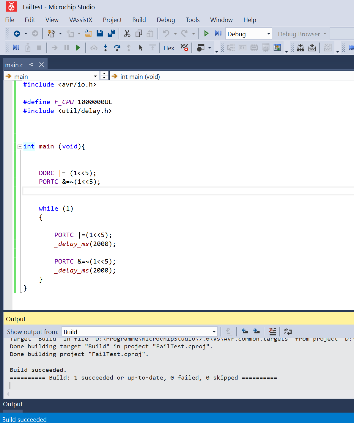
Screenshot von Microchip Studio mit C-Code
main (void) { #include <avr/io.h> #define F_CPU 1000000UL #include <util/delay.h> DDRC |= (1<<5); PORTC &= ~(1<<5); while (1) { PORTC |= (1<<5); _delay_ms(2000); PORTC &= ~(1<<5); _delay_ms(2000); } } Output Build succeeded.
in „Atmega328 U(?) Prüfsummen Fehler“ · Mikrocontroller und Digitale Elektronik · · Screenshots
-
Datei
TimerCnt_test.c
inttypes.h> #ifndef F_CPU #define F_CPU 3686400UL /* Quarz mit 3.6864 Mhz */ #endif ISR(TIMER0_OVF_vect) { PORTC|=(1<<1); } int main(void) { sei(); DDRC=0xff; TCNT0=0; TCCR0|= (1<<CS00) ; while (1) { PORTC|=(1<<0); PORTC&=~(1<<0); } }
in „Warum wird nicht in meine Interrupt Routine gesprungen?“ · Mikrocontroller und Digitale Elektronik ·
-
Datei
st_test.c
/ outp(0xff, DDRB); /* Port B als Ausgang*/ outp(0x00, DDRC); /* Port C als Eingang */ outp(0xff, PORTC); /* Port C als Eingang */ outp(0xc0, DDRD); /* Port D PIN 6 und 7 als Ausgang */ /* Port D PIN 1 bis 5 als Eingang */ outp(0xc0, PORTD); } /* ******************************************************
in „region text is full“ · Mikrocontroller und Digitale Elektronik ·
-
Datei
main.c
void prepread() { oc0_off(); mux(MUX_SOFT); we_off(); gate_off(); DDRA = 0; DDRC = 0; PORTA = 0xff; PORTC = 0xff; oe_on(); } void prepgate() { oc0_off(); mux(MUX_SOFT); we_off(); oe_off(); DDRA = 0; DDRC = 0; PORTA = 0xff; PORTC = 0xff; gate_on(); } void preprecord() { mux(clock_source); if (clock_source == MUX_SOFT) oc0_on(); else oc0_off(); oe_off(); DDRA = 0; DDRC = 0; PORTA = 0; PORTC = 0; gate_on(); we_on(); } void put(unsigned int value) { PORTA = (value >> 8 ) & 0xff; PORTC = value & 0xff; ch(); cl(); } unsigned int get() { ch(); cl(); return PINC + (PINA << 8) ; } void fill(
in „8 Kanal 50Ms/s AVR Logic-Analyzer“ · Mikrocontroller und Digitale Elektronik ·
-
Datei
Quellz_hler.txt
Ausgang Digit4 sbi DDRC,1 ;Ausgang Digit3 sbi DDRC,2 ;Ausgang Digit2 sbi DDRC,3 ;Ausgang Digit1 out PORTC,temp ;alle Digits aus ; ;Init Timer 0 ; ldi temp,0b00000101 ;Vorteiler 1024 out TCCR0,temp ldi temp,0b00000001 ;Timer 0 überlauf out TIMSK,temp ; ;Init Watchdog ; ;rcall WD_init ; ; ;Register vereinbaren
in „7 Segment mit flimmern“ · Mikrocontroller und Digitale Elektronik ·
-
Datei
solar.c
Timeroverflowinterrupt für das Multiplexen der 4 7-Segment Anzeigen*/ ISR(TIMER0_OVF_vect){ icount++; PORTC=0; PORTD=show[display[pos]]; PORTC|=(1<<pos); if(pos==0&&einspeisen==1) /*Punkt ob eingespeist wird oder nicht*/ PORTD&=~(1<<7); if(pos==1&&powered==1) /*Punkt ob WP gepowered oder nicht*/ PORTD&=~
in „Display fällt in unregelmäßigen Abständen aus“ · Mikrocontroller und Digitale Elektronik ·
-
Datei
Sowftware_ACK_Test.asm
equ test = 7 .def Daten = r17 ;Adresse vom LM75 = 1001001x ( 0=write / 1=read ) .macro SDA_HI sbi portc, sda .endmacro .macro SDA_LO cbi portc, sda .endmacro .macro SCL_HI sbi portc, scl .endmacro .macro SCL_LO cbi portc, scl .endmacro RESET: ;STACK initialisieren ldi r16, LOW(RAMEND) out SPL, r16 ldi
in „Blutrausch wegen i2c“ · Mikrocontroller und Digitale Elektronik ·
-
Datei
Sowftware_ACK_Test.asm
equ test = 7 .def Daten = r17 ;Adresse vom LM75 = 1001001x ( 0=write / 1=read ) .macro SDA_HI sbi portc, sda .endmacro .macro SDA_LO cbi portc, sda .endmacro .macro SCL_HI sbi portc, scl .endmacro .macro SCL_LO cbi portc, scl .endmacro RESET: ;STACK initialisieren ldi r16, LOW(RAMEND) out SPL, r16 ldi
in „eDip 240 über SPI ansteuern“ · Mikrocontroller und Digitale Elektronik ·
-
Datei
Steuerung.bas
= 0 $lib "Lcd_i2c.lib" $lib "i2c_twi.lbx" Const Pcf8574_lcd = &H40 Enable Interrupts Config Scl = Portc.5 Config Sda = Portc.4 Dim _lcd_e As Byte , Relais As Byte , Command As Byte , X As Byte Dim Schritt As Byte , Command6 As Byte , Command0 As Byte , Y As Byte Dim I As Byte , Empf As Byte , First As
in „Bascom Problem mit 16Mhz Quartz“ · Mikrocontroller und Digitale Elektronik ·
-
Datei
test.c
macht // cli(); // interrupts aus DDRC = 0x00 | (1<<PC5); // alles eingänge bis auf pc5 ( reset ) PORTC &= ~(1 << RST_PIN); // reset auf low PORTD |= (1 << RST_LED);// led an _delay_ms(200); PORTC |= (1 << RST_PIN); // set reset high .. oder als input ? DDRC = 0x00; // alles eingänge PORTC = 0xff; //
in „Interrupt an INT0 und 1“ · Mikrocontroller und Digitale Elektronik ·
-
Datei
DAC_Entspurt.bas
regfile = "m8Adef.dat" $crystal = 8000000 $hwstack = 40 $swstack = 16 $framesize = 32 Config 1wire = Portc.3 Config Portd.0 = Output Config Portd.1 = Output Config Portd.2 = Output Config Portd.3 = Output Config Portd.4 = Output Config Portd.5 = Output Config Portd.6 = Output Config Portd.7 = Output Config Portb.0 = Output Config Portb.1 = Output Config Portb.2 = Output Config Portc.0 = Input Config Portc.1 = Input Config Portc.2 = Input Kontakt1 Alias Pinc.0 Kontakt2 Alias Pinc.1 Kontakt3 Alias Pinc.2 Config Timer1 = Timer , Prescale = 1024 Enable Timer1 On Timer1 Isr_von_t1
in „Thermomter DS18b20“ · Mikrocontroller und Digitale Elektronik ·
-
PDF
CF-Karte.pdf
von CF-, SD-Karten (AVR-DOS). Auch hier wieder die entsprechenden Definitionen: ' Daten ECB Config Portc = Input ' Handshake ECB Config Portd.2 = Input Config Portd.3 = Input Config Portd.4 = Output Config Portd.5 = Output Hs_obf Alias Pind.2 ' /OBF ' Hs_ibf Alias Pind.3 ' IBF Hs_ack Alias Portd.4 ' /
in „Suche MOPPEL Projekt in Heft oder .PDF“ · Mikrocontroller und Digitale Elektronik ·
-
Datei
Atmega64_mit_4xLS7060_in_MHz__MCP3204-Version2-20-09-2017-1.bas
Input 'SP4 Config Pinc.3 = Input 'SP3 Config Pinc.4 = Input 'SP2 Config Pinc.5 = Input 'SP1 Config Portc.6 = Output 'OSC_OFF Config Pinc.7 = Input 'SP7 Portc.0 = 1 Portc.1 = 1 'Pullup-Widerstände einschalten Portc.2 = 1 Portc.3 = 1 Portc.4 = 1 Portc.5 = 1 Portc.7 = 1 Config Portd.0 = Input 'Trigger, PD2
in „Frequenzanzeige Spektrumanalyzer“ · HF, Funk und Felder ·
-
Datei
main.c
io.h> int init_ausgang(void) { /*outp(0xFF, DDRC); // Alle Ports von C als Output setzen outp(0xFF, PORTC); // Alle LEDs aus */ DDRC=(1<<DDC0); PORTC=(1<<DDC0); } int ausgabe(void) { PORTC=(0<<DDC0); } int main(void) { unsigned int keys; init_ausgang(); DDRA = 0x00; for (;;) { keys = PINA; if ( !(PINA
in „GCC - I/O problem + Tastatur - Blackout“ · Mikrocontroller und Digitale Elektronik ·
-
Datei
Programmcode.txt
#include <p18f2331.h> #include <timers.h> #include <pwm.h> void led_ein(void) { PORTC = 0x18; } void led_aus(void) { PORTC = 0; } void main(void) { OpenTimer2 (TIMER_INT_OFF & T2_PS_1_1); OpenPWM1 (0xAA); SetDCPWM1 (0xFF); TRISBbits.TRISB0 = 0; PORTBbits.RB0 = 0; TRISC = 0; PORTC =
in „Pic18F2331 Problem“ · Mikrocontroller und Digitale Elektronik ·