-
PDF
atmel-4952-standard-drivers-ata6836c_datasheet.pdf
23 DS OnL 5.2 On resistance Out= –600mA 1-4, 11- 2, 5, 8, 11, R DS OnH 1.8 A 16, 27, 28 20, 23 High-side output 5.3 leakage current VOut1-6 0V 1-4, 11- 2, 5, 8, 11, I –15 µA A (total quiescent all output stages off 16, 27, 28 20, 23 Out1-6 current see 1.1
in „Keine Open Load Meldung bei ata6836c und IFX9201SG!“ · Mikrocontroller und Digitale Elektronik ·
-
PDF
DS203V2.6_SCH.pdf
M M C R R T B B K K K K K K K K K 1 C B B B B B B B B A A A A A C A A AQ BT0 R58 1 5 9 3 3 6 4 3 3 8 7 2 1 3 1 1 1 2 2 2 2 2 2 2 2 2 2 1 1 1 1 1 1 5 4 1K1 9 8 9 9 5 5 6 6 6 6 7 7 6 6 7 7 8 7 8 77 3 1 9 9 9 9 9 9 9 9 8 8 8 8 8 8 8 8 7 7 74 LCM U10 QX5239B-20mA 4 Gnd Led1 8 33 LED1- D C K C D D C + C
in „Oszilloskop aus STM32 und FPGA“ · Mikrocontroller und Digitale Elektronik ·
-
Datei
readme.txt
einen Easy-PDK-Programmer Clone hatte ich bereits aufgebaut, aber eben wie der originale mit einem STM32F072 der momentan nur relativ teuer erhältlich ist – Stand 12.12.2020). Google-Ergebnisse geben da derzeit nur 2 Projekte aus, die nicht auf dem oben genannten Programmer basieren. Beide habe ich ausprobiert
in „Padauk PFS154 Programmer mit Arduino Uno / ATmega88 - 328“ · Projekte & Code ·
-
Datei
readme.txt
einen Easy-PDK-Programmer Clone hatte ich bereits aufgebaut, aber eben wie der originale mit einem STM32F072. Dieser ist derzeit nur relativ teuer erhaetlich – Stand 12.12.2020). Google-Ergebnisse geben da derzeit nur 2 Projekte aus, die nicht auf dem oben genannten Programmer basieren. Beide habe
in „Padauk PFS154 Programmer mit Arduino Uno / ATmega88 - 328“ · Projekte & Code ·
-
Datei
edm_test.c
edm_variables.h" #include "edm_test.h" #include "../../ioMapping.h" // Alle Ports und Pins #include "stm32f10x_gpio.h" extern uint16_t ADC1ConvertedValues[10]; volatile uint16_t gl_a; volatile uint16_t gl_b; /* Test der ADC-Routinen (Multiplex und Interrupt-Aufruf) */ void edm_test_adc(void) { printf_P
in „STM32: Suche Hilfe zu ADC“ · Mikrocontroller und Digitale Elektronik ·
-
Datei
edm_test.c
edm_variables.h" #include "edm_test.h" #include "../../ioMapping.h" // Alle Ports und Pins #include "stm32f10x_gpio.h" extern uint16_t ADC1ConvertedValues[10]; volatile uint16_t gl_a; volatile uint16_t gl_b; /* Test der ADC-Routinen (Multiplex und Interrupt-Aufruf) */ void edm_test_adc(void) { printf_P
in „STM32 - ADC-DMA1-IRQ-Handler macht Unsinn“ · Mikrocontroller und Digitale Elektronik ·
-
Datei
src.txt
meta name="csrf-param" content="authenticity_token" /> <meta name="csrf-token" content="9NNq1lP3nVRv8jC8E9BVXhcrg3BUYz/GqFskurfBvJ6FhkvKyOBPi/X/K49C0LT5zEDdik5wD+SoH6EwbqwcYg==" /> <script type="application/ld+json"> { "@context": "https://schema.org", "@type": "BreadcrumbList", "itemListElement": [{
in „Verweis/Referenzierung zu anderen Beiträgen“ · www.mikrocontroller.net ·
-
Datei
usb.c
DoubleBuffered) Bulk_In_B 64 Bytes Bulk_Out_A 64 Bytes (evtl. DoubleBuffered) Bulk_Out_B 64 Bytes Int_In 8 Bytes (hier nicht benutzt) Int_Out 8 Bytes (hier nicht benutzt) ----------------------- macht 400 Bytes anschließend EpTable (USB_BTABLE zeigt drauf) mit 4 Einträgen (Control, BulkIn, BuklOut, Int) zu
in „An W.S.: Läuft deine USB Implementierung auch auf STM32F303?“ · Mikrocontroller und Digitale Elektronik ·
-
PDF
Eltako_Funk_Inspektion_pub.pdf
beim Betätigen eines Tasters des FTS12EM am RS485 Ausgang: A5 5A 0B 05 70 00 00 00 00 00 00 0B 00 8B // Drücken A5 5A 0B 05 00 00 00 00 00 00 00 0B 00 1B // Loslassen A5 5A 0B 05 50 00 00 00 00 00 00 0C 00 6C // Drücken A5 5A 0B 05 00 00 00 00 00 00 00 0C 00 1C // Loslassen Vermutlich bildet der FTS12EM
in „Dimmer für den Verteilerschrank mit Steuerinterface“ · Haus & Smart Home ·
-
PDF
Eltako_Funk_Inspektion_pub.pdf
beim Betätigen eines Tasters des FTS12EM am RS485 Ausgang: A5 5A 0B 05 70 00 00 00 00 00 00 0B 00 8B // Drücken A5 5A 0B 05 00 00 00 00 00 00 00 0B 00 1B // Loslassen A5 5A 0B 05 50 00 00 00 00 00 00 0C 00 6C // Drücken A5 5A 0B 05 00 00 00 00 00 00 00 0C 00 1C // Loslassen Vermutlich bildet der FTS12EM
-
Datei
startup_stm32f10x_cl.c
/** ****************************************************************************** * @file startup_stm32f10x_cl.c * @author Coocox * @version V1.0 * @date 3/7/2011 * @brief STM32F10x Connectivity line Devices Startup code. * This module performs: * - Set the initial SP * - Set the vector table entries
in „Compiler überschreibt Speicherbereich von Malloc“ · Mikrocontroller und Digitale Elektronik ·
-
Datei
alt.txt
#include "stm32f4xx.h" /* Pinout 1 VSS GND 2 VDD VDD 3 nc nc 4 RS PD4 5 R/W PD5 6 E PD6 7 nc nc 8 nc nc 9 nc nc 10 nc nc 11 D4 PD0 12 D5 PD1 13 D6 PD2 14 D7 PD3 15 nc nc 16 nc nc */ int i=0; void initDisplay(void
in „STM32: Ich finde einfach keinen Fehler in meinem Code“ · Mikrocontroller und Digitale Elektronik ·
-
Datei
Adc.c
#include "Adc.h" #include "stm32f4xx_adc.h" void Adc_Init(void) { ADC_InitTypeDef ADC_InitStructure; ADC_CommonInitTypeDef ADC_CommonInitStructure; GPIO_InitTypeDef GPIO_InitStructure; RCC_APB2PeriphClockCmd(RCC_APB2Periph_ADC1,
in „STM32F4 Internal Reference“ · Mikrocontroller und Digitale Elektronik ·
-
 Bild
Bild
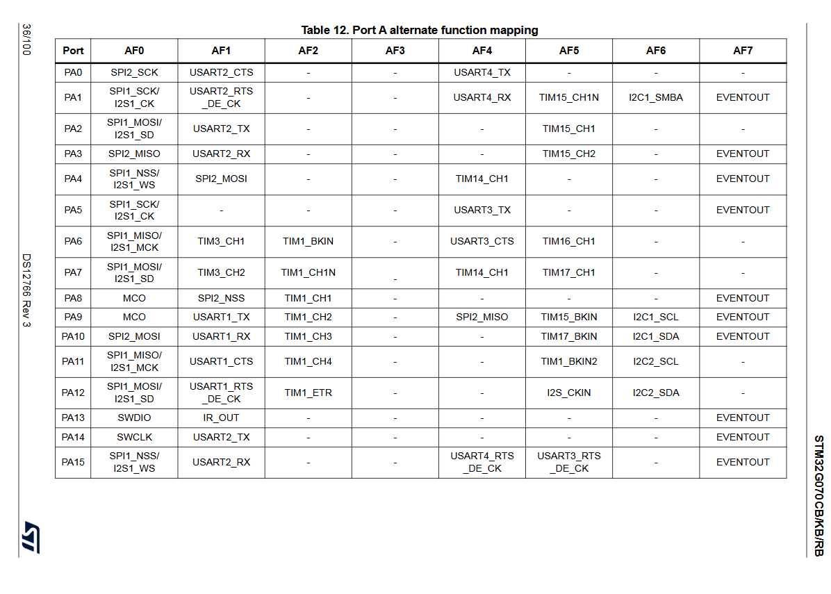
Tabelle der alternativen Port-Funktionszuweisungen eines Mikrocontrollers
- USART3_CTS TIM16_CH1 EVENTOUT PA7 SPI1_MOSI/I2S1_SD TIM3_CH2 TIM1_CH1 - TIM14_CH1 TIM17_CH1 - PA8 MCO SPI2_NSS TIM1_CH1 - - - EVENTOUT PA9 MCO USART1_TX TIM1_CH2 - SPI2_MISO TIM15_BKIN I2C1_SCL EVENTOUT PA10 SPI2_MOSI USART1_RX TIM1_CH3 - - TIM17_BKIN I2C1_SDA EVENTOUT PA11 SPI1_MISO/I2S1_MCK USART1
in „UART und I2C Konflikt mit STM32duino STM32G070“ · Mikrocontroller und Digitale Elektronik · · Screenshots
-
Datei
main.c
#include "stm32f0xx.h" #include <stdbool.h> #include <stdio.h> #include "main.h" // ---------------------------------------------------------------------------- /* * * RAM Bank of 5 23LC1024 SPI memory chips testing
in „SPI-RAM-Bank an STM32F0-Discovery - write, kein read“ · Mikrocontroller und Digitale Elektronik ·
-
Datei
main.c
eingelesen werden uint16_t ledMaxWidth = 0; //uint16_t T_SHUTTER_COMPLETE = 13 + ledMaxWidth; uint8_t ep1_address_write = 0x20; uint8_t ep2_address_write = 0x26; uint8_t ep3_address_write = 0x38; uint8_t ep4_address_write = 0x3E; uint8_t ep1_address_read = 0x21; uint8_t ep2_address_read = 0x27; uint8
in „stm32f303RE - initialisierungen verbeissen sich“ · Mikrocontroller und Digitale Elektronik ·
-
Datei
usb.c
DoubleBuffered) Bulk_In_B 64 Bytes Bulk_Out_A 64 Bytes (evtl. DoubleBuffered) Bulk_Out_B 64 Bytes Int_In 8 Bytes (hier nicht benutzt) Int_Out 8 Bytes (hier nicht benutzt) ----------------------- macht 400 Bytes anschließend EpTable (USB_BTABLE zeigt drauf) mit 4 Einträgen (Control, BulkIn, BuklOut, Int) zu
in „An W.S.: Läuft deine USB Implementierung auch auf STM32F303?“ · Mikrocontroller und Digitale Elektronik ·
-
PDF
TDA8375.pdf
S P D E S P E F T A E ) 4 H A 6 C S N V S R P D 5 6 M P 5 A ( 3 1 ( y ) E 9 3 m 3 9 U ( 3 o 4 ( H 8 n ook, full pagewidth ( 1 o 1 c ( 1 e ) d 8 S 2 0 e 8 ( R s A ( 1 l E A S S S - ) o S I D I I I N 5 8 t ) B C O B 6 B A ( 3 n 1 C S R × × × B / 9 o 7 ( 2I A N 1 1 1 W Y C S C ( 1 c T O S S I V I - C
in „PAL-Röhren TV auf NTSC umbauen“ · Analoge Elektronik und Schaltungstechnik ·
-
Datei
simple_server.c
**********************************************/ #include "..\main\include.h" #define PSTR(s) s //u8 st[10] ; u8 Pin8on = 1; u8 Pin9on = 0; //extern void delay_ms(u8 ms); // please modify the following two lines. mac and ip have to be unique // in your local area network. You can not have the same numbers
in „Webpage Webserver“ · Mikrocontroller und Digitale Elektronik ·
-
Datei
main.c
void SetupTimer(void); void USART1_SendString(char* data); // Global variables #define MAXSENSORS 8 uint8_t gSensorIDs[MAXSENSORS][9]; // 9=size of ROM codes // *************** main ************* int main(void) { char buffer[255]; sprintf(buffer,"this is the default value\n"); RCC_ClocksTypeDef RCC_Clocks
in „STM32 : Float linken mit Coocox“ · Mikrocontroller und Digitale Elektronik ·
-
PDF
small_pcb.PDF
PIVFD2536NC26 CO6 C7 led PIR10PIR1P01Iled02 VCC 3.3V VFD_SLEEP PIVFD2536SLEEP I2 22pF P72 22pF 10K PIVFD2536GND8 P01 PIVFD2536NC29 CO8 PIVFD2536GND0 P020.1uFPI8M01 PI8M02 PISTM32VBATRCT601 VDD PISTM32FVCC 3.3V64 PIVFD2536NC31 CO8M pwm1 PISTM32PC13/ANT12 VSS PISTM32F103RCT6063 GND PIVFD2536NC32 8M pwm2 PISTM32PC14
in „STC LED Cube 8x8x8 RGB“ · Mikrocontroller und Digitale Elektronik ·
-
Datei
8.txt
Model Family: Seagate Maxtor DiamondMax 21 Device Model: MAXTOR STM380215AS Serial Number: 9QZ7D8QL Firmware Version: 4.AAB User Capacity: 80,026,361,856 bytes [80.0 GB] Sector Size: 512 bytes logical/physical Device is: In smartctl database [for details use: -P show
in „[V] SATA SSD/HDDs“ · Markt ·
-
Datei
LCD.c
Includes ------------------------------------------------------------------*/ #include "LCD.h" #include "stm32f4xx_gpio.h" #include "stm32f4xx_rcc.h" #include "stm32f4xx_fsmc.h" /* Private define ------------------------------------------------------------*/ #define LCD_REG (*((volatile unsigned short *) 0x60000000
in „STM32F4 mit TFT Codeverständnis“ · Mikrocontroller und Digitale Elektronik ·
-
Datei
LCD.c
Includes ------------------------------------------------------------------*/ #include "LCD.h" #include "stm32f4xx_gpio.h" #include "stm32f4xx_rcc.h" #include "stm32f4xx_fsmc.h" /* Private define ------------------------------------------------------------*/ #define LCD_REG (*((volatile unsigned short *) 0x60000000
in „STM32F4 Discovery + TFT + FSMC“ · Mikrocontroller und Digitale Elektronik ·
-
Datei
twi_bus.c
, uint8_t bytesToWrite); bool TWI_MasterWrite(I2C_TypeDef* I2Cx, uint8_t address, uint8_t * writeData, uint8_t bytesToWrite); //bool TWI_MasterRead(TWI_Master_t *twi, uint8_t address, uint8_t bytesToRead); bool TWI_MasterRead(I2C_TypeDef* I2Cx, uint8_t address, uint8_t bytesToRead); //bool TWI_MasterWriteRead(TWI_Master_t *twi, uint8_t address, uint8_t *writeData, uint8_t bytesToWrite, uint8_t bytesToRead); bool TWI_MasterWriteRead(I2C_TypeDef* I2Cx
in „stm32 Cortex I2C : Master zieht SCL auf Masse“ · Mikrocontroller und Digitale Elektronik ·
-
Datei
adc.c
***** */ /* ---------------------- System Include Files ----------------------------- */ #include "stm32f10x_conf.h" /* ---------------------- Standard Include Files --------------------------- */ #include <stdint.h> #include <stdbool.h> /* ---------------------- Projekt Include Files ---------------
in „EmBitz Debugging Problem mit STM32F103“ · Mikrocontroller und Digitale Elektronik ·
-
Datei
eth_bsp.c
»¯ÎÄŒþ ****************************************************************************** */ #include "stm32f4x7_eth.h" #include "eth_bsp.h" #include "Param.h" __IO uint32_t EthInitStatus = 0; static void eth_gpio_init(void) { /* ***************************************************************************
in „stm32f4xx lan8720 uip“ · Mikrocontroller und Digitale Elektronik ·
-
Datei
cm3-systick.c
#include "config.h" #include "stm32/cm3-systick.h" ///////////////////////////////////////////////////////////////////////////// #if Systick_Delay #define DELAY_OVERHEAD (18 * (1000000000 / F_HCLK)) static unsigned delay_ns_per_tick = 1; void delay_ns(unsigned ns) { unsigned t = DELAY_OVERHEAD; __asm volatile(".balign 8\n" "1: add %0, %1\n" " cmp %0, %2\n" " blo 1b" :: "r"(t),"r"(delay_ns_per_tick),"r"(ns)); } #endif ///////////////////////////////////////////////////////////////////////////// void systick_delay(void
in „[ARM / Cortex-M0(+)] delay-Funktionen "avr-libc style"“ · Projekte & Code ·
-
Datei
sdram_fx.c
/* SDRAM FX nützliche Routinen für die SDRAM Initialisation Markus Horbach 04.09.2016 für STM32CubeMX */ #include "sdram_fx.h" static FMC_SDRAM_CommandTypeDef Command; // local extern SDRAM_HandleTypeDef hsdram1; // fmc.c void SDRAM_Initialization_sequence(uint32_t RefreshCount) { __IO uint32
in „STM32F7 und SDRAM“ · Mikrocontroller und Digitale Elektronik ·
-
Datei
main.c
brief The application entry point. * * @retval None */ int main(void) { /* USER CODE BEGIN 1 */ uint8_t Ringpuffer[] = {" Dies ist ein Scrolltext. Er wandert von selbst das Display entlang "}; uint8_t Lesekopf = 0; uint8_t Schreibkopf = 0; uint8_t i = 0; uint8_t j = 0; uint8_t Farbflags = 0b00001100;
in „32F746Disco, SW4STM32, kompiliert, nach kleiner Änderung aber nicht.“ · Mikrocontroller und Digitale Elektronik ·
-
Datei
i2c.cpp
I2C_FAST) ? 45 : (45*4); I2CX->TRISE=37; I2CX->CR1|=I2C_CR1_PE; return I2C_OK; } int I2C::Write(uint8_t address, const uint8_t *data, uint32_t anz, bool bWithStop) { // Start-Condition senden I2CX->CR1|=I2C_CR1_START; // warten bis start bit gesendet int err_cnt=0; while ((I2CX->SR1 & I2C_SR1_SB) ==
in „CubeMX und HAL - I2C hängt sich auf“ · Mikrocontroller und Digitale Elektronik ·
-
Datei
ADC_Setup.c
#include "stm32f4xx.h" #include "gDef.h" #include "gVar.h" void ADC_Setup(void) { ADC_InitTypeDef ADC_InitStructure; ADC_CommonInitTypeDef ADC_CommonInitStructure; DMA_InitTypeDef DMA_InitStructure; GPIO_InitTypeDef
in „STM32 ADC DMA falsche Interrupt Frequenz“ · Mikrocontroller und Digitale Elektronik ·
-
PDF
CPSignal_Wallbox_mit__C.pdf
beziehungsweise TMUX7219 ist dafür nahezu ideal: Er kann mit ±12 V versorgt werden, versteht direkt 1,8-/3,3-/5-V-Logik und schaltet den Ausgang zwischen +12 V und −12 V um. Texas Instruments nennt die Erzeugung des EVSE-Control-Pilot-Signals ausdrücklich als Anwendung. Texas Instru… +1 * Bei einer isolierten
in „saubere Rechtecksignalpegelwandlung 0/5V auf +12/-12V“ · Mikrocontroller und Digitale Elektronik ·
-
Datei
rfm12.h
RFM12_H_ /* Includes ------------------------------------------------------------------*/ #include "stm32f10x.h" /* Private typedef -----------------------------------------------------------*/ typedef union conver_ { unsigned long dw; unsigned int w[2]; unsigned char b[4]; } CONVERTDW; typedef union
in „RFM12 und STM32F1xx“ · Mikrocontroller und Digitale Elektronik ·
-
Datei
STM32_TIMER.ino
#include "Arduino.h" #include "STM32_REGS.h" void setup() { *RCC_CFGR &= ~(0b1111 << PLLMUL); //pll*2 *RCC_CFGR |= (0b0101 << PLLMUL); *RCC_CFGR &= ~(1 << PLLSRC); //pll input source hsi/2 *RCC_CFGR |= (PLL_INPUT_HSI_HALF << PLLSRC);
in „STM32 Ratsuchend“ · Mikrocontroller und Digitale Elektronik ·
-
Datei
gpio.h
#ifndef GPIO_H_ #define GPIO_H_ #include "stm32l4xx_hal_rcc.h" #define PORTMODE_OFFSET 0x00 #define MODE_OUTPUT 0x1 #define MODE_INPUT 0x0 #define ODR_OFFSET 0x14 #define IDR_OFFSET 0x10 #define AHB2ENR_REGOFFS 0x4c #define PIN_CENTER 0 #define
in „STM32L4 LED durch Tastedrücken einschalten“ · Mikrocontroller und Digitale Elektronik ·
-
Datei
main.h
#endif /* Includes ------------------------------------------------------------------*/ #include "stm32f1xx_hal.h" /* Private includes ----------------------------------------------------------*/ /* USER CODE BEGIN Includes */ /* USER CODE END Includes */ /* Exported types --------------------------
in „CubeIDE Variablen in externen Modul unbekannt“ · Mikrocontroller und Digitale Elektronik ·
-
Datei
main.c
"main.h" volatile uint8_t tx_restart = 1; volatile uint16_t dcnt; volatile uint8_t cntTouchread; volatile uint8_t cntTouchcalc; volatile uint16_t cntAlive; volatile uint8_t cntInA; volatile uint8_t cntInB; volatile uint8_t btnAlock; volatile uint8_t btnBlock; volatile uint8_t cntOutA; volatile uint8_t cntOutB; volatile uint8_t stateOutA; volatile uint8_t stateOutB; volatile uint16_t waitInA; volatile uint16_t waitInB; volatile uint16_t adcValueArrayA
in „2 Kanal Touch Button Haussteuerungserweiterung“ · Projekte & Code ·
-
PDF
LIS302DL.pdf
LIS302DL MEMS motion sensor 3-axis - ± 2g/± 8g smart digital output “piccolo” accelerometer Feature ■ 2.16 V to 3.6 V supply voltage ■ 1.8 V compatible IOs ■ <1 mW power consumption ■ ± 2g/± 8g dynamically selectable full-scale ■ I C/SPI digital
in „Verwirrung mit LIS302“ · Mikrocontroller und Digitale Elektronik ·
-
Datei
main.c
brief The application entry point. * * @retval None */ int main(void) { /* USER CODE BEGIN 1 */ uint8_t buff[50]; VL53L1_RangingMeasurementData_t RangingData; VL53L1_Dev_t vl53l1_c; // center module VL53L1_DEV Dev = &vl53l1_c; /* USER CODE END 1 */ /* MCU Configuration--------------------------------
in „STM32 und Infrarot Sensor“ · Mikrocontroller und Digitale Elektronik ·
-
Datei
system_clock.c
USE_PLL_HSE_XTAL) || ((CLOCK_SOURCE) & USE_PLL_HSE_EXTC) ) uint8_t SetSysClock_PLL_HSE(uint8_t bypass); #endif /* ((CLOCK_SOURCE) & USE_PLL_HSE_XTAL) || ((CLOCK_SOURCE) & USE_PLL_HSE_EXTC) */ #if ((CLOCK_SOURCE) & USE_PLL_HSI) uint8_t SetSysClock_PLL_HSI(void); #endif
in „Problem mit USB auf STM32H743“ · Mikrocontroller und Digitale Elektronik ·
-
Datei
simple_server_10.c
**********************************************/ #include "..\main\include.h" #define PSTR(s) s //u8 st[10] ; u8 Pin8on = 1; u8 Pin9on = 0; //extern void delay_ms(u8 ms); // please modify the following two lines. mac and ip have to be unique // in your local area network. You can not have the same numbers
in „Webpage Webserver“ · Mikrocontroller und Digitale Elektronik ·
-
Datei
lcd1803.c
LCD1803_FLAG_BUSY); // wait until BF cleared } static void LCD1803_WriteI(SPI_HandleTypeDef *spi, uint8_t inst) { uint8_t tx[3]; tx[0] = LCD1803_STARTBYTE; tx[1] = inst&0x0f; tx[2] = inst>>4; HAL_SPI_Transmit(spi, tx, 3, HAL_MAX_DELAY); } static uint8_t LCD1803_ReadS(SPI_HandleTypeDef *spi) { uint8_t tx
in „DOGM-204 Problem mit Steuercodes“ · Mikrocontroller und Digitale Elektronik ·
-
Datei
spi.c
#ifdef SPI1_ENABLED spi_peripheral_t* spi_periph1 = (spi_peripheral_t*) 0; void spi1_trans_end(uint8_t dma_channel_number); void spi1_trans_error(uint8_t dma_channel_number); #ifdef SPI1_QUEUE_SIZE #if(SPI1_QUEUE_SIZE == 0) #undef SPI1_QUEUE_SIZE #else struct spi_transaction_s* spi1_queue[SPI1_QUEUE_SIZE
in „STM32L1xx DMA+SPI: 2 Bugs“ · Mikrocontroller und Digitale Elektronik ·
-
Datei
uart.c
#include <stdio.h> #include <stdint.h> #include "stm32.h" #include "core_cm3.h" #include "main.h" #include "gpio.h" #include "uart.h" #include "rx_buffer.h" volatile char linebuf[120] = {0}; volatile int lbufcnt=0, lbuflen=0; void uart1_init(int baud)
in „[Cortex-M3] Problem mit dem UART“ · Mikrocontroller und Digitale Elektronik ·
-
PDF
MP1776A_E3201-1.pdf
– 1 • Max. 32 Mbit programmable pattern at 4-channels com- bined mode (corresponding six frames of STM-256/ STS-768) Specifications MP1776A (main frame), MU177601B (12.5 Gb/s Error Detector) Operating frequency 100 MHz to 12.5 GHz PRBS pattern: 2 – 1 (n: 7, 9, 11, 15, 20, 23, 31) n Zero substitution
in „BER Messung mit Anritsu MP1776A“ · HF, Funk und Felder ·
-
Datei
main.c
Private variables ---------------------------------------------------------*/ uint16_t CAN_ID; uint8_t CAN_DATA0,CAN_DATA1,CAN_DATA2,CAN_DATA3,CAN_DATA4,CAN_DATA5,CAN_DATA6,CAN_DATA7; uint8_t CanFlag,DisplayLED; /* Private function prototypes -----------------------------------------------*/ void GPIO_Configuration
in „STM32 can Message“ · Mikrocontroller und Digitale Elektronik ·
-
Datei
main.c
#include "stm32f4xx_conf.h" #define MAX_BUFFER_LENGTH 12 //Maximale Receive-Buffer-Länge volatile char received_string[MAX_BUFFER_LENGTH - 1]; //Receive-String-Buffer void Delay(__IO uint32_t nCount) { while(nCount
in „ARM Einstieg - Wie weitermachen?“ · Mikrocontroller und Digitale Elektronik ·
-
Datei
main.c
#include "stm32f4xx_conf.h" #define MAX_BUFFER_LENGTH 12 //Maximale Receive-Buffer-Länge volatile char received_string[MAX_BUFFER_LENGTH - 1]; //Receive-String-Buffer void Delay(__IO uint32_t nCount) { while(nCount
in „ARM Einstieg - Wie weitermachen?“ · Mikrocontroller und Digitale Elektronik ·
-
PDF
file.pdf
Hardware and layout UM1472 Figure 6. STM32F407VGT6 block diagram ##-▯DATA▯2!-▯▯▯▯+" %XTERNAL▯MEMORY #,+▯▯.%▯;▯▯▯=▯▯!;▯▯▯▯= CONTROLLER▯▯&3-# $;▯▯▯▯=▯▯/%.▯▯7%.▯▯ .*4234▯▯*4$)▯▯ !("▯ 32!-▯▯032!-▯▯./2▯&LASH▯ .",;▯▯▯=▯▯.,▯▯.2%' *4$/▯37$▯▯*4$/ *
in „STM32 FW_LIB wozu dient RCC_APB2PeriphClockCmd?“ · Mikrocontroller und Digitale Elektronik ·