-
Thread
Lib Eigen (C++) auf STM32F429, Geschwindigkeit okay?
72.578 ms 53 0.289 ms 68.222 ms 74.979 ms 54 0.300 ms 70.554 ms 81.274 ms 55 0.312 ms 75.299 ms 82.743 ms 56 0.322 ms 78.851 ms 84.632 ms 57 0.334 ms 82.780 ms 98.408 ms 58 0.345 ms 84.396 ms 98.985 ms 59 0.357 ms 89.510 ms 101.535 ms 60
-
 Bild
Bild
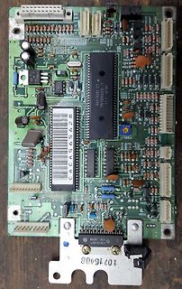
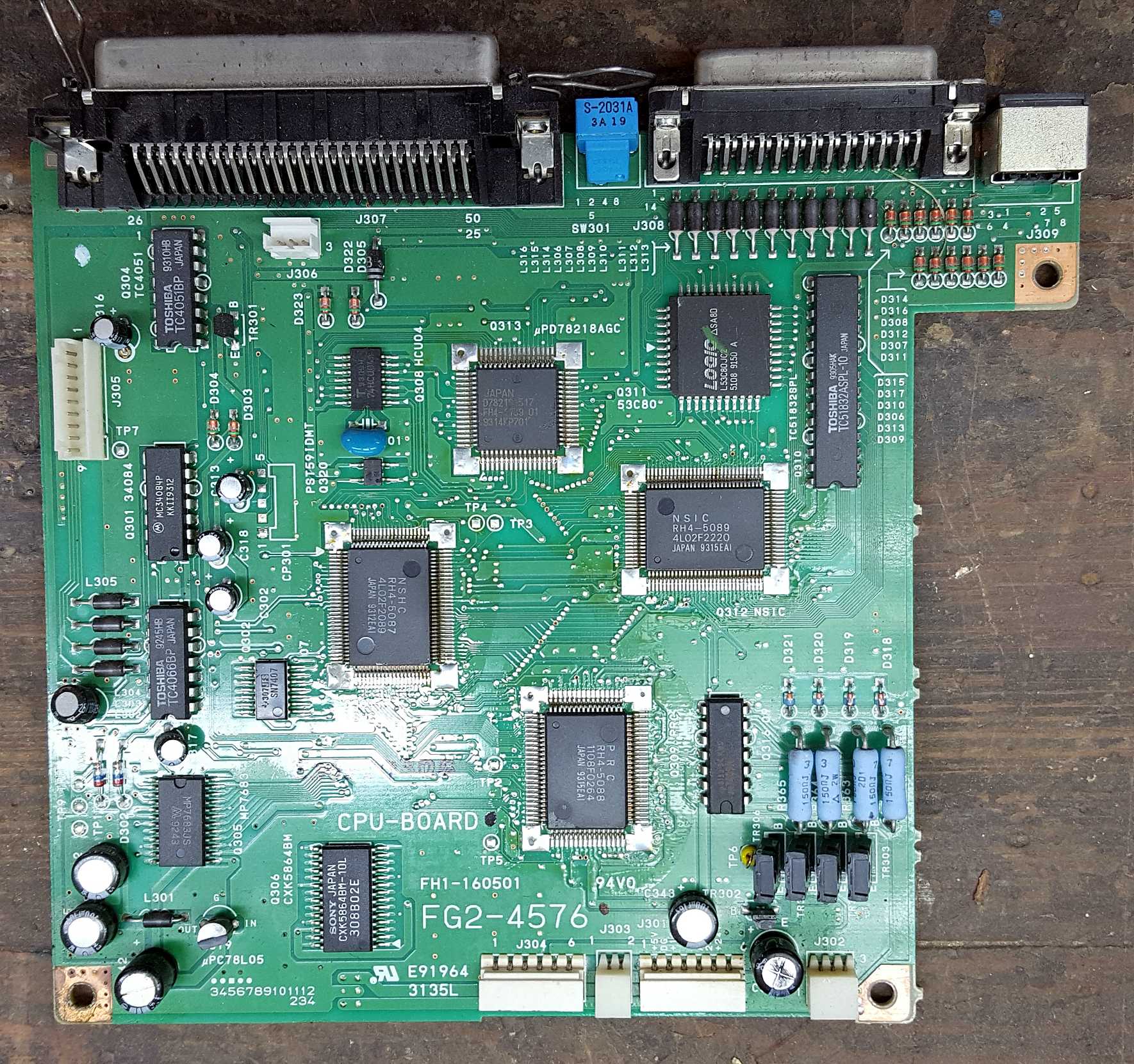
Leiterplatte mit verschiedenen integrierten Schaltkreisen und Bauteilen
JAPAN, LOGO, FG2-4576, CPU-BOARD, TOSHIBA JAPAN, TOSHIBA JAPAN, J305, J306, J307, J308, J309, J310, J312, J314, J316, J319, J320, J321, J322, J323, J324, J325, J326, J327, J328, J329, J330, J331, J332, J333, J334, J335, J336, J337, J338, J339, J340, J341, J342, J343, J344, J345, J346, J347, J348, J349,
-
 Bild
Bild
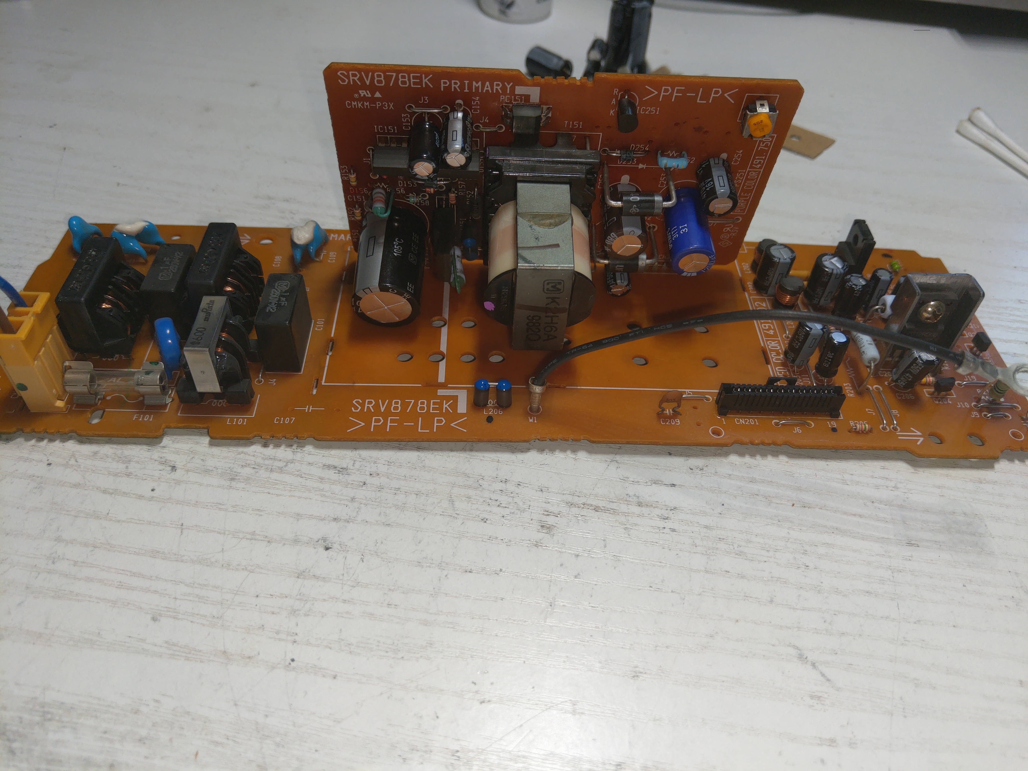
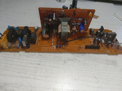
Leiterplatte eines Netzteils SRV878EK PRIMARY
C292 C293 C294 C295 C296 C297 C298 C299 C300 C301 C302 C303 C304 C305 C306 C307 C308 C309 C310 C311 C312 C313 C314 C315 C316 C317 C318 C319 C320 C321 C322 C323 C324 C325 C326 C327 C328 C329 C330 C331 C332 C333 C334 C335 C336 C337 C338
-
 Bild
Bild
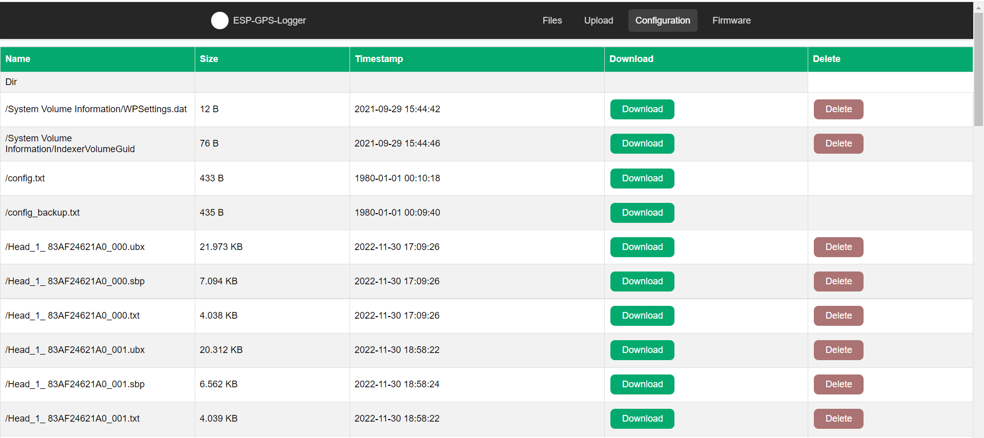
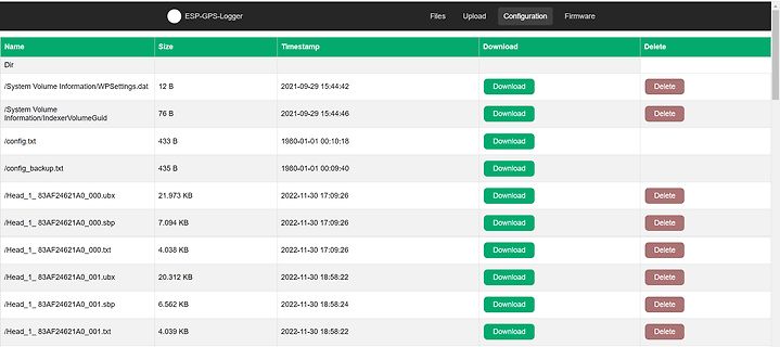
Dateiliste eines ESP-GPS-Loggers
_1_83AF24621A0_000.txt 4.038 KB 2022-11-30 17:09:26 Download Delete /Head_1_83AF24621A0_001.ubx 20.312 KB 2022-11-30 18:58:22 Download Delete /Head_1_83AF24621A0_001.sbp 6.562 KB 2022-11-30 18:58:22 Download Delete /Head_1_83AF24621A0_001.txt 4.039 KB 2022-11-30 18:58:22 Download Delete
-
 Bild
Bild
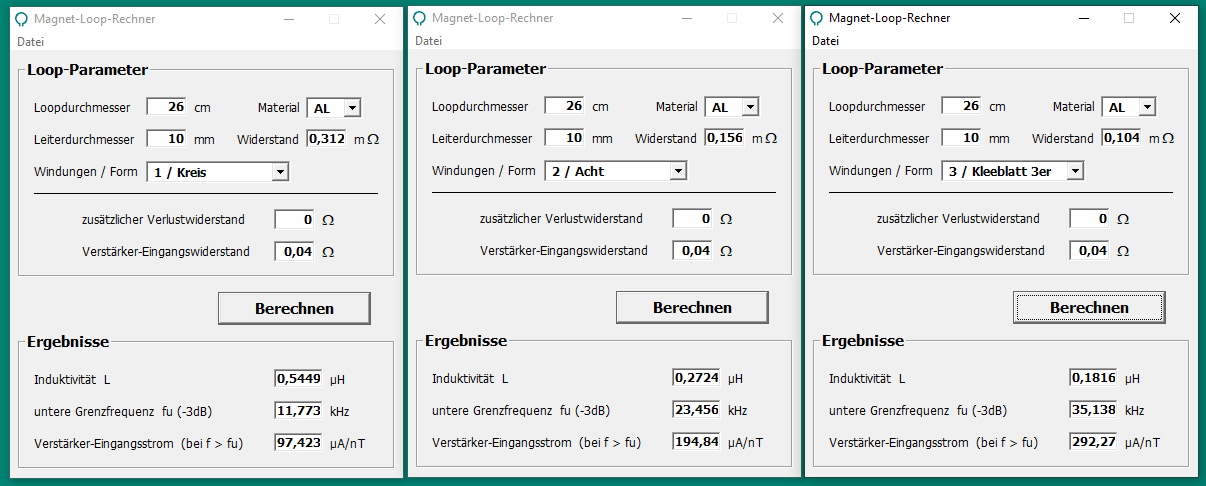
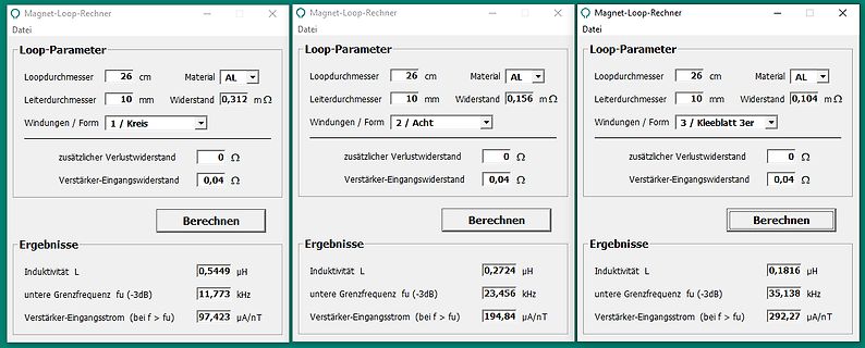
Drei Fenster eines Magnet-Loop-Rechners
Magnet-Loop-Rechner Datei Loop-Parameter Loopdurchmesser 26 cm Material AL Leiterdurchmesser 10 mm Widerstand 0,312 mΩ Windungen / Form 1 / Kreis zusätzlicher Verlustwiderstand 0 Ω Verstärker-Eingangswiderstand 0,04 Ω Berechnen Ergebnisse Induktivität L 0,5449 µH untere Grenzfrequenz fu (-3dB) 11,773 kHz Verstärker-Eingangsstrom
-
 Bild
Bild
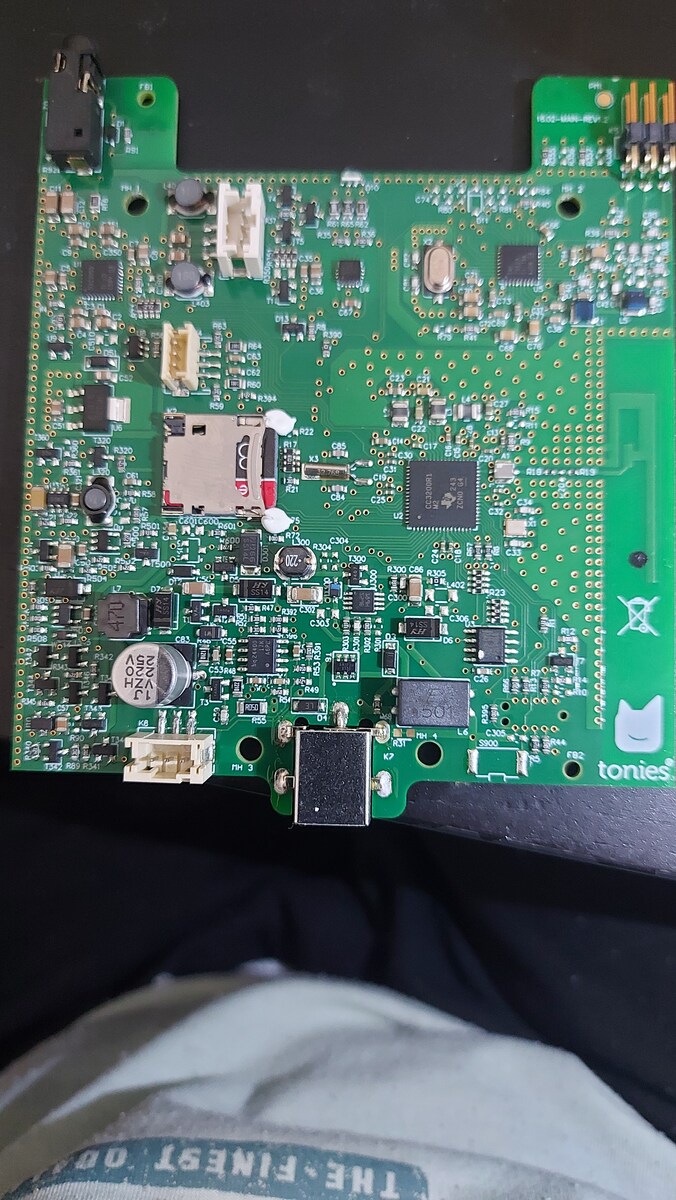
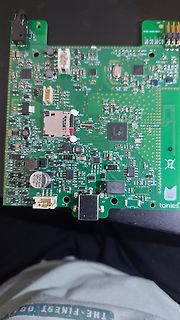
Grüne Leiterplatte mit elektronischen Bauteilen
tonies, VZH, 470, R300, C300, R301, R302, R303, R304, R305, R306, R307, R308, R309, R310, R311, R312, R313, R314, R315, R316, R317, R318, R319, R320, R321, R322, R323, R324, R325, R326, R327, R328, R329, R330, R331, R332, R333, R334, R335, R336, R337, R338, R339, R340, R341, R342, R343, R344, R345,
-
 Bild
Bild
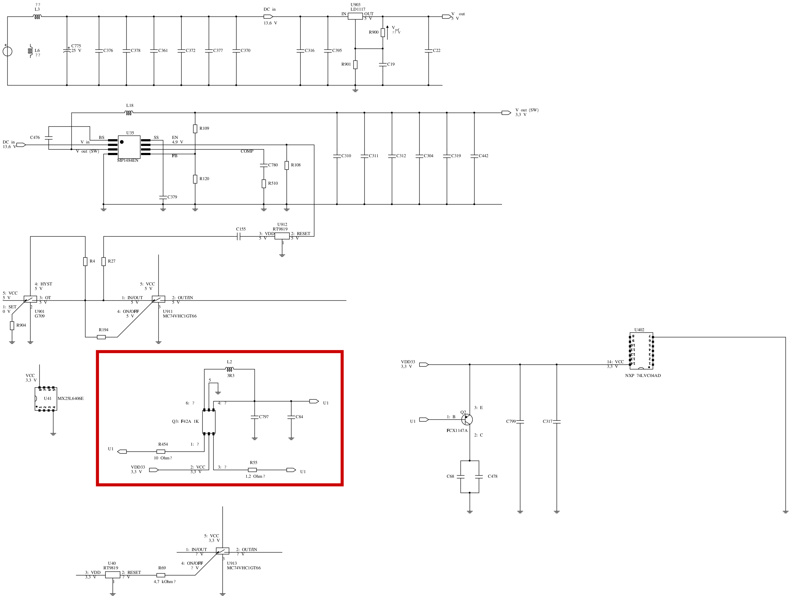
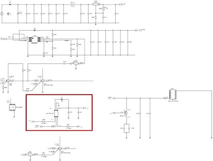
Elektronischer Schaltplan mit Spannungsreglern und Mikrocontroller
C372 C377 C316 C395 DC in 13.6V V out R985 LD1117 3.3V V out (SW) U15 SS EN 3.3V 0.8V R109 C110 C311 C312 C306 C319 C462 R320 C379 R510 R512 U3912 RESET 3.3V R4 R27 C125 U301 MC7VHCLGT66 3.3V 1. INPUT 2. OUTBN 3. VCC 4. ON/OFF 5. SET 6. HYST U901 G709 R99 R964 U1 3.3V 1. OUT 2. VCC 3. 7 10 Ohm 4. 1. 2.
-
 Bild
Bild
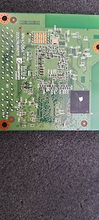
Grüne Leiterplatte mit elektronischen Bauteilen
C332 C331 C330 C329 C328 C327 C326 C325 C324 C323 C322 C321 C320 C319 C318 C317 C316 C315 C314 C313 C312 C311 C310 C309 R209 R210 R211 R212 R213 R214 R215 R216 R217 R218 R219 R220 R221 R222 R223 R224 R225 R226 R227 R228 R229 R230 R231 R232 R233 R234 R235 R236 R237 R238 R239 R240 R241 R242 R243 R244\
-
 Bild
Bild
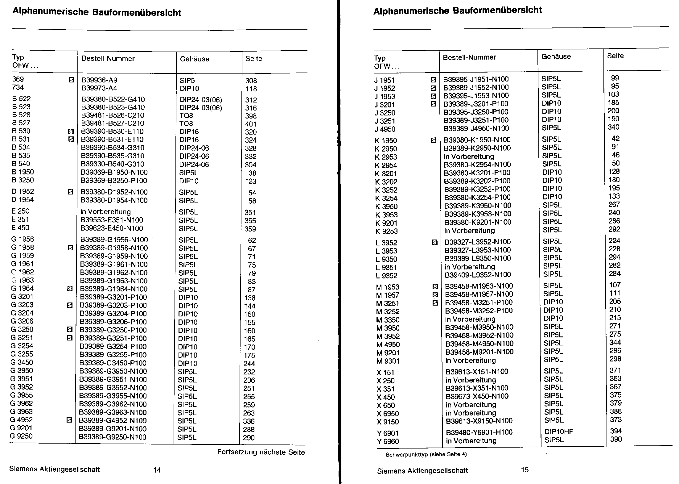
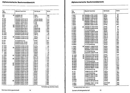
Alphanumerische Bauteilliste
Bestell-Nummer Gehäuse Seite OFW 369 B39936-A9 SIP5 308 734 B39973-A4 DIP10 118 B 522 B39380-B522 DIP24 03(06) 312 B 523 B39383-B523 DIP24 03(06) 316 B 527 B39481-B527 TO8 398 B 350 B39300-B530 DIP16 320 B 534 B39351-B531 DIP16 324 B 535 B39350-B535 DIP26 328 B 350 B39369-B350 DIP26 344 B 350 B39369-B350 SIP48 38
-
 Bild
Bild
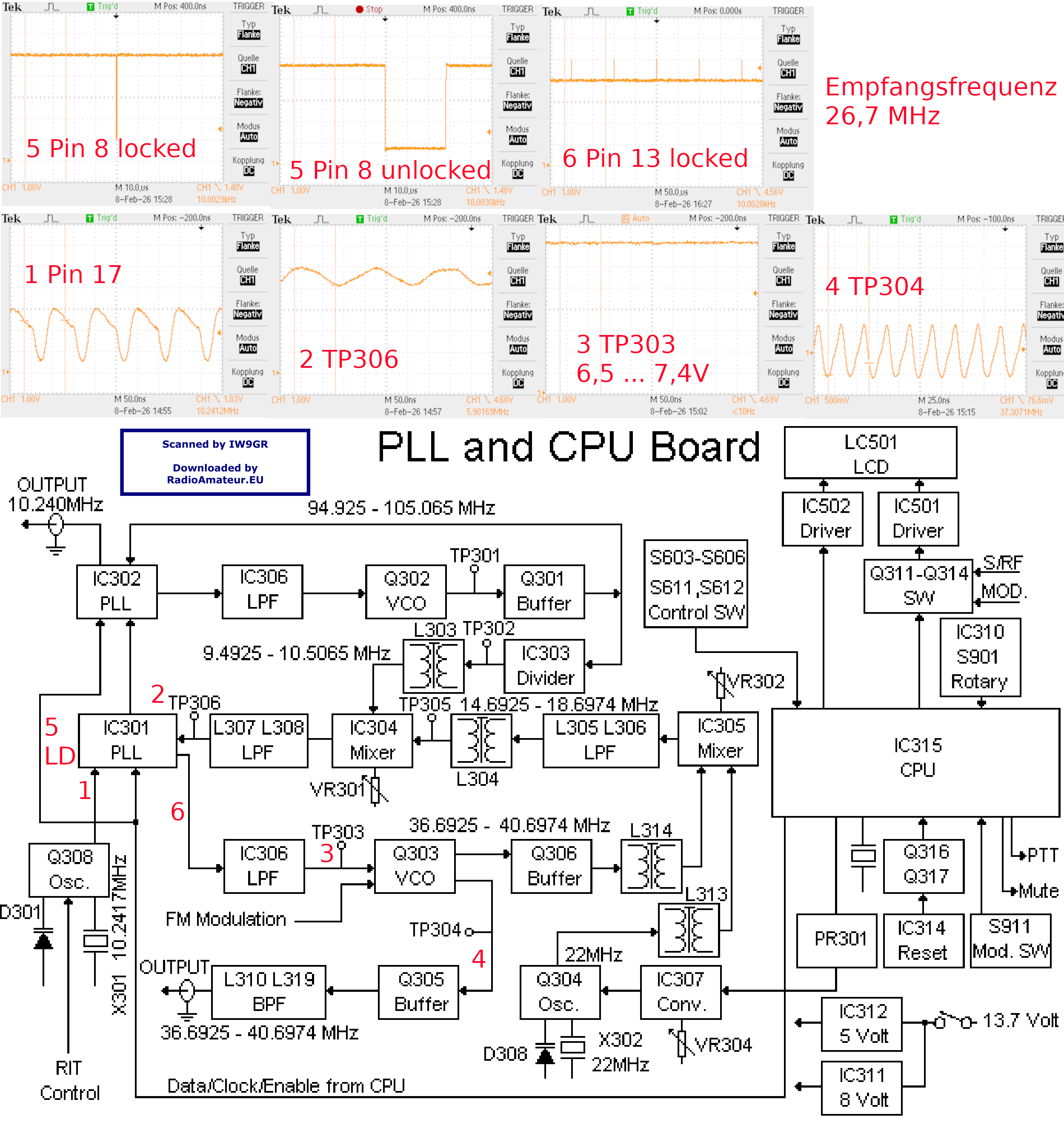
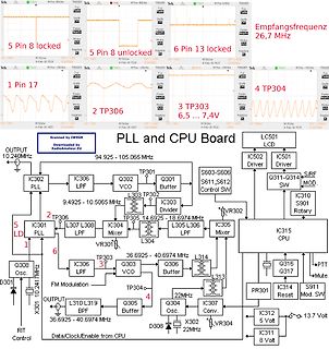
Schaltplan und Oszilloskop-Messungen einer PLL-CPU-Platine
., Q304 Osc., X302 22MHz, D308, X301, 10,2410MHz, OUTPUT, L310 BPF, 36,6925 - 40,6974 MHz, L319, IC312 5 Volt, 13,7 Volt, IC311 8 Volt, PR301 Reset, Q316 PTT, Q317 Mute, S911 Mod. SW, RIT Control, Data/Clock/Enable from CPU
-
 Bild
Bild
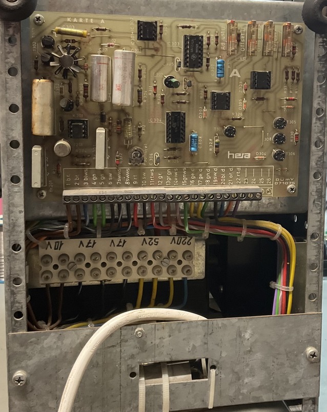
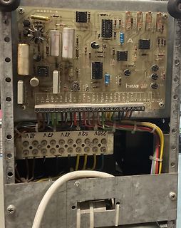
Bestückte Leiterplatte mit Anschlussklemmen
KARTE A, IC303, IC304, IC305, IC306, IC307, IC308, IC309, IC310, IC311, IC312, IC313, IC314, IC315, IC316, IC317, IC318, IC319, IC320, IC321, IC322, IC323, IC324, IC325, IC326, IC327, IC328, IC329, IC330, IC331, IC332, IC333, IC334, IC335, IC336, IC337, IC338, IC339, IC340, IC341
-
 Bild
Bild
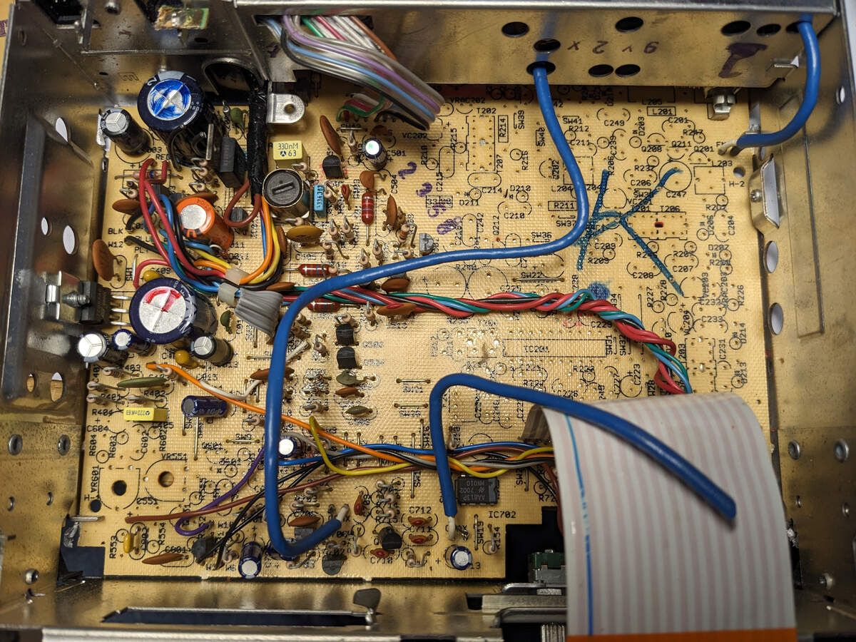
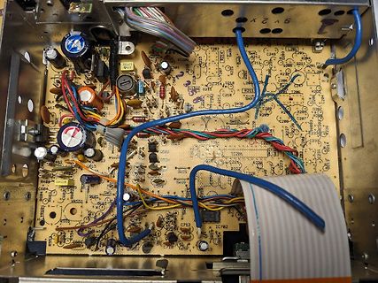
Innenansicht einer bestückten Leiterplatte in einem Gehäuse
, C296, C297, C298, C299, C300, C301, C302, C303, C304, C305, C306, C307, C308, C309, C310, C311, C312, C313,
-
 Bild
Bild
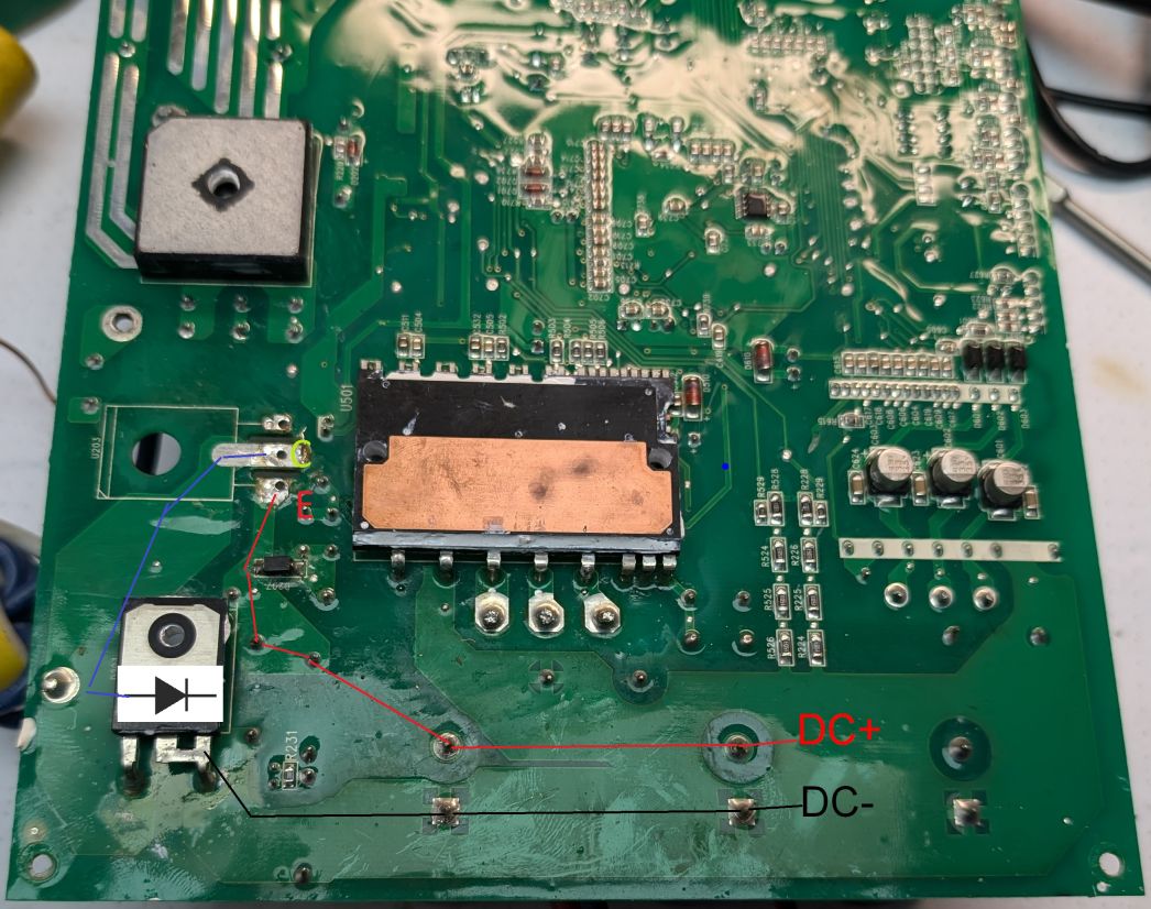
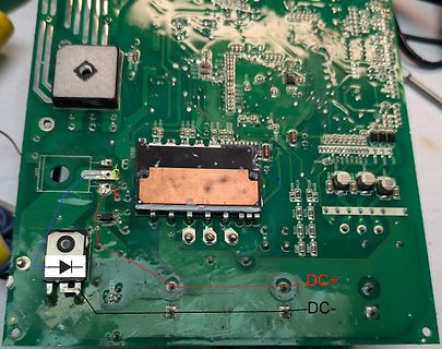
Grüne Leiterplatte mit Markierungen für DC+ und DC-
, R296, R297, R298, R299, R300, R301, R302, R303, R304, R305, R306, R307, R308, R309, R310, R311, R312, R313, R314, R315, R316, R317, R318, R319, R320, R321, R322, R323, R324, R325, R326, R327, R328, R329, R330, R331, R332, R333, R334, R335, R336, R337, R338, R33
-
 Bild
Bild
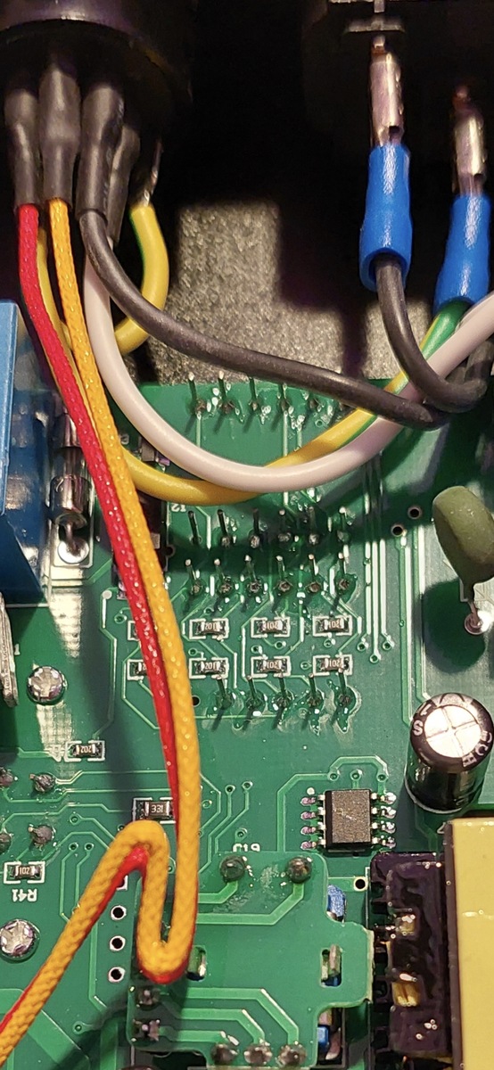
Nahaufnahme einer Leiterplatte mit Kabeln und Bauteilen
, R296, R297, R298, R299, R300, R301, R302, R303, R304, R305, R306, R307, R308, R309, R310, R311, R312, R31
-
 Bild
Bild
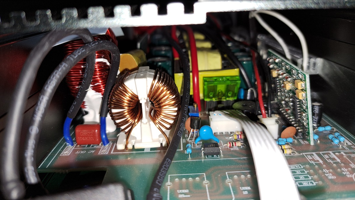
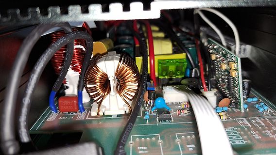
Innenansicht eines Netzteils mit Spulen und Leiterplatte
AC OUT, 0522, 104630, E23550, U322, U321, U320, U319, U318, U317, U316, U315, U314, U313, U312, U311, U310, U309, U308, U307, U306, U305, U304, U303, U302, U301, U300, U299, U298, U297, U296, U295, U294, U293, U292, U291, U290, U289, U288, U287, U286, U285, U284, U283, U282, U281, U280, U279,
-
 Bild
Bild
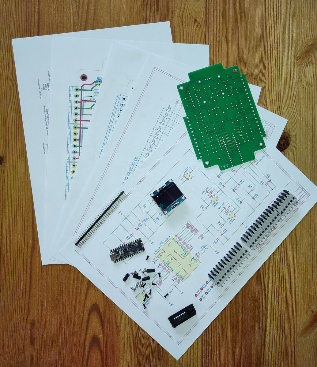
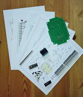
Schaltplan, Leiterplatte und elektronische Bauteile auf Holzuntergrund
, C296, C297, C298, C299, C300, C301, C302, C303, C304, C305, C306, C307, C308, C309, C310, C311, C312, C313, C314, C315, C316, C317, C318, C319, C320, C321, C322, C323, C324, C325, C326, C327, C328, C329, C330, C331, C332, C333, C334, C335, C336, C337, C338, C339, C340, C341, C342, C343, C344, C345,
-
 Bild
Bild
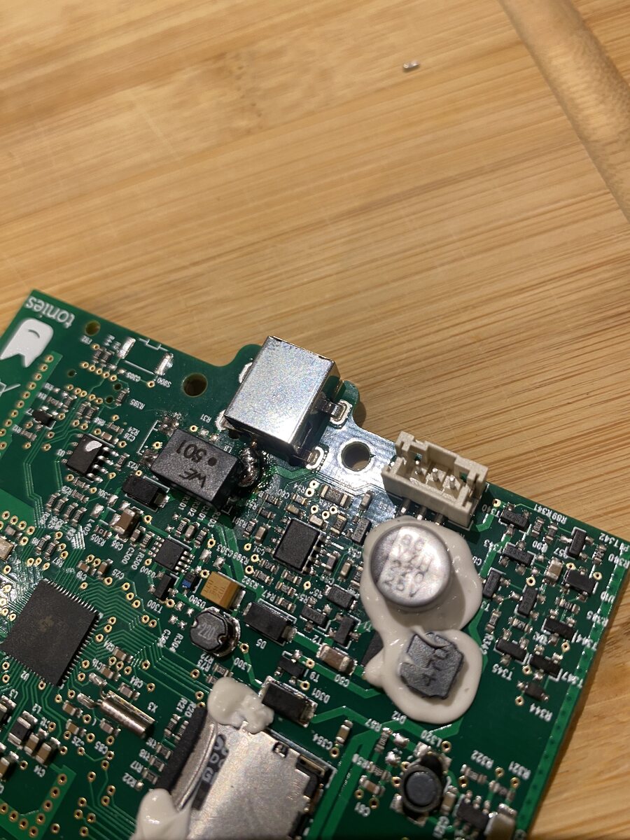
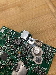
Nahaufnahme einer Leiterplatte mit Bauteilen und Kleberresten
tonies, R385, R386, C305, C306, C307, C308, C309, C310, C311, C312, C313, C314, C315, C316, C317, C318, C319, C320, C321, C322, C323, C324, C325, C326, C327, C328, C329, C330, C331, C332, C333, C334, C335, C336, C337, C338, C339, C340, C341, C342, C343, C344, C345,
-
 Bild
Bild
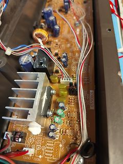
Nahaufnahme einer Leiterplatte mit Bauteilen
, R296, R297, R298, R299, R300, R301, R302, R303, R304, R305, R306, R307, R308, R309, R310, R311, R312, R313, R314, R315, R316, R317, R318, R319, R320, R321, R322
-
 Bild
Bild
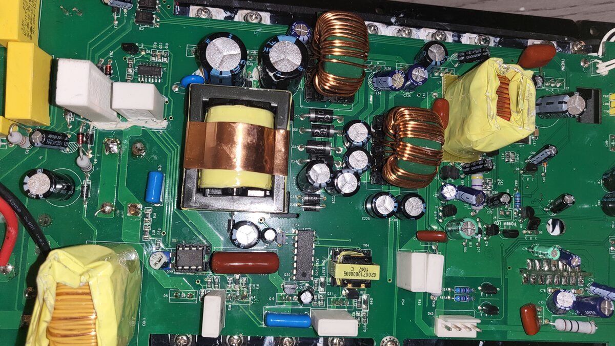
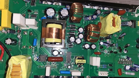
Foto einer bestückten Leiterplatte mit Netzteilschaltung
, C296, C297, C298, C299, C300, C301, C302, C303, C304, C305, C306, C307, C308, C309, C310, C311, C312, C313, C314, C315, C316, C317, C318, C319, C320, C321, C322, C323, C324, C325, C326, C327, C328, C329, C330, C331, C332, C333, C334, C335, C336, C337, C33
-
 Bild
Bild
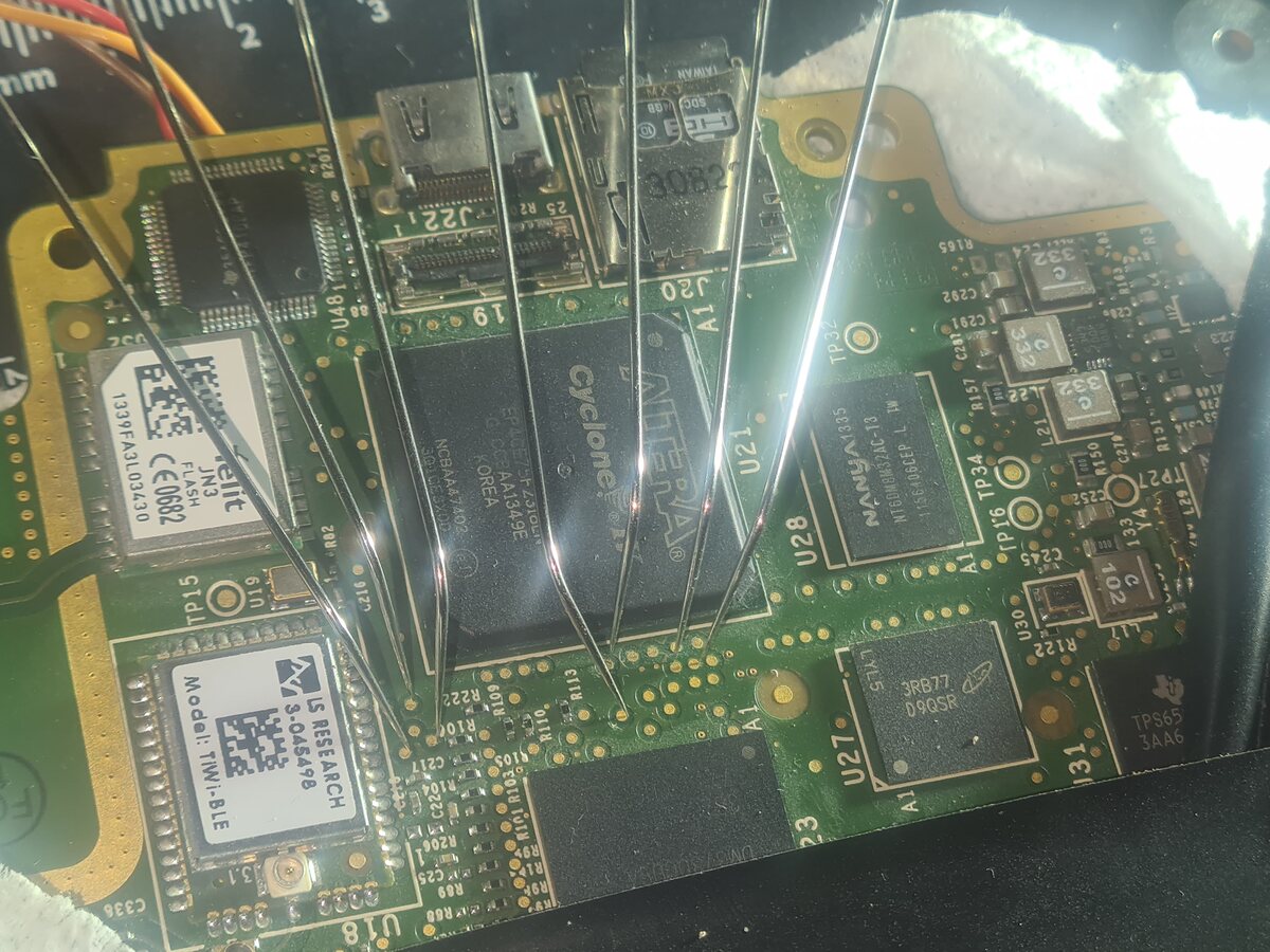
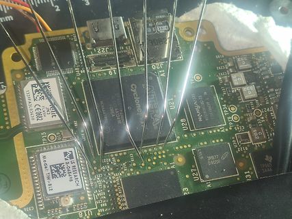
Nahaufnahme einer Leiterplatte mit FPGA und Speicherbausteinen
, C296, C297, C298, C299, C300, C301, C302, C303, C304, C305, C306, C307, C308, C309, C310, C311, C312, C313, C314, C315, C316, C317, C318, C319, C320, C321, C322, C323, C324, C325, C326, C327, C328, C329, C
-
 Bild
Bild
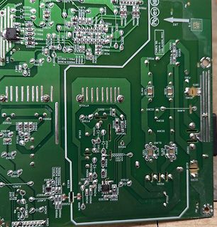
Nahaufnahme einer grünen Leiterplatte mit Bauteilbeschriftungen
AJ807, AJ808, AJ809, EL301, EL302, EL303, EL304, EL305, EL306, EL307, EL308, EL309, EL310, EL311, EL312, EL313, EL314, EL315, EL316, EL317, EL318, EL319, EL320, EL321, EL322, EL323, EL324, EL325, EL326, EL327, EL328, EL329, EL330, EL331, EL332, EL333, EL334, EL335, EL336, EL337, EL338, EL339, EL340, EL341
-
 Bild
Bild
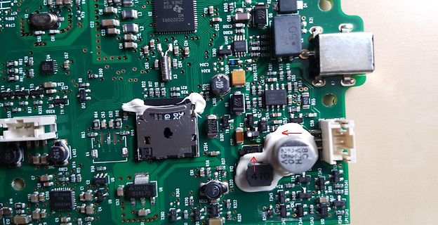
Detailaufnahme einer bestückten Leiterplatte
ZNE6 G4, MC3200R1, C25, C300, L301, 501, R304, R305, R306, R307, R310, R312, R317, R321, R322, R331, R341, R350, R352, R353, R354, R355, R356, R360, R361, R362, R363, R364, R365, R366, R371, R372, R373, R374, R375, R376, R377, R378, R379, R380, R381, R382, R383, R384, R385,
-
 Bild
Bild
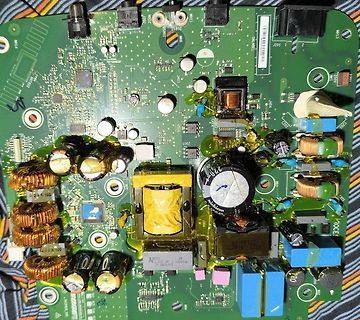
Foto einer bestückten Leiterplatte eines Netzteils
, C296, C297, C298, C299, C300, C301, C302, C303, C304, C305, C306, C307, C308, C309, C310, C311, C312, C313, C314, C315, C316, C317, C318, C319, C320, C321, C322, C3
-
 Bild
Bild
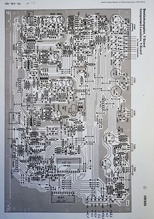
Bestückungsplan Y-Board
, C296, C297, C298, C299, C300, C301, C302, C303, C304, C305, C306, C307, C308, C309, C310, C311, C312, C313
-
 Bild
Bild
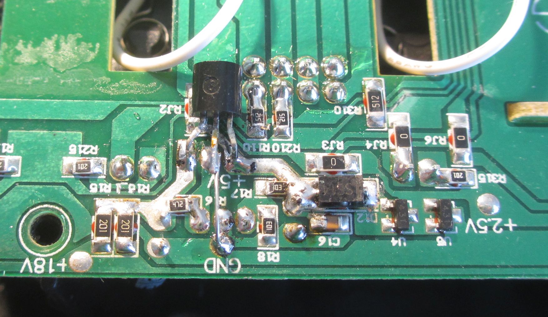
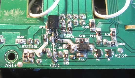
Nahaufnahme einer Leiterplatte mit Bauteilen und Lötstellen
R2, RJ2, R215, R216, R1, R15, R18, R17, R6, GND, +18V, +5V, R310, R315, R311, R312, R313, R314, R315, R316, R317, R318, R319, R320, R321, R322, R323, R324, R325, R326, R327, R328, R329, R330, R331, R332, R333, R334, R335, R336, R337, R338, R339, R340, R341, R342, R343, R344, R345,
-
 Bild
Bild
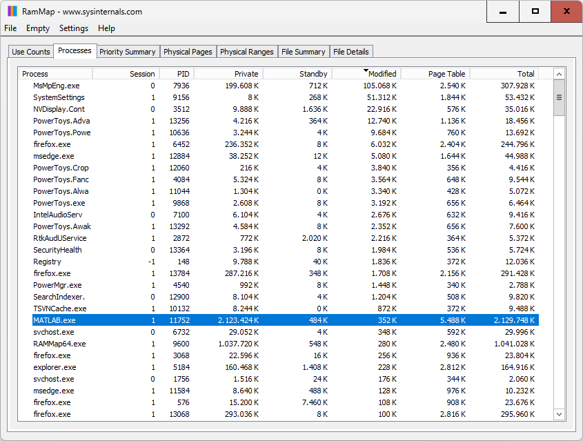
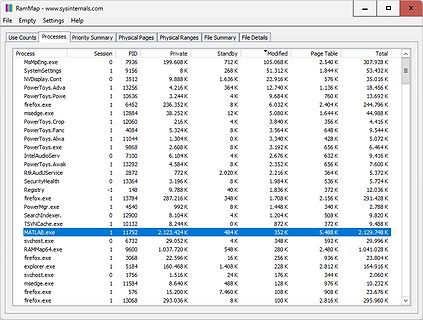
Screenshot des Windows-Tools RamMap
MsMpEng.exe 1 7936 199.608 K 712 K 105.608 K 2.540 K 307.928 K SystemSettings 1 9156 8 K 268 K 51.312 K 1.844 K 53.432 K NVDisplay.Cont 1 3512 9.888 K 1.636 K 22.916 K 576 K 35.016 K PowerToys.Adva 1 13256 4.216 K 364 K 12.740 K 1.136 K 18.456 K PowerToys.Powe 1 10636 3.244 K 4 K 9.684 K 760 K 13.692
-
 Bild
Bild
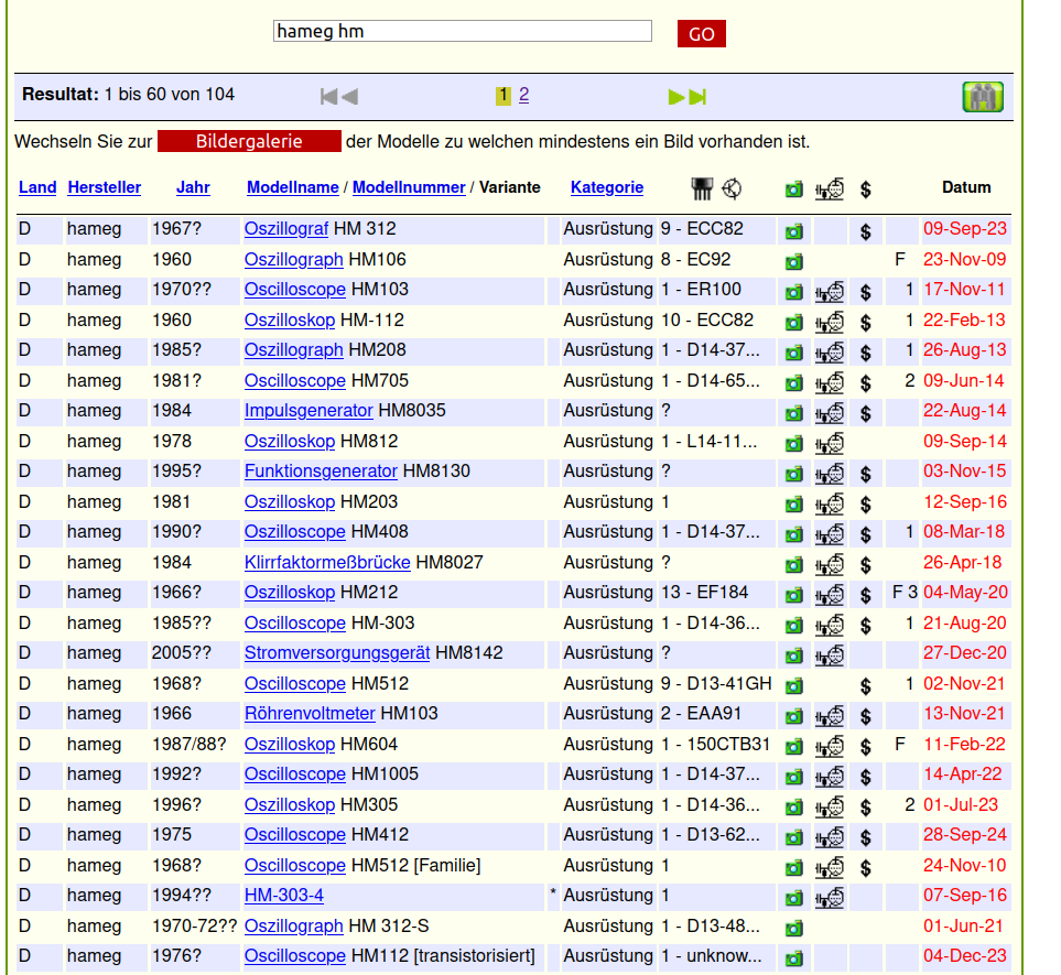
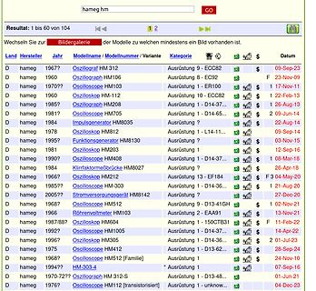
Suchergebnisliste für Hameg Geräte in einer Datenbank
Land Hersteller Jahr Modellname / Modellnummer Variante Kategorie Datum D hameg 1967? Oszillograf HM 312 Ausrüstung 9 - ECC82 $ 09-Sep-23 D hameg 1960 Oszillograph HM106 Ausrüstung 8 - EC92 F 23-Nov-09 D hameg 1970?? Oszilloscope HM103 Ausrüstung 1 - ER100 1 17-Nov-11 D hameg 1960 Oszilloskop HM-112 Ausrüstung
-
 Bild
Bild
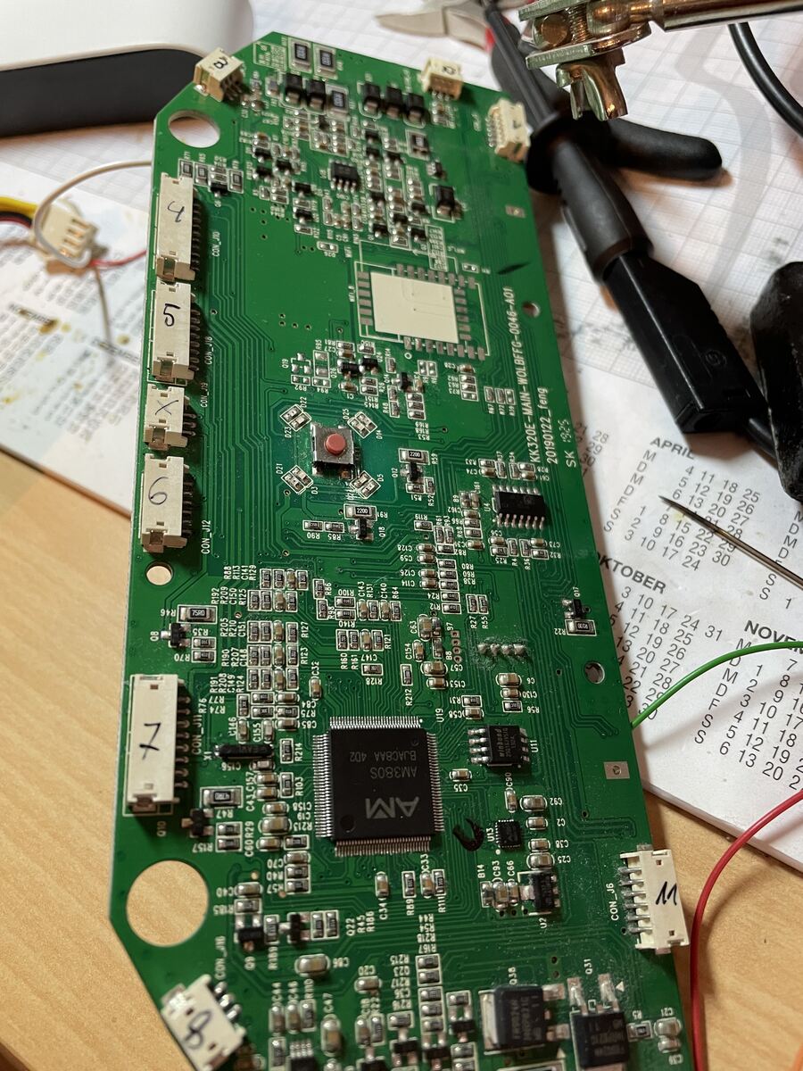
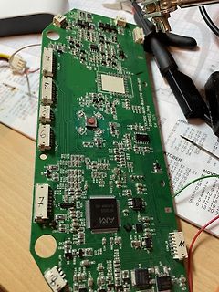
Grüne Leiterplatte mit elektronischen Bauteilen
, R296, R297, R298, R299, R300, R301, R302, R303, R304, R305, R306, R307, R308, R309, R310, R311, R312, R313, R314, R315, R316, R317, R318, R319, R320, R321, R322, R323, R324, R325, R326, R327, R328, R329, R330, R331, R332, R333, R334, R335, R336, R337, R338, R339, R340, R341, R342, R343, R344, R345,
-
 Bild
Bild
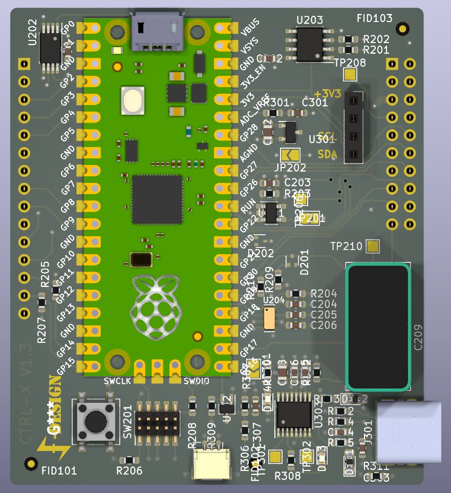
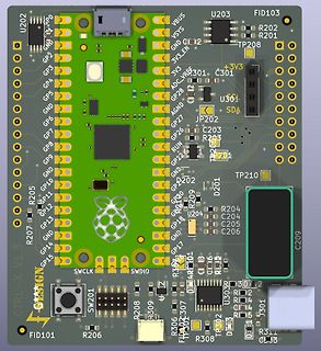
CAD-Ansicht eines Leiterplatten-Layouts
C103, C105, C104, R306, R308, SWCLK, SWDIO, R309, R305, R304, U302, R303, R302, R301, R311, R310, R312, R313, R314, R315, R316, R317, R318, R319, R320, R321, R322, R323, R324, R325, R326, R327, R328, R329, R330, R331, R332, R333, R334, R335, R336, R337, R338, R339, R340, R341, R342, R343, R344, R345,
-
Thread
Schreiben oder Lesen eines I2C-EEPROMS funktioniert nicht
144 400 22 255 5887 11 0 210 210 1 162 418 22 193 5825 17 0 206 206 1 56 312 22 199 5831 23 0 174 174 1 69 325 22 186 5818 29 0 56 56 1 81 337 22 186 5818 35 0 217 217 1 87 343 22 186 5818 41 0 53 53 1 100 356 22 243 5875 47 0 221
-
 Bild
Bild
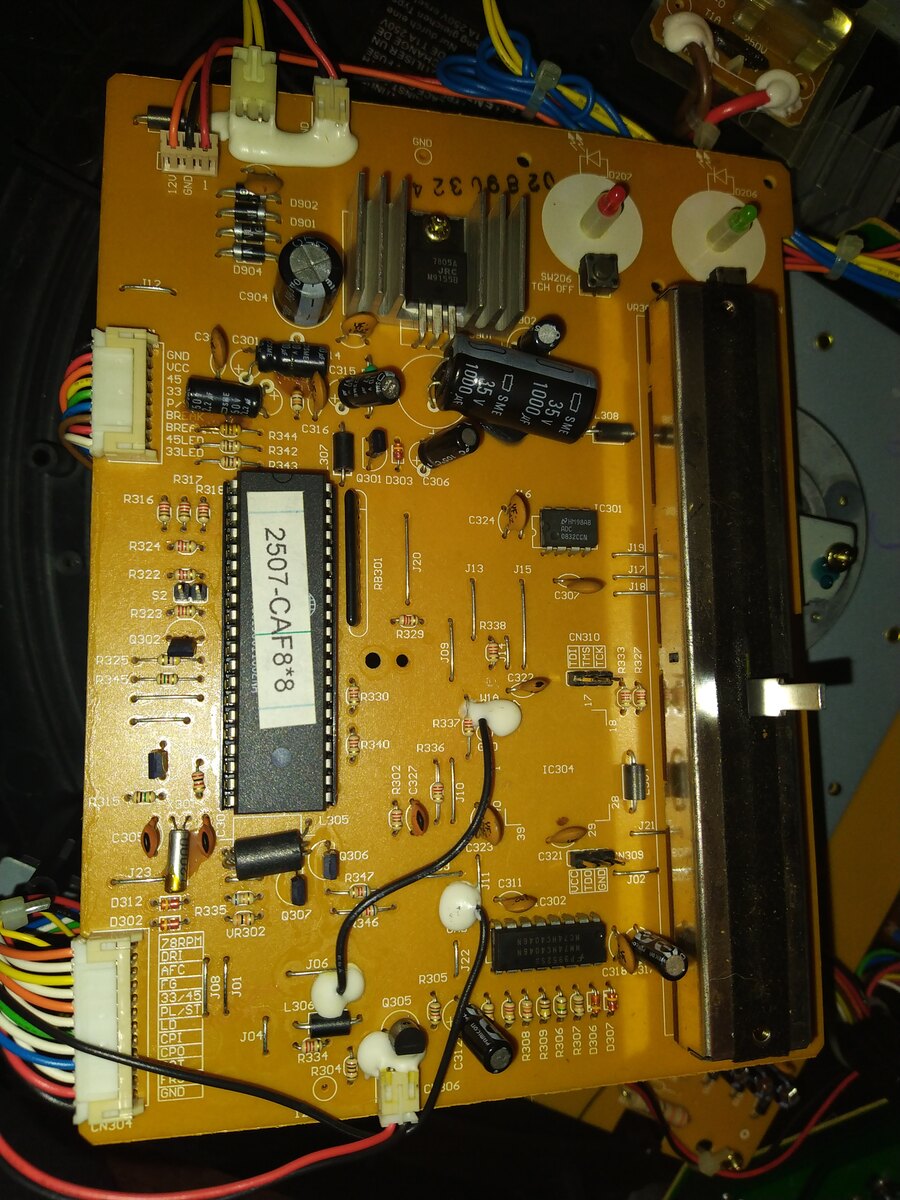
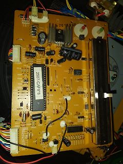
Foto einer bestückten Leiterplatte
2507-CAF8, D092, D091, D094, C904, C3, C315, C308, R344, R342, R312, R316, R324, R322, R323, R325, R345, R330, R338, R329, R336, R340, C327, C321, C311, C302, C301, J15, J13, J20, R337, R335, R334, R307, R306, R305, R304, R302, R301, C306, C304, C30, C31, C32, C33,
-
 Bild
Bild
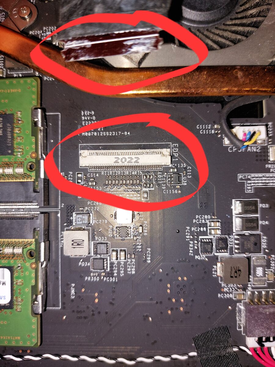
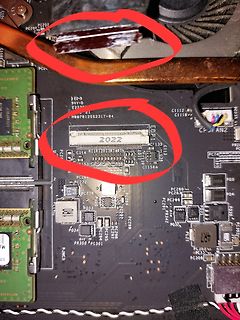
Nahaufnahme einer Leiterplatte mit roten Markierungen
PC286 PC272 PC279 PC33 PC34 PC350 PC301 PC302 PC303 PC304 PC305 PC306 PC307 PC308 PC309 PC310 PC311 PC312 PC313 PC314 PC315 PC316 PC317 PC318 PC319 PC320 PC321 PC322 PC323 PC324 PC325 PC326 PC327 PC328 PC329 PC330 PC331 PC332 PC333 PC334 PC335 PC336 PC337 PC338 PC339 PC340 PC341 PC342 PC343 PC344 PC345
-
 Bild
Bild
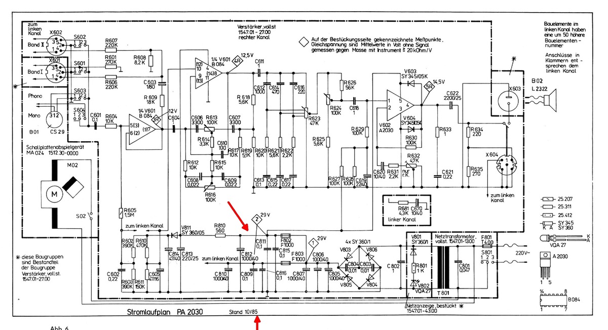
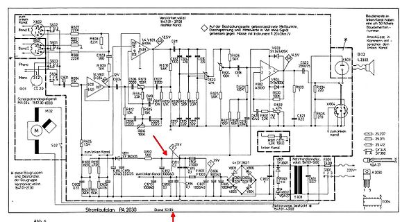
Schaltplan eines Verstärkers PA 2030
X602 S602 Band I R607 220K X601 S601 Band I R608 8,2K Phono S603 R601 220K R603 220K Mono 312 12V B04 V601 14,5V C622 2200/25 X603 L2322 B02 C604 3300 R614 330K C610 10n R617 5,6K R619 2,2K R620 5,6K R621 2,2K R622 47K R623 100K R624 100K R625 56K R626 47K R627 100K R628 2,2K R629 100K R630
-
 Bild
Bild
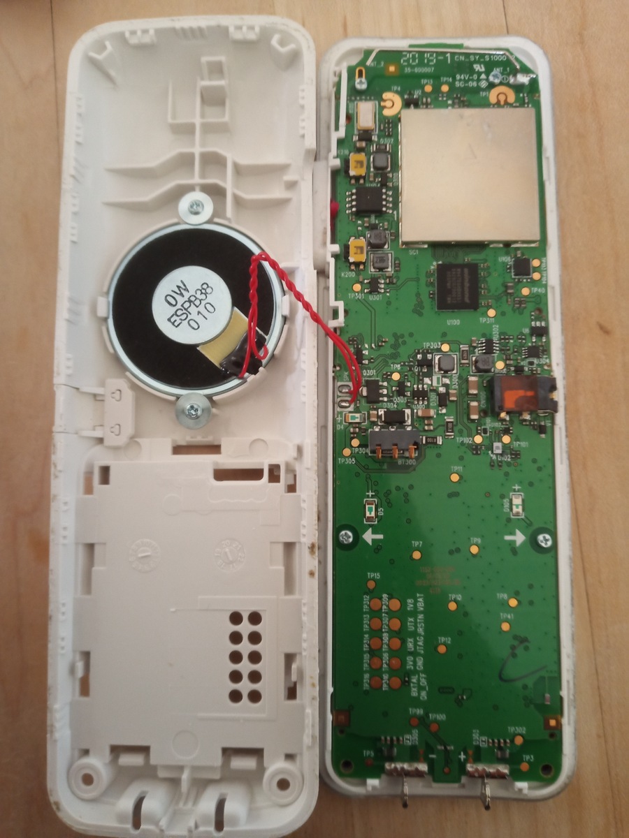
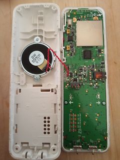
Geöffnetes elektronisches Gerät mit Lautsprecher und Leiterplatte
010 20 12-1 EN SY-S1000 94V-0 R200 TP341 U100 TP350 U100 TP355 BT300 TP2 TP15 TP308 TP309 TP310 TP312 TP313 TP314 TP315 TP316 TP317 TP318 TP319 TP320 TP321 TP322 TP323 TP324 TP325 TP326 TP327 TP328 TP329 TP330 TP331 TP332 TP333 TP334 TP335 TP336 TP337 TP338 TP339 TP340 TP341 TP342 TP343 TP344 TP345
-
 Bild
Bild
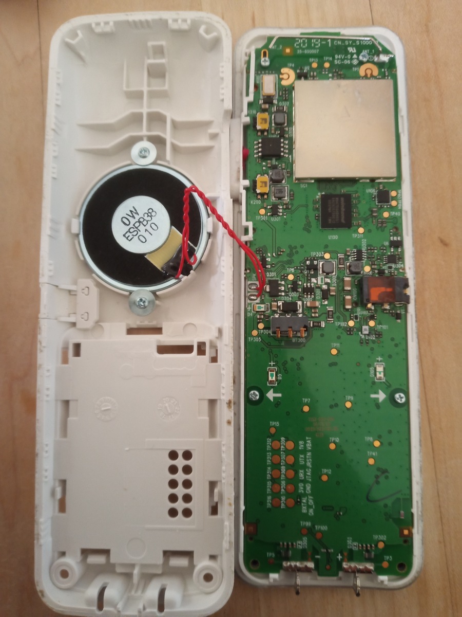
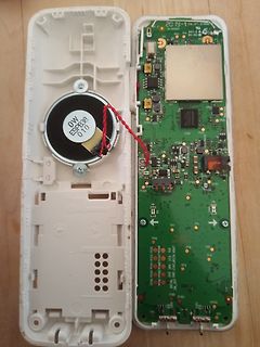
Geöffnetes elektronisches Gerät mit Lautsprecher und Leiterplatte
010 20 12-1 EN SY-S1000 94V-0 R200 TP341 U100 TP350 U100 TP355 BT300 TP2 TP15 TP308 TP309 TP310 TP312 TP313 TP314 TP315 TP316 TP317 TP318 TP319 TP320 TP321 TP322 TP323 TP324 TP325 TP326 TP327 TP328 TP329 TP330 TP331 TP332 TP333 TP334 TP335 TP336 TP337 TP338 TP339 TP340 TP341 TP342 TP343 TP344 TP345
-
 Bild
Bild
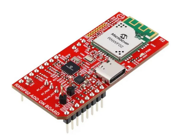
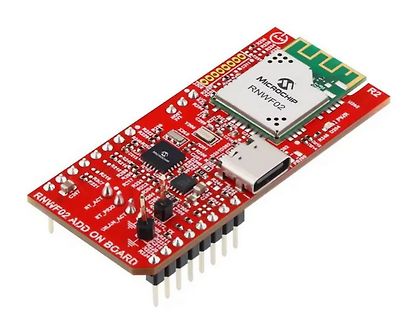
Microchip RNWF02 Add-on Board
R292 R293 R294 R295 R296 R297 R298 R299 R300 R301 R302 R303 R304 R305 R306 R307 R308 R309 R310 R311 R312 R313 R314 R315 R316 R317 R318 R319 R320 R321 R322 R323 R324 R325 R326 R327 R328 R329 R330 R331 R332 R333 R334 R335 R336 R337 R338 R339 R340 R341 R342 R343 R344 R345 R346 R347 R348 R349 R350 R351 R352
-
 Bild
Bild
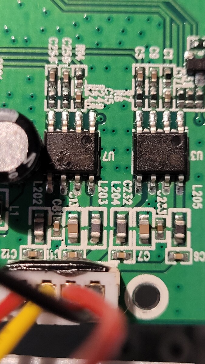
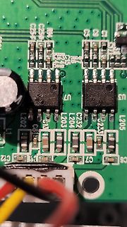
Nahaufnahme einer bestückten Leiterplatte
C292 C293 C294 C295 C296 C297 C298 C299 C300 C301 C302 C303 C304 C305 C306 C307 C308 C309 C310 C311 C312 C313 C314 C315 C316 C317 C318 C319 C320 C321 C322 C323 C324 C325 C326 C327 C328 C329 C330 C331 C332 C333 C334 C335 C336 C337 C338 C339 C340 C341 C342 C343 C344 C345 C346 C347 C348 C349 C350 C351 C352
-
 Bild
Bild
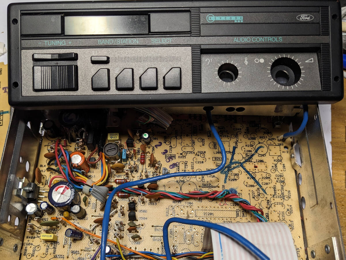
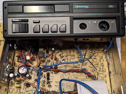
Offenes Ford Autoradio mit sichtbarer Leiterplatte
C292 C293 C294 C295 C296 C297 C298 C299 C300 C301 C302 C303 C304 C305 C306 C307 C308 C309 C310 C311 C312 C313 C314 C315 C316 C317 C318 C319 C320 C321 C322 C323 C324 C325 C326 C327 C328 C329 C330 C331 C332 C333 C334 C335 C
-
 Bild
Bild
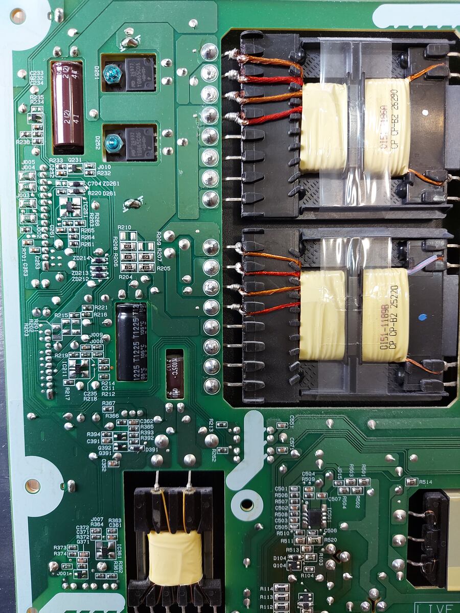
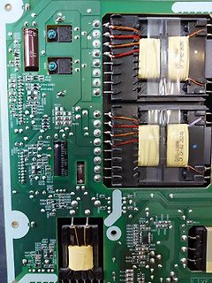
Nahaufnahme einer Leiterplatte mit Transformatoren
R292 R293 R294 R295 R296 R297 R298 R299 R300 R301 R302 R303 R304 R305 R306 R307 R308 R309 R310 R311 R312 R313 R314 R315 R316 R317 R318 R319 R320 R321 R322 R323 R324 R325 R326 R327 R328 R329 R330 R331 R332 R333 R334 R335 R336 R337 R338 R339 R340 R341 R342 R343 R344 R345 R346 R347 R348 R349 R350 R351 R352
-
 Bild
Bild
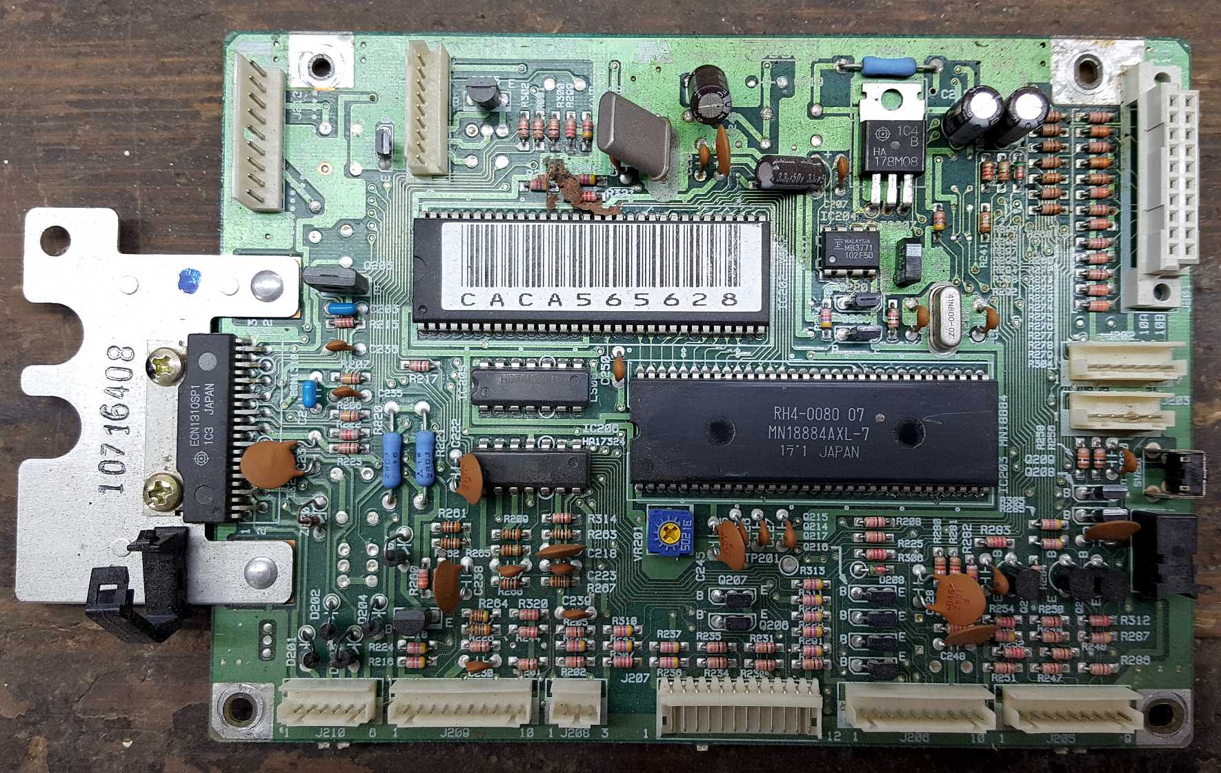
Leiterplatte mit integrierten Mikrocontrollern und elektronischen Bauteilen
R312 R287 R289 R285 R286 R284 R283 R282 R281 R280 R279 R278 R277 R276 R275 R274 R273 R272 R271 R270 R269 R268 R267 R266 R265 R264 R263 R262 R261 R260 R259 R258 R257 R256 R255 R254 R253 R252 R251 R250 R249