-
PDF
BZX79.pdf
43.90 40.0 46.0 85 375 45 150 31.4 38.8 46.6 40 0.6 47 46.10 47.90 44.0 50.0 85 375 50 170 35.0 42.9 51.8 40 0.5 51 50.00 52.00 48.0 54.0 90 400 60 180 38.6 46.9 57.2 40 0.4 5 56 54.90 57.10 52.0 60.0 100 425 70 200 42.2 52.0 63.8 40 0.3 62 60.80 63.20 58.0 66.0 120 450 80 215 58.8 64.4 71.6 35 0.3 68
in „Z Dioden mit hoher Impulsfestigkeit“ · Analoge Elektronik und Schaltungstechnik ·
-
PDF
AD811.pdf
× 45° 0.30 (0.0118) 0.30 (0.0118) 2.35 (0.0925) 0.10 (0.0039) 0.10 (0.0039) 8° COPLANARITY 1.27 0.51 (0.0201) SEATING 0° 1.27 (0.0500) 0.51 (0.0201) SEATING 8° (0.0500) 0.31 (0.0122) PLANE 0.33 (0.0130) 0.40 (0.0157) COPLANARITY PLANE 0.33 (0.0130) 0° 1.27 (0.0500) 0.10 BSC 0.20 (0.0079) 0.10 0.31 (0.0122) 0.20 (0.0079) 0.40 (0.0157) COMPLIANT TO JEDEC STANDARDS MS-013AC COMPLIANT TO JEDEC STANDARDS MS-013AA CONTROLLING DIMENSIONS ARE IN MILLIMETERS; INCH DIMENSIONS (IN PARENTHESES) ARE ROUNDED-OFF MILLIMETER EQUIVALENTS FOR CONTROLLING DIMENSIONS ARE IN MILLIMETERS
in „2 Spannungen in einer Schaltung“ · Analoge Elektronik und Schaltungstechnik ·
-
PDF
S8254A_E.pdf
CCTpincapacitance=0.1μF 0.5 1.0 1.5 s 3 Overdischargedetection delaytime tDL CDTpincapacitance=0.1μF 50 100 150 ms 3 Overcurrentdetection t CDTpincapacitance=0.1μF 5 10 15 ms 3 delaytime1 IOV1 Overcurrentdetection tIOV2 ⎯ 0.4 1 1.6 ms 3 delaytime2 Overcurrentdetection delaytime3 tIOV3 FETgatecapacitance2000pF 100
in „18650 protection charger board Frage“ · Analoge Elektronik und Schaltungstechnik ·
-
PDF
SED1565.pdf
SED1568** SED1569*** 0 1 0 1 1 0 0 0 * * * Normal COM0→COM63COM0→COM47COM0→COM31COM0→COM53COM0→COM51 1 ReverseCOM63→COM0COM47→COM0COM31→COM0COM53→COM0COM51→COM0 * Disabled bit Power Controller Set This command sets the power supply circuit functions. See the function explanation in “The Power Supply
in „Pollin 128x64 GLCD : Bild verzerrt“ · Mikrocontroller und Digitale Elektronik ·
-
PDF
MP2363_r1.3.pdf
L 2A/div. VOUT 10mV/div. V VOUT OUT 1V/div. 1V/div. VIN 200mV/div. L L 1A/div. 2A/div. V 10V/div. 4ms/div. 2ms/div. Shutdown through Enable Shutdown through Enable OUT = 1.5A Resistive Load IOUT = 3A Resistive Load V OUT VOUT 1V/div. 1V/div. IL L 1A/div. 2A/div. MP2363 Rev. 1.3 www.MonolithicPower.com
in „Schaltregler gesucht“ · Mikrocontroller und Digitale Elektronik ·
-
PDF
UBA2000.pdf
and 230 V). The current entering this pin must be limited to <10 mA. 3. Inrush current, duration <2 ms. QUALITY SPECIFICATION In accordance withNW-FQ-611-EÓ with the following exception: With respect to the integrated sense resistor a lifetime of 60000 lamp starts (with max. 7 start attempts) at maximum
in „Schnellstarter für Leuchtstofföhren - welche taugen was?“ · Haus & Smart Home ·
-
Datei
Schrittmotor.asm
MS3x ;Kein Überlauf ldi AH, 0 sts PWM5, AH sts PWM3, AL ;Übertrag com AL sts PWM4, AL ldi AL, LOW(MS4) sts PWMAdrl, AL ldi AL, HIGH(MS4) sts PWMAdrh, AL ret MS32: ;rechts rum sbc AL, AH brcc MS3x ;Kein
in „Spielerei mit einem 5-Phasen-Schrittmotor“ · Projekte & Code ·
-
Datei
nRF24L01_Tutorial_RX_-_MAIN.c
/* * nRF24L01_Tutorial_RX.c * * Created: 06.01.2012 22:51:57 * Author: Ernst Buchmann */ #ifndef F_CPU //define F_CPU if not done #define F_CPU 20000000UL #endif #include <avr/io.h> #include <avr/interrupt.h> #include <util/delay.h> #include <stdlib.h> #include
in „2,4 Ghz Kommunikation“ · Mikrocontroller und Digitale Elektronik ·
-
Datei
main_RX.c
/* * nRF24L01_Tutorial_RX.c * * Created: 06.01.2012 22:51:57 * Author: Ernst Buchmann */ #ifndef F_CPU //define F_CPU if not done #define F_CPU 16000000UL #endif #include <avr/io.h> #include <avr/interrupt.h> #include <util/delay.h> #include <stdlib.h> #include
in „Probleme mit NRF24L01 Tutorial“ · Mikrocontroller und Digitale Elektronik ·
-
PDF
lcd_datasheet.pdf
35 mV Tolerance of VCM ΔVCM - - 35 mV [Note] *1) zPower sequence(VCC turn on conditions) : t1 ≦ 10 ms 1sec ≦ t5 0.01ms < t2 ≦ 50ms 200ms≦t6 0.01ms< t3 ≦ 50ms 200ms≦t7 0.01ms< t4 ≦10 ms Vin=3.3V 3.0V 3.0V LCD Power Supply data Logic Signal 0.3V 0.3V 0.3V t1 t2 t3 t4 t5 VL Backlight Power Supply t6 t7
in „Laptop LCD inverter board frage“ · Analoge Elektronik und Schaltungstechnik ·
-
PDF
CLAA154WA05AN_ASUS_A6JC_display.pdf
35 mV Tolerance of VCM ΔVCM - - 35 mV [Note] *1) zPower sequence(VCC turn on conditions) : t1 ≦ 10 ms 1sec ≦ t5 0.01ms < t2 ≦ 50ms 200ms≦t6 0.01ms< t3 ≦ 50ms 200ms≦t7 0.01ms< t4 ≦10 ms Vin=3.3V 3.0V 3.0V LCD Power Supply data Logic Signal 0.3V 0.3V 0.3V t1 t2 t3 t4 t5 VL Backlight Power Supply t6 t7
in „Laptop LCD ansteuern wollen // FPGA einstieg ?“ · Mikrocontroller und Digitale Elektronik ·
-
Datei
enc28j60.c
CPOL)|(0<<CPHA)|(0<<SPR1)|(0<<SPR0); SPSR = (1<<SPI2X); //reset enc28j60: ENC28J60_RESET_LO(); _delay_ms(10); ENC28J60_RESET_HI(); //after reset we have to wait at least 50us ! _delay_us(60); //workaround for bad chip revisions: wait >1ms (wait 10ms...) _delay_ms(10); //wait for ready flag while((!(enc28j60
in „ENC28J60 correct value of PHLCON and mirrored registers“ · Mikrocontroller und Digitale Elektronik ·
-
PDF
CMX813.pdf
12 474.8 0 1 0 0 1 1 1 1 4F 2 2043.8 13 495.8 0 1 0 1 0 0 0 0 50 3 2094.5 14 517.8 0 1 0 1 0 0 0 1 51 4 2155.6 15 540.7 0 1 0 1 0 0 1 0 52 5 2212.2 16 564.7 0 1 0 1 0 0 1 1 53 6 2271.7 17 589.7 0 1 0 1 0 1 0 0 54 7 2334.6 18 615.8 0 1 0 1 0 1 0 1 55 8 2401 19 643 2000 Consumer Microcircuits Limited
in „leidiges Thema - SPI“ · Mikrocontroller und Digitale Elektronik ·
-
PDF
3901090614.pdf
93.75% for Data2. Note: EEPROM error signaling is implemented in automotive grade parts only. T=100ms (PWM = 10Hz) t=16.875ms Start Extended PWM mode sensor 1 t1 t2 0 1 T 8 T 15T T 16 16 16 T=100ms (PWM = 10Hz) t=73.125ms Start Extended PWM mode sensor 2 t1 t2 0 16 T 16 T t3 16T T Figure 17: Example:
in „Erste Schritte mit TWI“ · Mikrocontroller und Digitale Elektronik ·
-
Datei
lwip-1.4.0-rc2.patch
lwip_open_src_template_proj_for_v1.3.0/lwip_open_src_template_app/lwip/core/dhcp.c --- ./core/dhcp.c 2011-02-03 13:51:14.000000000 +0100 +++ ../../lwip_open_src_template_proj_for_v1.3.0/lwip_open_src_template_app/lwip/core/dhcp.c 2015-08-14 09:42:24.000000000 +0200 @@ -288,16 +288,24 @@ dhcp_option(dhcp, DHCP_OPTION_SERVER_ID
in „ESP8266 OpenSrc LWIP implementation“ · Mikrocontroller und Digitale Elektronik ·
-
PDF
HM-10_DataSheet_V550_2017-07.pdf
-29---Last Version V550 2017-07 HM Bluetooth module datasheet AT+COMI[P1] OK+Set:[P1] Default: 3(20ms) P1 Value: 0: 7.5ms; 1: 10ms; 2: 15ms; 3: 20ms; 4: 25ms; 5: 30ms; 6: 35ms; 7: 40ms; 8: 45ms; 9: 4000ms Note: This command is added since V538 16.Query/Set Maximum Link Layer connection interval Send Receive Parameter AT+COMA? OK+Get:[P1] P1: 0 ~ 9 AT+COMA[P1] OK+Set:[P1] Default: 7(40ms) P1 Value: 0: 7.5ms; 1: 10ms; 2: 15ms; 3: 20ms; 4: 25ms; 5: 30ms; 6: 35ms; 7: 40ms; 8: 45ms; 9: 4000ms Note: This command is added since V538 17.Query/Set Link Layer connection slave latency Send Receive
in „Hilfe bei BTLE iBeacon bzw. CENTRAL-Mode“ · Mikrocontroller und Digitale Elektronik ·
-
PDF
adxl380.pdf
1P8withInternalLowDropoutRegulator(LDO)Bypassed V SUPPLY=0V 1.62 1.8 1.98 V SupplyResetThreshold(V ) 1.2 V RESET HoldTime 1 ms analog.com Rev. 0 | 5 of 103 Data Sheet ADXL380 SPECIFICATIONS Table1.Specifications(Continued) TestConditions/ Parameter Comments Min Typ Max Unit RiseTime 0Vto90%ofV S 4 ms 11 SupplyCurrent LDOenabled
in „ADXL380 mit SPI auslesen“ · Mikrocontroller und Digitale Elektronik ·
-
Datei
Programm.c
UCSZ02) | (1<<UCSZ01) | (1<<UCSZ00) | (0<<UPM01) | (0<<UPM00) | (0<<USBS0); // 9600 baud rate UBRR0 = 51; // Disable watchdog wdt_disable(); // Enable interrupts sei(); PORTB &= ~(1<<LED_RED); while (1) { PORTB ^= (1 << LED_GREEN); _delay_ms(500); } } // UART receive interrupt ISR(USART_RX_vect) { if (UDR0
in „Bootloader und Watchdog Reset“ · Mikrocontroller und Digitale Elektronik ·
-
Datei
init.c
//ICC-AVR application builder : 05.01.2015 08:44:51 // Target : T2313 // Crystal: 16.000Mhz #include <iot2313v.h> #include <macros.h> void port_init(void) { PORTA = 0x00; //Unused (Reset + XTAL) DDRA = 0x00; PORTB = 0x38; //ATTN,ACK + 3 LEDs DDRB = 0x47
in „ATTiny2313 läuft nicht immer an“ · Mikrocontroller und Digitale Elektronik ·
-
Datei
test.c
********************* //* PERFORM HARDWARE RESET //* This routine toggles ATA RESET line low for 10ms. //* //****************************************************************** void ata_hard_reset(void) { avr_databus_in; PORT_ATA_IO_CNTL = ATA_IO_HIZ; PORT_ATA_IO_CNTL &= ~ATA_RESET; delay_ms(100); PORT_ATA_IO_CNTL
in „Problem mit der IDE-Festplatte“ · Mikrocontroller und Digitale Elektronik ·
-
Datei
Main.c
servo_loop < 200 ; servo_loop++) { PORTD |= 0x04; // servo signal on pin 4 PORT D2 // Delay(5); // 1.17 ms pulse - fully clockwise Delay(23); // 1.51 ms pulse - center position - latch locked // Delay(32); // 1.87 ms pulse - fully anticlockwise - release!!!! PORTD &= ~0x04; Delay(50); // 18.0 ms between servo
in „AFSK über AVR“ · Mikrocontroller und Digitale Elektronik ·
-
PDF
ad7706.pdf
the RESET input is low. When the RESET voltage levels. Typical start-up times with VDD = 5 V are 6 ms input returns high, the AD7705/AD7706 starts to process data using a 4.9512 MHz crystal, 16 ms with a 2.4576 MHz crystal and 20 ms with a 1 MHz crystal oscillator. Start-up times are and DRDY will return
in „ADC7706 - Kommunikationsproblem“ · Mikrocontroller und Digitale Elektronik ·
-
PDF
8020_8021_Users_Manual.pdf
amplitude MV, V OFS Program output offset MV, V (Model 8021 only) WID Program pulse width NS, US, MS, S (Mode 8022 only) CAR Program carrier Level % STP Program sweep stop HZ, KHZ, MHZ SWT Program sweep time NS, US, MS, S RPT Program internal trig. generator peNS, US, MS, S MRK Program sweep marker
in „Handbuch für Funktionsgenerator Kontron 8021 gesucht“ · Offtopic ·
-
PDF
OZW67_en__ProductRelease_V3.pdf
and part picture (loaded from the Cache, if already available) x Number of datapoints (several 100 ms per datapoint) x Text and Link can be ignored o Normally there is enough memory on the web server available. Otherwise a warning message appears x Any number of browsers can be used simultaneously. The
in „Brötje ISR Plus Kommunikation / LPB“ · Haus & Smart Home ·
-
PDF
SerialComInstruments_Doku.pdf
"Hallo MC" do for i =0 to 6.28 step 0.02 f = fsin(i * 3) print SendStringN(1,i); print SendStringN(51,i); print SendStringN(52,f); print SendStringN(60,i * 36 ); print SendStringS(35,s) waitms 100 next loop ' Funktion erzeugt kompletten Protokoll-String für Zahlenwerte function SendStringN(InstrNr as
in „Projekt: Virtuelle Instrumente an serielle Schnittstelle“ · Projekte & Code ·
-
PDF
ne25139.pdf
4V, G1S = 0 µA 10 |YFS| Forward Transfer Admittance at DS = 5 V, G2S = 1 V, ID= 10 mA, f = 1.0 kHz mS 18 25 35 C ISS f = 1 MHzacitance at DS = 5 V, G2S = 1 V,DI= 10 mA, pF 0.5 1.0 1.5 CRSS D Reverse Transfer Capacitance at DS = 5 V, VG2S= 1 V, ID= 10 mA, f = 1 MHz pF 0.02 0.03 California Eastern Laboratories
in „GaAs NE25139 ersetzen“ · Analoge Elektronik und Schaltungstechnik ·
-
PDF
Grundig_ST70-780_text_Service-Manual.pdf
Oscillograms Chassis 2 2 0V 0V 1 1 0V 0V 0V 0V 0V 0V 3 3 1 3 1V/cm, 5µs/cm 4 100mV/cm, 5µs/cm 5 50V/cm, 10ms/cm 1 3 1V/cm, 5µs/cm 2 5V/cm, 5µs/cm 2 5V/cm, 5µs/cm Standby 10 23 0V 8 0V 0V 22 9 0V 0V 12 7 0V 11 0V 0V 0V 7 22 23 2V/cm, 5ms/cm 8 200mV/cm, 5ms/cm 8 500mV/cm, 5ms/cm 9 5V/cm, 5ms/cm 10 20V/cm, 5ms/cm 11 5V/cm, 5ms/cm 12 10V/cm, 5ms/cm 13 15 16 16 0V 0V 0V 0V 0V 14 49 16A 16A 0V 0V 0V 13 10V/cm, 20µs/cm 14 5V/cm, 20µs/cm 16 50V/cm, 10ms/cm 16 50V/cm, 20µs/cm 49 1V/cm, 20µs/cm 15 500V/cm, 20µs/cm 16A 100V/cm, 10ms
in „PAL-Röhren TV auf NTSC umbauen“ · Analoge Elektronik und Schaltungstechnik ·
-
PDF
msp430f413.pdf
INCLK 53 - P1.0 TA0/TA0.0 CCI0A 53 - P1.0 52 - P1.1 TA0/TA0.0 CCI0B CCR0 TA0/TA0.0 DVSS GND DVCC VCC 51 - P1.2 TA1/TA0.1 CCI1A 51 - P1.2 CAOUT (internal) CCI1B CCR1 TA1/TA0.1 DVSS GND DVCC VCC 45 - P2.0 TA2/TA0.2 CCI2A 45 - P2.0 ACLK (internal) CCI2B CCR2 TA2/TA0.2 DVSS GND DVCC VCC 16 POST OFFICE BOX
in „MSP430F413 Analog eingänge“ · Mikrocontroller und Digitale Elektronik ·
-
PDF
e1529_k8v.pdf
[1.28us] [2.56us] [5.12us] [10.2us] [20.5us] [41.0us] [81.9us] [163.8us] [327.7us] [655.4us] [1.31ms] [2.62ms] [5.24ms] [10.49ms] [20.97ms] [42.00ms] [84.00ms] DataCacheBGScrub[Disabled] Disables or sets theL1datacacheRAMtobecorrectedwhenidle. Configurationoptions: [Disabled] [40ns] [80ns] [160ns] [
-
PDF
2572.pdf
V Dropout voltage I = 500 mA 1.05 1.15 V d O I = 800 mA 1.10 1.2 O Thermal regulation T = 25°C, 30ms Pulse 0.01 0.1 %/W a 14/41 LD1117xx Electrical characteristics Table 10. Electrical characteristics of LD1117#50 (refer to the test circuitJ, T = 0 to 125 °CO C = 10 µF, unless otherwise specified).
in „LD33V C durch Elko ersetzen“ · Mikrocontroller und Digitale Elektronik ·
-
 Bild
Tabellarische Auflistung von Funktionsparametern und Einstellungen
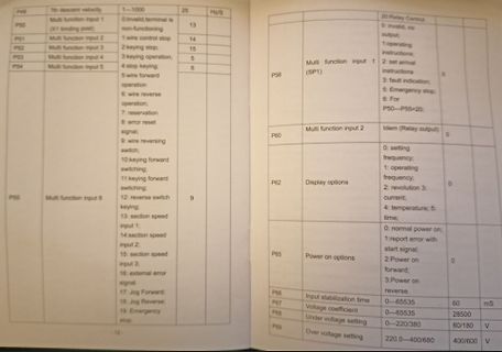
Multi function input 1 13 20: Relay Control (X1 binding post) 0:invalid, terminal is non-functioning P51 Multi function input 2 14 0:invalid, no output; 1 wire control stop P52 Multi function input 3 15 1:operating instructions; 2:keying stop, 3:keying operation P54 Multi function input 4 5 5:wire forward
in „Asynchronmaschine macht Geräusche: Klicken?“ · Analoge Elektronik und Schaltungstechnik · · Fotos
-
 Bild
Screenshot des Windows-Tools RamMap
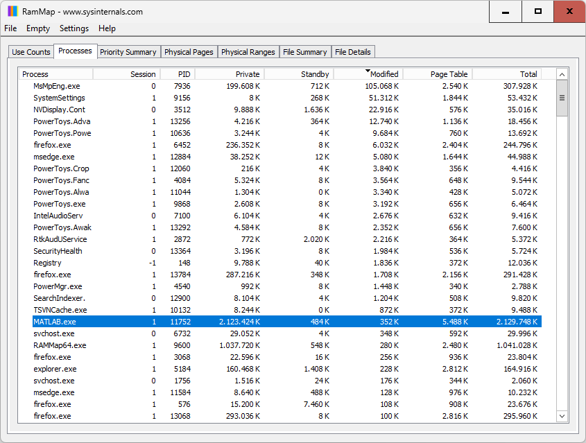
Physical Ranges File Summary File Details Process Session PID Private Standby Modified Page Table Total MsMpEng.exe 1 7936 199.608 K 712 K 105.608 K 2.540 K 307.928 K SystemSettings 1 9156 8 K 268 K 51.312 K 1.844 K 53.432 K NVDisplay.Cont 1 3512 9.888 K 1.636 K 22.916 K 576 K 35.016 K PowerToys.Adva 1 13256
in „Windows 11 langsam, wenn.“ · PC Hard- und Software · · Screenshots
-
Datei
mmc.c
#define CS PORTB.2 //SPCR = 0x51; => Die Initialisierung vom Hardware SPI müsste so stimmen oder? //SPCSR=0x00; unsigned char mmc_write_cmd(char *cmd) { unsigned char i; spi(0xFF); //Dummy delay 8 clocks CS=0; //MMC Chip Select aktivieren
in „MMC initialisieren“ · Mikrocontroller und Digitale Elektronik ·
-
PDF
Seiten_aus_st7565r.pdf
When the built-in power is being used immediately after turning on the power: * The target time of 5ms will result to vary depending on the panel characteristics and the capacitance of the smoothing capacitor. Therefore, we suggest you to conduct an operation check using the actual equipment. Notes: Refer
in „Init Problem mit KS0066 (Conrad)“ · Mikrocontroller und Digitale Elektronik ·
-
Datei
AnalogDeviceADXL346.asm
/* * AnalogDeviceADXL346.asm * * Created: 11.03.2014 11:51:01 * Author: birgit */ .nolist ; Turn listfile generation OFF .device attiny2313 ; Set device to ATTiny2313 .include "tn2313def.inc" ; Include file for ATTiny2313 .list ; Turn listfile generation ON
in „Minimum Initialization Sequence Attiny2313 und ADXL346“ · Mikrocontroller und Digitale Elektronik ·
-
PDF
TLE2426.PDF
TA= 25⋅C % % 30 – 2 – t t n n U U o 1.5 o 20 g g t t e e r 1 r e e P P 10 0.5 0 0 2.48 2.49 2.5 2.51 2.52 6 6.025 6.05 6.075 6.1 V – Output Voltage – V V – Output Voltage – V O O Figure 1 Figure 2 OUTPUT VOLTAGE ERROR OUTPUT VOLTAGE CHANGE vs vs FREE-AIR TEMPERATURE INPUT VOLTAGE 4 150 O = 0 VI= 40
in „Symmetrische Spannungsversorgung für OPV“ · Analoge Elektronik und Schaltungstechnik ·
-
PDF
dale-WSHM2818.pdf
b c b l l d c a b c l a b d e f l 0.138 0.210 0.020 0.024 0.143 0.210 0.026 0.105 Ø 0.020 0.024 (3.51) (5.33) (0.51) (0.61) (3.63) (5.33) (0.66) (2.67) (0.50) (0.61) Note • Sensing locations are based on the construction of the part; terminals are wrapped from the outside to underneath. These options
-
Datei
ATmega2560.xml
<TEXT51> <MASK>0x3F</MASK> <VALUE>0x1E</VALUE> <TEXT>Ext. Crystal Osc.; Frequency 8.0- MHz; Start-up time: 258 CK + 65 ms; [CKSEL=1110 SUT=01]</TEXT> </TEXT51> <TEXT52> <MASK>0x3F</MASK> <VALUE>0x2E</VALUE>
in „Eclipse AVR win32 komplett?“ · Mikrocontroller und Digitale Elektronik ·
-
PDF
OpAmp_MC3407x_KapazitiveLast.pdf
V in + V O 5.0 k 5.0 k 5.0 k - MC34071 t VO - MC34071 2.0 k V O 10 k 10 k 10 k + V RL CC 1.0 V 0.2 ms 4.0 V Delay Bit Switches 13 V/ms 25 V/ms (R-2R) Ladder Network 0.1 t Settling Time Delay 1.0 ms (8-Bits, 1/2 LSB) 1.0 ms Figure 44. Low Voltage Fast D/A Converter Figure 45. High Speed Low Voltage Comparator
in „Push/Pull in spannungsgeregelter Stromquelle / Frage zur Auslegung“ · Analoge Elektronik und Schaltungstechnik ·
-
PDF
DEM20485.pdf
08 09 0A 0B 0C 0D 0E 0F 10 11 12 13 SECOND LINE 40 41 42 43 44 45 46 47 48 49 4A 4B 4C 4D 4E 4F 50 51 52 53 THIRD LINE 14 15 16 17 18 19 1A 1B 1C 1D 1E 1F 20 21 22 23 24 25 26 27 FOURTH LINE 54 55 56 57 58 59 5A 5B 5C 5D 5E 5F 60 61 62 63 64 65 66 67 DD RAM ADDRESS VERSION : 0 6 DEM 20486 SYH-LY Product
in „LCD am I2C initialisieren“ · Mikrocontroller und Digitale Elektronik ·
-
PDF
Vierzeiliges_Display_DEM20488.pdf
DB2 DB1 DB0 Remark (fosc=270KHz) Clear Write”20H” to DDRAM. And set Display 0 0 0 0 0 0 0 0 0 1 1.52ms DDRAM address to “00H” fromAC Set DDRAM address to “00H” fromAC and return cursor to its original position if Return home 0 0 0 0 0 0 0 0 1 x 1.52ms shifted. The contents of DDRAM are not changed. Sets
in „Probleme mit LCD-Display“ · Mikrocontroller und Digitale Elektronik ·
-
PDF
DEM20488SYH-PY.PDF
DB2 DB1 DB0 Remark (fosc=270KHz) Clear Write”20H” to DDRAM. And set Display 0 0 0 0 0 0 0 0 0 1 1.52ms DDRAM address to “00H” fromAC Set DDRAM address to “00H” fromAC and return cursor to its original position if Return home 0 0 0 0 0 0 0 0 1 x 1.52ms shifted. The contents of DDRAM are not changed. Sets
in „LCD Problem im 4-Bit Modus“ · Mikrocontroller und Digitale Elektronik ·
-
PDF
dgFutaba_VFD-Text-M-M2425_EN.pdf
See Fig. 7) Table-8 Item Symbol Min. Max. Unit Delay Time for internal reset at power-up tRSTD 100 − ms Vcc Off Time tOFF 1 − ms Vcc 4.5V 0.2V tOFF RSTD STB Fig. 7. Power-Up Internal Reset Timing 3. MODE OF OPERATION The following modes of operation are selectable via jumpers (see section 6. jumper Settings
in „VFD auf 4 Bit-parallel-Mode stellen“ · Mikrocontroller und Digitale Elektronik ·
-
PDF
slas272d.pdf
option is used. 4. The mass erase duration generated by the flash timing generator is at least 11.1 ms. The cummulative mass erase time needed is 200 ms. This can be achieved by repeating the mass erase operation until the cumulative mass erase time is met (a minimum of 19 cycles may be required). f (
in „MSP430 Interrupt Port1“ · Mikrocontroller und Digitale Elektronik ·
-
 Bild
Screenshot einer Software zur Datenanalyse von Mikrocontrollern
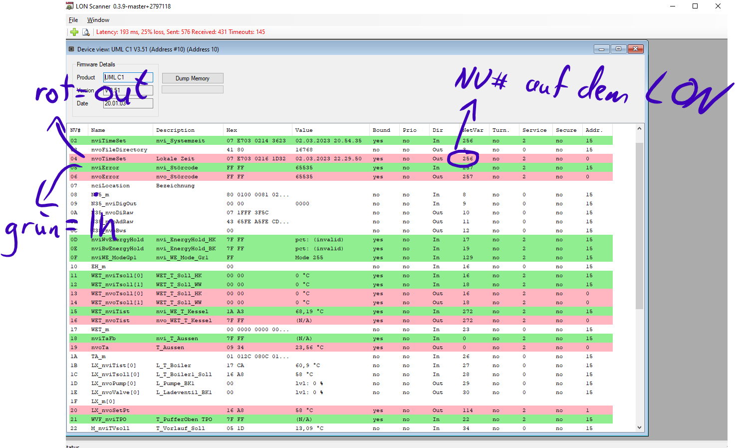
LON Scanner 0.3.9-master*2797118 File Window Latency: 193 ms, 25% loss, Sent: 576 Received: 431 Timeouts: 145 Device view: UML C1 V3.51 (Address #10) (Address 10) NVs Name Description Value Bound Prio Dir NetVar Turn. Service Addr. 02 nviTimeSet nvi_Systemzeit
in „LON Bus Windhager mitlesen/steuern“ · Softwareentwicklung · · Screenshots
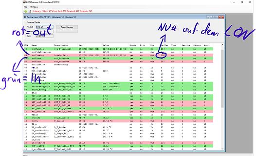
-
PDF
WH6165.pdf
Schnittstelle zum Datenlogger Impulskonstante: Optokopplerausgang und LED: 1000 Imp./kWh (Imp. Breite <= 30 ms) Abmessung: Breite: 2 TE = 36 mm, Höhe: 94 mm, Tiefe: 65 mm (nach DIN 43880 / EN 50022) Anschlüsse: Schraubklemmen bis 25 mm Gewicht: ca. 150 g Schutzart: Gehäuse IP51, Klemmen mit Deckel IP20 Umgebungstemperatur
-
PDF
STC15-English.pdf
Pre-scale value of Watchdog timer is shown as the bellowed table : P02 PS0 P00 Pre2scale WDT overfl39.3 mS @20MHz 0 0 1 4 78.6 mS 0 1 0 8 157.3 mS 0 1 1 16 314.6 mS 1 0 0 32 629.1 mS 1 0 1 64 1.25 S 1 1 0 128 2.5 S 1 1 1 256 5 S The WDT overflow time is determined by the following equation: WDT overflow time
in „Testbericht Elektronische Last“ · Analoge Elektronik und Schaltungstechnik ·
-
PDF
sv_2005_2.pdf
41 631,25 Pfarrkirchen 57 759,25 Regensburg 42 639,25 Rhön 49 695,25 Schnaitsee 54 735,25 Spessart 51 711,25 Würzburg 45 663,25 23 Satellitenkanäle Analoges Fernsehen Programm Satellit Transponder Frequenz Polarisation Zwischenfrequenz Das Erste Astra 1E 19 11,494 GHz horizontal 1.494 MHz oder 1.744
in „Kann mit einem Spektrumanalyser eine Sat-Anlage ausrichten?“ · Mikrocontroller und Digitale Elektronik ·
-
PDF
adxl202_beschl.sensor_analog.pdf
be added at these pins to T2 RSET implement low-pass filtering for antialiasing and noise reduc- 1 ms 125 k tion. The equation for the 3 dB bandwidth is: 2 ms 250 k 1 5 ms 625 k F –3dB= 10 ms 1.25 M (2 (32 k ) C(x, y) ) Note that the R should always be included, even if only an 5 F SET F–3dB = analog
in „Differenzverstärkerschaltung“ · Analoge Elektronik und Schaltungstechnik ·
-
PDF
OVC3860_RevE_PSKeys_Setting_v1.2.pdf
app_status:This parameter indicates the application status.(1~12) led_on_time: This parameter x 10ms indicates the led on time in 1 cycle . led_off_time: This parameter x 10ms indicates the led off time in 1 cycle. led_repeat_time: This parameter x 50ms indicates the led off time in 1 cycle. led_flash_num
in „A2DP Bluetooth Modul China eBay“ · HF, Funk und Felder ·