-
 Bild
Bild
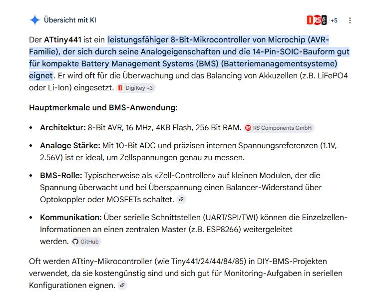
Text über ATtiny441 Mikrocontroller und BMS-Anwendung
Übersicht mit KI Der ATtiny441 ist ein leistungsfähiger 8-Bit-Mikrocontroller von Microchip (AVR-Familie), der sich durch seine Analogeigenschaften und die 14-Pin-SOIC-Bauform gut für kompakte Battery Management Systems (BMS)
in „alternativ Akku zum verbauten??“ · Analoge Elektronik und Schaltungstechnik · · Screenshots
-
Datei
owdevice_ATT13_DS18B20.c
volatile uint8_t cbuf; //Empfangspuffer fuer einen Befehl const uint8_t owid[8]={0x28,0xA2,0xD9,0x84,0x02,0x00,0x00,0x19}; volatile uint8_t bitp; //Zeiger auf das aktuelle Byte volatile uint8_t bytep; //Zeuger auf das aktuelle Bit volatile uint8_t scratchpad[9]={0x50,0x05,0x0,0x0,0x7f,0xff,0x00,0x10,0x0
in „1-Wire Slave auf AVR“ · Mikrocontroller und Digitale Elektronik ·
-
Datei
Resetter.asm
. 20 s nach Einschalten warten SLdt 181027 244 neu SLdt 200720 272 mit CLKPR, CLK per Interrupt; ATtiny85 Disclaimer: none. Sue me. ausgelegt fuer Extremfall: Ziel-AVR8 mit 32 KiHz-Quarz und Programm mit Clock-Prescaler 256: -> 32 Hz (= 32 KiHz /256/4) Kurzanleitung: -------------- Funktion: Chip-Erase
in „Microcontroller mit Python“ · Mikrocontroller und Digitale Elektronik ·
-
Datei
Fernbedienung_FB9_Tiny4313.c
irsnd.h" #ifndef F_CPU # error F_CPU unknown #endif void timer1_init (void) { #if defined (__AVR_ATtiny45__) || defined (__AVR_ATtiny85__) // ATtiny45 / ATtiny85: OCR1C = (F_CPU / F_INTERRUPTS / 4) - 1; // compare value: 1/15000 of CPU frequency, presc = 4 TCCR1 = (1 << CTC1) | (1 << CS11) | (1 << CS10
in „IR Fernbedienung mit IRSND“ · Mikrocontroller und Digitale Elektronik ·
-
Datei
readme.txt
Verwendung des Softwaremoduls kann somit mit: Compiler : avr-gcc (ab Version 4.8.1 getestet) MCU : ATtiny44 (sollte jedoch auch mit ATtiny24 und ATtiny84 funktionieren) Taktfrequenz MCU : 8MHz intern Fuses : Lo:0xE2 Hi:0xDF LEDs : WS2812b Betriebssystem : Linux IDE : Make betrieben werden. ____________
-
Datei
Original.c.c
/*************************************************************************************** Titel: ATtiny TPS Author: Christian Hottum File: ATtiny461A_TPS.c Version: 0.1 Datum: 09.01.2015 Software: AVR-GCC 4.3.3 Target: ATtiny461A DESCRIPTION Firmware für einen Tasten Programierbare Steuerung auf Basis
in „Ttiny 461a isp schaltung“ · Mikrocontroller und Digitale Elektronik ·
-
Datei
Defektfused.txt
Arduino: 1.8.13 (Windows 10), Board: "ATtiny25/45/85, ATtiny85, Internal 8 MHz" C:\Program Files (x86)\Arduino\hardware\tools\avr/bin/avrdude -CC:\Program Files (x86)\Arduino\hardware\tools\avr/etc/avrdude.conf -v -v -v -v -pattiny85 -cstk500v1
in „Projekt fertiggestellt: MP3 Player für Kinder auf ATTiny-Basis“ · Projekte & Code ·
-
Datei
uploadlog.txt
flash written avrdude.exe: verifying flash memory against C:\Users\franz\Documents\Atmel Studio\7.0\Attiny_Blink\Attiny_Blink\Debug\Attiny_Blink.hex: avrdude.exe: load data flash data from input file C:\Users\franz\Documents\Atmel Studio\7.0\Attiny_Blink\Attiny_Blink\Debug\Attiny_Blink.hex: avrdude.exe: input file C:\Users\franz\Documents\Atmel Studio\7.0\Attiny_Blink\Attiny_Blink\Debug\Attiny_Blink.hex contains 98 bytes avrdude.exe: reading on-chip flash data: Reading | avrdude.exe: Send: U [55] . [00] . [00] [20] avrdude.exe: Recv: . [14] avrdude.exe: Recv
in „Atmel Studio, Arduio ISP und Attiny“ · Mikrocontroller und Digitale Elektronik ·
-
PDF
ATTiny1624.pdf
ATtiny1624/1626/1627 Product Brief Introduction The ATtiny1624/1626/1627 microcontrollers of the tinyAVR 2 family are using the AVR CPU with hardware multiplier, running at up to 20 MHz, with 16 KB Flash,
in „Neues Produkt AtTiny1624“ · Mikrocontroller und Digitale Elektronik ·
-
Datei
main.c
SLEEP_MODE_PWR_DOWN); // set_sleep_mode(SLEEP_MODE_STANDBY); // sleep_mode(); ?-? } ISR(WDT_vect) // ATtiny841 //ISR(WATCHDOG_vect) // ATtiny84A { PORTA ^= (1<<PINA5); // toggelt LED 2 WDTCSR |= (1<<WDIE); } int main(void) { watchdogSetup(); sleepSetup(); DDRA=0b00100001; // DDR A auf Ausgang schalten PORTA
in „SLEEP und Watchdog mit Attiny 841“ · Mikrocontroller und Digitale Elektronik ·
-
Datei
usiTwiSlave.c
USI_START_VECTOR USI_START_vect # define USI_OVERFLOW_VECTOR USI_OVERFLOW_vect #endif #if defined(__AVR_ATtiny84__) | \ defined(__AVR_ATtiny44__) # define DDR_USI DDRA # define PORT_USI PORTA # define PIN_USI PINA # define PORT_USI_SDA PORTA6 # define PORT_USI_SCL PORTA4 # define PIN_USI_SDA PINA6 # define
in „Referenz von "usi_onReceiverPtr"“ · Mikrocontroller und Digitale Elektronik ·
-
PDF
AVR_Product_Update_November_2002.pdf
Emulation Tools Starter Kits ICE200 ICE10 ICE40 ICE50 JTAGICE AVRISP STK500 STK501 STK502 tinyAVR ATtiny11 • • • ATtiny12 • • • • ATtiny15 • • • ATtiny26 • • • • ATtiny28 • • AT90S AT90S1200 • • • • AT90S2323 • • • AT90S2343 • • • AT90S2313 • • • • AT90S4433 • • • • AT90S8515 • • • • AT90S8535 • • • •
in „Veraltete AVR's ?!“ · Mikrocontroller und Digitale Elektronik ·
-
Datei
intTest.lst
4.1 (C)2018 by DG4FAC ---------------------------------------------------------- Quelldatei: C:\ATtiny85 Lernpaket\Assembler-Files\intTest\intTest.asm Hexdatei: C:\ATtiny85 Lernpaket\Assembler-Files\intTest\intTest.hex Eepromdatei: C:\ATtiny85 Lernpaket\Assembler-Files\intTest\intTest.eep Kompiliert
in „attiny85 interrupt-behandlung“ · Mikrocontroller und Digitale Elektronik ·
-
Datei
telefonadapter.c
/* Programm für ATtiny25 * h#s Henrik Haftmann, TU Chemnitz, 31. März 2009 - 8. Oktober 2015 * tabsize = 8, encoding = utf-8 (ohne Windows-Header BOM) */ #include <avr/io.h> #include <avr/pgmspace.h> #include <avr/interrupt.h
in „HEX-File passt nicht in Attiny 25“ · Mikrocontroller und Digitale Elektronik ·
-
Datei
Fernbedienung_FB9_Tiny4313.c
sleep.h" #ifndef F_CPU # error F_CPU unknown #endif void timer1_init (void) { #if defined (__AVR_ATtiny45__) || defined (__AVR_ATtiny85__) // ATtiny45 / ATtiny85: OCR1C = (F_CPU / F_INTERRUPTS / 4) - 1; // compare value: 1/15000 of CPU frequency, presc = 4 TCCR1 = (1 << CTC1) | (1 << CS11) | (1 << CS10
in „IR Fernbedienung mit IRSND“ · Mikrocontroller und Digitale Elektronik ·
-
Datei
irsnd-main-avr.c
} // end gigaset specific code // IRSND starts here void timer1_init (void) { #if defined (__AVR_ATtiny45__) || defined (__AVR_ATtiny85__) // ATtiny45 / ATtiny85: OCR1C = (F_CPU / F_INTERRUPTS / 4) - 1; // compare value: 1/15000 of CPU frequency, presc = 4 TCCR1 = (1 << CTC1) | (1 << CS11) | (1 << CS10
in „Konzeption einer IR Fernbedienung“ · Mikrocontroller und Digitale Elektronik ·
-
Datei
mg.asm
37, -33, -29, -25, -22, -19, -17, -16, -15, -14, -12, -9 .db -4, 2, 11, 22, 34, 46, 57, 67, 75, 81, 84, 86, 87, 86, 86, 85 .db 85, 85, 86, 86, 87, 86, 84, 82, 78, 73, 69, 64, 60, 58, 56, 57 .db 59, 62, 66, 70, 75, 79, 83, 86, 89, 91, 92, 92, 92, 90, 86, 81 .db 73, 63, 52, 38, 24, 9, -5, -19, -31, -42,
in „Sequencer Prinzip ELM - Wavetable Melody Generator (ASM)“ · Mikrocontroller und Digitale Elektronik ·
-
PDF
ATtiny212_412-Errata-and-Clarification-DS40002114B.pdf
ATtiny212/412 ATtiny212/412 Silicon Errata and Data Sheet Clarification The ATtiny212/412 devices you have received conform functionally to the current device data sheet (DS40001911), except for the anomalies
in „Attiny412 Temperatur intern“ · Mikrocontroller und Digitale Elektronik ·
-
Datei
2._Versuch.txt
Program Files (x86)\Arduino\libraries -libraries C:\Users\Lenovo\Documents\Arduino\libraries -fqbn=attiny:avr:ATtinyX5:cpu=attiny85,clock=internal8 -vid-pid=1A86_7523 -ide-version=10813 -build-path C:\Users\Lenovo\AppData\Local\Temp\arduino_build_335700 -warnings=none -build-cache C:\Users\Lenovo\AppData
in „Projekt fertiggestellt: MP3 Player für Kinder auf ATTiny-Basis“ · Projekte & Code ·
-
Datei
timing.cpp
volatile unsigned long timer2_millis = 0; static unsigned char timer2_fract = 0; #if defined(__AVR_ATtiny24__) || defined(__AVR_ATtiny44__) || defined(__AVR_ATtiny84__) SIGNAL(TIM2_OVF_vect) #else SIGNAL(TIMER2_OVF_vect) #endif { // copy these to local variables so they can be stored in registers // (volatile
in „IRMP - Infrared Multi Protocol Decoder“ · Projekte & Code ·
-
Datei
irsnd-main-avr.c
} // end gigaset specific code // IRSND starts here void timer1_init (void) { #if defined (__AVR_ATtiny45__) || defined (__AVR_ATtiny85__) // ATtiny45 / ATtiny85: OCR1C = (F_CPU / F_INTERRUPTS / 4) - 1; // compare value: 1/15000 of CPU frequency, presc = 4 TCCR1 = (1 << CTC1) | (1 << CS11) | (1 << CS10
in „IR Fernbedienung mit IRSND“ · Mikrocontroller und Digitale Elektronik ·
-
Datei
PMSMtables.h
/* Variable Frequency Drive with AVR ATTiny25/45/85 */ /*! \file ********************************************************************* * * * by Matthias Schoeldgen - DC7UR * $Name: RELEASE_1_0 $ * $RCSfile: PMSMtables.h,v $ * $Date: 2012/06/
in „Theorie Wechselrichter 12V DC -> 230V AC“ · Analoge Elektronik und Schaltungstechnik ·
-
Datei
attiny24_mit_5_led.c
#ifndef F_CPU #define F_CPU 8000000UL #endif #define MCU attiny24 /* Fuses für den Dude: LFUSE = 62 HFUSE = d7 // Abweichung ggü Default (df): EESAVE EFUSE = ff */ #include <stdint.h> #include <avr/io.h> #include <util/delay.h> uint8_t i; void led(uint8_t ledNumber
in „ATtiny24-Rätsel, PB0 wird nicht high“ · Mikrocontroller und Digitale Elektronik ·
-
Datei
felermeldung.txt
Send: 0 [30] [20] avrdude: Send: 0 [30] [20] avrdude: Recv: . [14] avrdude: Recv: . [10] AVR Part : ATtiny85 Chip Erase delay : 400000 us PAGEL : P00 BS2 : P00 RESET disposition : possible i/o RETRY pulse : SCK serial program mode : yes parallel program mode : yes Timeout : 200 StabDelay : 100 CmdexeDelay
in „Fehler beim Flashen des ATtiny85 mit dem Arduino uno“ · Mikrocontroller und Digitale Elektronik ·
-
Datei
main.c
printbyte(data >> 8); printbyte(data); } #endif static void timer1_init (void) { #if defined (__AVR_ATtiny45__) || defined (__AVR_ATtiny85__) // ATtiny45 / ATtiny85: #if F_CPU >= 16000000L OCR1C = (F_CPU / F_INTERRUPTS / 8) - 1; // compare value: 1/15000 of CPU frequency, presc = 8 TCCR1 = (1 << CTC1) |
in „IRMP-Anwendung“ · Mikrocontroller und Digitale Elektronik ·
-
Datei
Netzmessung_TWI.cpp
on the ATmega2560 http://openenergymonitor.org/emon/node/2253#comment-11432 #elif defined (__AVR_ATtiny24__) || defined(__AVR_ATtiny44__) || defined(__AVR_ATtiny84__) ADMUX = _BV(MUX5) | _BV(MUX0); #elif defined (__AVR_ATtiny25__) || defined(__AVR_ATtiny45__) || defined(__AVR_ATtiny85__) ADMUX = _BV(
in „AVR Frequenzmessung, DS18S20“ · Mikrocontroller und Digitale Elektronik ·
-
Datei
tiny_oled_spi_3wire_b.ino
3wire.ino Demoprogramm zum Anbinden eines SSD1306 OLED-Displays mit nur 3 benoetigten I/O Leitungen des ATtiny-Controllers. Demoprogramm hier fuer ATtiny44/84. Programm sollte durch Abaenderung der Anschlusspins auch auf ATtiny45/85 lauffaehig sein, da die SPI-Schnittstelle nur mittels Bitbanging (und nicht
in „ATtiny85 benötige Taster und kein freier Port“ · Mikrocontroller und Digitale Elektronik ·
-
PDF
ATtiny261A_Complete.pdf
for each positive (CSn[2:0] = 7) or negative (CSn[2:0] = 6) edge it detects. See Table 11-4 on page 84 for details. 72 ATtiny261A/461A/861A 8197C–AVR–05/11 ATtiny261A/461A/861A Figure 11-3. T0 Pin Sampling Tn D Q D Q D Q Tn_sync Select Logic) LE clI/O Synchronization Edge Detector The synchronization
in „USI Interface als SPI Schnittstelle beim ATtiny261A“ · Mikrocontroller und Digitale Elektronik ·
-
Datei
dude5.4arduino_avr910.txt
0x1d = (unknown) Device code: 0x1e = (unknown) Device code: 0x1f = (unknown) Device code: 0x20 = ATtiny84 Device code: 0x21 = (unknown) Device code: 0x22 = (unknown) Device code: 0x23 = (unknown) Device code: 0x24 = (unknown) Device code: 0x25 = (unknown) Device code: 0x26 = (unknown) Device code: 0x27
in „avrdude - Probleme unter Mac OS X 10.7 (Lion)“ · Mikrocontroller und Digitale Elektronik ·
-
Datei
dude5.6_avr910.txt
0x1d = (unknown) Device code: 0x1e = (unknown) Device code: 0x1f = (unknown) Device code: 0x20 = ATtiny84 Device code: 0x21 = (unknown) Device code: 0x22 = (unknown) Device code: 0x23 = (unknown) Device code: 0x24 = (unknown) Device code: 0x25 = (unknown) Device code: 0x26 = (unknown) Device code: 0x27
in „avrdude - Probleme unter Mac OS X 10.7 (Lion)“ · Mikrocontroller und Digitale Elektronik ·
-
Datei
dude54arduino.txt
0x1d = (unknown) Device code: 0x1e = (unknown) Device code: 0x1f = (unknown) Device code: 0x20 = ATtiny84 Device code: 0x21 = (unknown) Device code: 0x22 = (unknown) Device code: 0x23 = (unknown) Device code: 0x24 = (unknown) Device code: 0x25 = (unknown) Device code: 0x26 = (unknown) Device code: 0x27
in „avrdude - Probleme unter Mac OS X 10.7 (Lion)“ · Mikrocontroller und Digitale Elektronik ·
-
PDF
ATtiny841_Datasheet.pdf
(f clk_I/O) clk I/O clk (clk /8) I/O TCNTn MAX - 1 MAX BOTTOM BOTTOM + 1 TOVn Figure 11-10 on page 84 shows the setting of OCF0B in all modes and OCF0A in all modes except CTC mode and PWM mode, where OCR0A is TOP. ATtiny441/841 [DATASHEET] 83 8495H–AVR–05/2014 Figure 11-10.Timer/Counter Timing Diagram
in „TOCPMSA1 und TOCPMCOE Verhalten beim Attiny 841“ · Mikrocontroller und Digitale Elektronik ·
-
PDF
ATtiny441_841.pdf
(f clk_I/O) clk I/O clk (clk /8) I/O TCNTn MAX - 1 MAX BOTTOM BOTTOM + 1 TOVn Figure 11-10 on page 84 shows the setting of OCF0B in all modes and OCF0A in all modes except CTC mode and PWM mode, where OCR0A is TOP. ATtiny441/841 [DATASHEET] 83 8495H–AVR–05/2014 Figure 11-10.Timer/Counter Timing Diagram
in „Suche nach ATtiny mit ADC und Gain > 20x“ · Mikrocontroller und Digitale Elektronik ·
-
PDF
ATtiny841_Datasheet.pdf
(f clk_I/O) clk I/O clk (clk /8) I/O TCNTn MAX - 1 MAX BOTTOM BOTTOM + 1 TOVn Figure 11-10 on page 84 shows the setting of OCF0B in all modes and OCF0A in all modes except CTC mode and PWM mode, where OCR0A is TOP. ATtiny441/841 [DATASHEET] 83 8495H–AVR–05/2014 Figure 11-10.Timer/Counter Timing Diagram
in „sleep und Interrupt“ · Mikrocontroller und Digitale Elektronik ·
-
PDF
ATtiny841_Datasheet.pdf
(f clk_I/O) clk I/O clk (clk /8) I/O TCNTn MAX - 1 MAX BOTTOM BOTTOM + 1 TOVn Figure 11-10 on page 84 shows the setting of OCF0B in all modes and OCF0A in all modes except CTC mode and PWM mode, where OCR0A is TOP. ATtiny441/841 [DATASHEET] 83 8495H–AVR–05/2014 Figure 11-10.Timer/Counter Timing Diagram
in „Takt-Vorskalierungsregister beim Attiny841“ · Mikrocontroller und Digitale Elektronik ·
-
PDF
kicad_8450_dcm_liste_neu_v3.pdf
SRAM, 64B EEPROM ATTINY5-TS SOT-23-6, 512B Flash, 32B SRAM, No EEPROM, ADC ATTINY84-20MU QFN/MLF20, 8k Flash, 512B SRAM, 512B EEPROM, dW ATTINY84-20PU PDIP14, 8k Flash, 512B SRAM, 512B EEPROM, dW ATTINY84-20SSU SO14, 8k Flash
in „KiCAD Eeschema, Bibliotheksdokumentation *.dcm als PDF-Datei“ · Platinen ·
-
 Bild
Bild
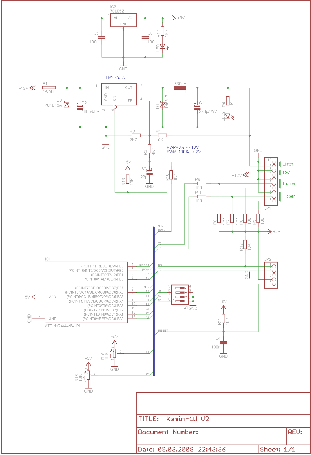
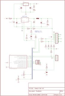
Schaltplan mit ATtiny24/44-84 Mikrocontroller und LM2575-ADJ Spannungsregler
10K, R18, R9 100, R10 100, GND, 12V, Lüfter, T unten, T oben, JP1, +5V, R15 10K, R16 10K, GND, IC1 ATtiny24/44-84, RESET, PB3, PB2, PB1, PA0, PA1, PA2, PA3, PA4, PA5, PA6, PA7, PB0, PB4, PB5, PB6, PB7, RESET, GND, C4 100n, +5V, TITLE: Kamin-1W V2, Document Number:, REU:, Date: 09.03.2008 22:13:36, Sheet
in „DC/DC LM317 richtig einbauen“ · Analoge Elektronik und Schaltungstechnik · · Schaltpläne
-
PDF
tiny13.pdf
Conversion) (Cycles) First conversion 13.5 25 Normal conversions 1.5 13 Auto Triggered conversions 2 13.5 84 ATtiny13 2535E–AVR–10/04 ATtiny13 Changing Channel or The MUXn and REFS1:0 bits in the ADMUX Register are single buffered through a tem- Reference Selection porary register to which the CPU has random
in „ATtiny13 Datenblatt External Clock Source on T0-Pin“ · Mikrocontroller und Digitale Elektronik ·
-
PDF
Atiny2313.pdf
less than half the system clock frequency (f < f /2) given a 50/50% duty cycle. Since ExtClk clk_I/O 84 ATtiny2313/V 2543I–AVR–04/06 ATtiny2313/V the edge detector uses sampling, the maximum frequency of an external clock it can detect is half the sampling frequency (Nyquist sampling theorem). However,
in „Suche tutorial“ · Mikrocontroller und Digitale Elektronik ·
-
Datei
mpx_2digit_uart.c
-------- mpx_2digit_uart.c 2 stellige gemultiplexte 7-Segmentanzeige mit gemeinsamer Anode MCU : attiny84 F_CPU : 8000000 07.02.2022 by R. Seelig ------------------------------------------------------------ */ #include <util/delay.h> #include <avr/io.h> #include <util/delay.h> #include <avr/interrupt.h> #include <stdbool.h> #include "mpx_2conc.h" /* ATtiny 24 / 44 / 84 Anschlusspins IC +-----------+ Vcc | 1 A 14 | GND PB0 - PCINT8 - XTAL1 - SCI - CLKI | 2 T 13 | PA0 - ADC0 - AREF - PCINT0 PB1 - PCINT9 - XTAL2 | 3 t 12 | PA1 - ADC1 - AIN0 - PCINT1 PB3
in „7 Segment Anzeige auf verschiedenen Ports“ · Mikrocontroller und Digitale Elektronik ·
-
Datei
wiring.c
volatile unsigned long timer0_millis = 0; static unsigned char timer0_fract = 0; #if defined(__AVR_ATtiny24__) || defined(__AVR_ATtiny44__) || defined(__AVR_ATtiny84__) SIGNAL(TIM0_OVF_vect) #else SIGNAL(TIMER0_OVF_vect) #endif { // copy these to local variables so they can be stored in registers // (volatile
in „IRMP - Infrared Multi Protocol Decoder“ · Projekte & Code ·
-
Datei
Devices.txt
C-EUC1812 3 C-EU102-054X133 3 C-EU025-050X050 3 CAP-5 3 C7.5/3 3 C2.5/6 3 BZX90 3 BZD23 3 BSS97 3 BSS84 3 BLITZ_250WS 3 BF245 3 BD243 3 BC556 3 BC327_SMD 3 BC327-25 3 BAT19 3 BAS40-04 3 BAS15 3 ATMEGA644A 3 AT90S8515P 3 AT90S4433P 3 AT8C51SND1A-PLCC84 3 AD1857 3 AB9V 3 9450-1 3 93LC46SM 3 90G-2 3 87758
in „[KiCad] Bibliotheksaufbau - Konzeptideen gesucht“ · Platinen ·
-
Datei
VirtualWire.cpp
defined #endif #include "VirtualWire.h" #include <util/crc16.h> #undef TIMER_VECTOR #ifdef __AVR_ATtiny85__ # define TIMER_VECTOR TIM0_COMPA_vect #elif defined(__AVR_ATtiny84__) || defined(__AVR_ATtiny24__) || defined(__AVR_ATtiny44__) // Why can't Atmel make consistent? # define TIMER_VECTOR TIM1_COMPA_vect
in „Korrigierte "VirtualWire" Library für Attiny84 / 85“ · Projekte & Code ·
-
Datei
avr_sim_deviceu.pas
ADC3', {2} 'ATtiny11'+ { 1 } '*PB5 RESET'+ { 2 } '*PB3 XTAL1'+ { 3 } '*PB4 XTAL2'+ { 4 } '*GND'+ { 5 } '*PB0 AIN0'+ { 6 } '*PB1 INT0 AIN1'+ { 7 } '*PB2 T0'+ { 8 } '*VCC', {3} 'ATtiny12'+ { 1 } '*PB5 RESET'+ { 2 } '*PB3
-
Datei
mega8.txt
Schaltung : SPI: MOSI, SCK ATMega8 zu ATTinys, ISP und LCD-shielt lt. Datenblatt B3,B4,B5 ; ATMega8 - ATTiny2313 ; C1 - B0 ; C2 - B0 ; C3 - B1 ; ATMega8 - LCD-shield ; C0 - A0 ADC für Joystick ; D2 - RST Taster zur Umschaltung auf Programmierung ; D4 - D4 Displaycontroller-Umschaltung ; D5 - D5 Displaycontroller
in „SPI Kopplung von ATmega8 und ATtiny 2313“ · Projekte & Code ·
-
Datei
rainbow.c
------------------------------------------------------------------- */ #ifdef TIM1_COMPA_vect // ATtiny84 ISR(TIM1_COMPA_vect) #else ISR(TIMER1_COMPA_vect) #endif { PORTB ^= (1 <<PB1); (void) irmp_ISR(); // call irmp ISR } ISR(TIMER2_COMP_vect) //10ms Tick fuer Delays / Aufrufe { static uint16_t i10ms_Count
in „Lightweight WS2811/WS2812 Library“ · Mikrocontroller und Digitale Elektronik ·
-
Datei
Tiny_Lighthouse.c
the 20ms period with PWM for generating the trigger pulse F_CPU = 1600000 Hz as the Tiny runs in ATTIny15 compatibility mode */ #include <avr/io.h> #include <avr/eeprom.h> #include <avr/interrupt.h> #include <avr/pgmspace.h> #include <util/delay.h> typedef struct LighthouseFlags { uint8_t Direction:
in „LED Fader mit NE555 fadet nicht“ · Analoge Elektronik und Schaltungstechnik ·
-
 Bild
Bild
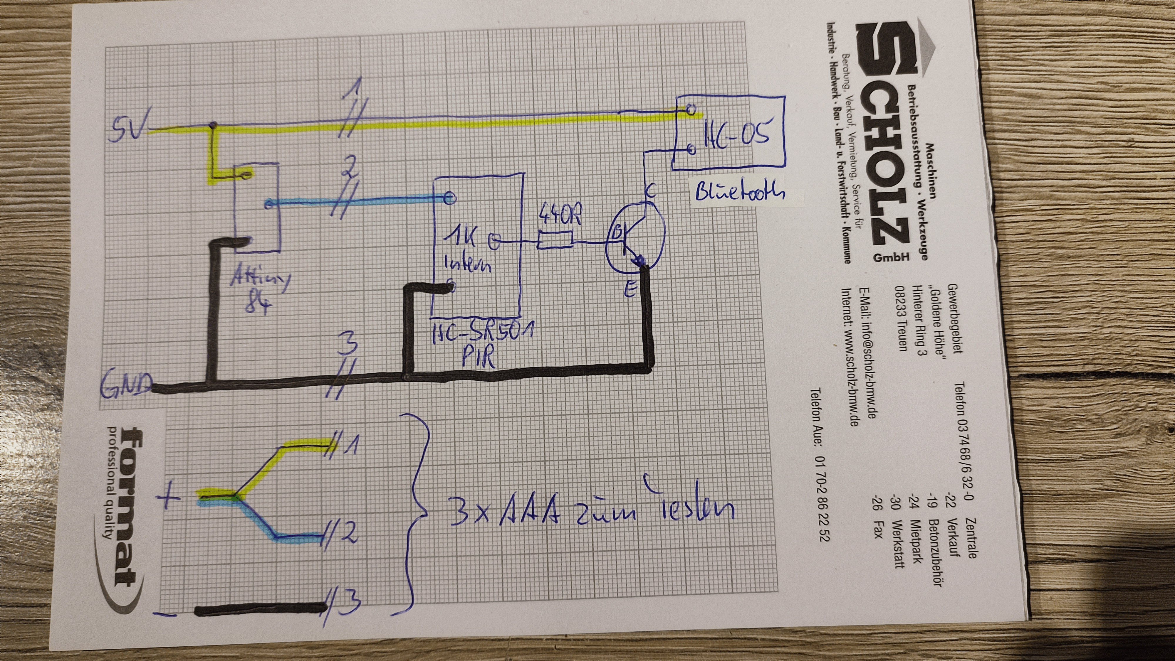
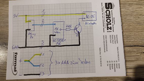
Handgezeichneter Schaltplan auf Millimeterpapier
5V, HC-05, Bluetooth, 440R, 1K, Attiny 84, Intern, GND, HC-SR501, PIR, 3x AAA zum testen, format professional quality, SCHOLZ Maschinen - Werkzeuge GmbH
in „Mit PIR HC-SR501 ein BT HC-05 schalten“ · Analoge Elektronik und Schaltungstechnik · · Fotos
-
Datei
test.c
/* testprogramm for generating a PWM - Singal */ // Microcontroller ATTINY44A #include <avr/io.h> #include <avr/interrupt.h> #include <util/delay.h> #include "AttinyPWM.h" #include "Typedef.h" #define divider 1 volatile uint8_t pwm_flag; int main(void) { // first square sinwave
in „PWM mit Interrupts steuern“ · Mikrocontroller und Digitale Elektronik ·
-
Datei
Values.txt
3 Ratio-2 3 Ratio-10 3 PWR-MCU 3 PWR-EXT 3 Program 3 POWERSUPPLY 3 PORTA / ADC 3 PINHD-2X3 3 PIC16F84AP 3 PC317 3 pad 3 P7 3 P600 3 P19 3 OPA544T 3 NV2R 3 NDC7002N 3 MOC3041 3 MEGA8 3 MEGA168-P 3 MAX481CPA 3 MAKEUP-C 3 MAGJACK 3 MAB5SH 3 LM1458N 3 link attack 3 LCD 3 L6207N 3 KLEMM3 3 IRFD9210 3 IR2101SS
in „[KiCad] Bibliotheksaufbau - Konzeptideen gesucht“ · Platinen ·