-
Datei
lcdcon_ft245_4bit.asm
Speicher geladen. * ;* Aufgrund der hohen Datenrate des Parallelports und der LCD Ausgang, * ;* läuft der AVR mit >10MHz und steuert das LCD mit bis zu 100Hz an. * ;* Wird nur ein 32kB SRAM verwendet, muss der Anschluss Q8 (A7) des 74x573 * ;* übersprungen werden. Dann sollte man bei XMax den Wert auf 128 stellen
in „LCD Controller für 640x480 LCD mit mega8515“ · Projekte & Code ·
-
Datei
CFD_blinken.asm
; SLdt 201020 ; Clock Failure Detection ; Antippen von J215 auf 'AVR128DB48 Curiosity Nano' .include "AVR128DB48def.inc" .def tmp0 = r16 .macro CCP ldi tmp0,CPU_CCP_IOREG_gc sts CPU_CCP,tmp0 .endmacro rjmp reset .org CLKCTRL_CFD_vect sbi VPORTB_IN,3 rcall blinken ; langsamer
in „AVR128DB - Clock Failure Detection“ · Mikrocontroller und Digitale Elektronik ·
-
Datei
lib-mfv.c
***************** //* A P P L I C A T I O N N O T E F O R T H E A V R F A M I L Y //* //* Number : AVR314 //* File Name : "dtmf.c" //* Title : DTMF Generator //* Date : 00.06.27 //* Version : 1.0 //* Target MCU : Any AVR with SRAM, 8 I/O pins and PWM //* //* DESCRIPTION //* This Application note describes
in „DTMF und ATMEGA 16“ · Mikrocontroller und Digitale Elektronik ·
-
Datei
blink.c
, 0, 0, 0, 0, 0, 0, 0, 0, 0, 0, 0, 0, 0, 0, 0, 0, 0,}; unsigned char movie3[] = {0, 0, 0, 0, 0, 0, 128, 128, 0, 0, 0, 0, 0, 0, 0, 0, 0, 0,}; unsigned char movie4[] = {0, 0, 0, 0, 0, 128, 192, 192, 128, 0, 0, 0, 0, 0, 0, 0, 0, 0,}; unsigned char movie5[] = {0, 0, 0, 0, 128, 192, 224, 224, 192, 128, 0,
in „Probleme mit Variablenplatz/Arrays“ · Mikrocontroller und Digitale Elektronik ·
-
Datei
lcdcon_ft245_4bit320.asm
Speicher geladen. * ;* Aufgrund der hohen Datenrate des Parallelports und der LCD Ausgang, * ;* läuft der AVR mit >10MHz und steuert das LCD mit bis zu 100Hz an. * ;* Wird nur ein 32kB SRAM verwendet, muss der Anschluss Q8 (A7) des 74x573 * ;* übersprungen werden. Dann sollte man bei XMax den Wert auf 128 stellen
in „LCD Controller für 640x480 LCD mit mega8515“ · Projekte & Code ·
-
Datei
lcdcon_ft245_4bit320.asm
Speicher geladen. * ;* Aufgrund der hohen Datenrate des Parallelports und der LCD Ausgang, * ;* läuft der AVR mit >10MHz und steuert das LCD mit bis zu 100Hz an. * ;* Wird nur ein 32kB SRAM verwendet, muss der Anschluss Q8 (A7) des 74x573 * ;* übersprungen werden. Dann sollte man bei XMax den Wert auf 128 stellen
in „LCD Controller für 640x480 LCD mit mega8515“ · Projekte & Code ·
-
PDF
doc7593.pdf
Section 6.10.2 for PLL interface). 48 ATmega32U6/AT90USB64/128 7593J–AVR–03/09 ATmega32U6/AT90USB64/128 Figure 6-4. PLL Clocking System PLOCK PLLE Lock Detector clk PLL clock 2MHz PLL clk Prescaler 24x USB (48MHz) XTAL1 XTAL2 OSCILLATORS
in „Problem mit dem TC4469“ · Mikrocontroller und Digitale Elektronik ·
-
Datei
Values.txt
BC307 1 BAT49 1 BAT46 1 BAT45 1 BAT42 1 BAS216 1 BACK_LIGHT 1 B82131 1 B80C1500 1 B40C1500 1 B2,54 1 AVR_XMEGA_A3_ 1 AVR-JTAG-10 1 AVR ISP 1 AVR 1 Aux_In 1 AUX 1 Ausgang 1 AtTINY45 1 ATTINY28 1 ATTINY26P 1 AT Tiny26 1 ATTINY24 1 ATTINY2313-20P 1 ATtiny2313 1 ATMEGA8-16P 1 ATMEGA640-16AU 1 ATMEGA48-20A 1 ATMEGA32U4-AU 1 ATMEGA2560-16AU 1 AT_MEGA16P 1 ATMEGA168-20A 1 ATMEGA164-20A 1 ATMEGA128_TQPF 1 ATiny2313 1 AT93C46 1 AT91SAM7X512-AU 1 AT91SAM7S128-AU 1 AT91RM9200_PQFP 1 AT90S2333P 1 AT90S2313P - War jetzt nur ein Beispiel-AVR 1 AT90S1200P 1 AT8C51SND1C 1 AT89S51 1 AT89C52P6 1 AT45DB321
in „[KiCad] Bibliotheksaufbau - Konzeptideen gesucht“ · Platinen ·
-
Datei
uart.c
define UART0_BIT_TXEN TXEN #define UART0_BIT_UCSZ0 UCSZ0 #define UART0_BIT_UCSZ1 UCSZ1 #elif defined(__AVR_ATmega48__) || defined(__AVR_ATmega48A__) || defined(__AVR_ATmega48P__) || defined(__AVR_ATmega48PA__) || defined(__AVR_ATmega48PB__) || \ defined(__AVR_ATmega88__) || defined(__AVR_ATmega88A__) ||
in „Timerberechnung die hunderste“ · Mikrocontroller und Digitale Elektronik ·
-
Datei
uart.c
define UART0_BIT_TXEN TXEN #define UART0_BIT_UCSZ0 UCSZ0 #define UART0_BIT_UCSZ1 UCSZ1 #elif defined(__AVR_ATmega48__) || defined(__AVR_ATmega48A__) || defined(__AVR_ATmega48P__) || defined(__AVR_ATmega48PA__) || defined(__AVR_ATmega48PB__) || \ defined(__AVR_ATmega88__) || defined(__AVR_ATmega88A__) ||
in „Fehler beim kompilieren des Bootloadertoutorials in C“ · Mikrocontroller und Digitale Elektronik ·
-
Datei
uart.c
define UART0_BIT_TXEN TXEN #define UART0_BIT_UCSZ0 UCSZ0 #define UART0_BIT_UCSZ1 UCSZ1 #elif defined(__AVR_ATmega48__) || defined(__AVR_ATmega48A__) || defined(__AVR_ATmega48P__) || defined(__AVR_ATmega48PA__) || defined(__AVR_ATmega48PB__) || \ defined(__AVR_ATmega88__) || defined(__AVR_ATmega88A__) ||
in „Wie macht man solche Lichtmodes? Lauflicht, PWM und Co“ · Mikrocontroller und Digitale Elektronik ·
-
 Bild
Bild
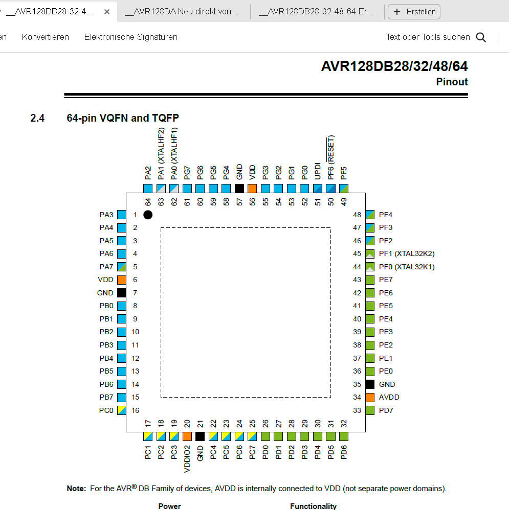
Pinbelegung AVR128DB28/32/48/64 VQFN und TQFP
AVR128DB28/32/48/64 Pinout 2.4 64-pin VQFN and TQFP PA2, PA1 (XTALHF), PA0 (XTALHF), PG7, PG6, PG4, VDD, PG3, PG2, PG1, UPD, PF6 (RESET), PF5, PF4, PF3, PF2, PF1, PF0 (XTAL32K1), PE7, PE6, PE5, PE4, PE3
in „AVR128DA64 TCA1 funktioniert nicht mit alternativen Output?“ · Mikrocontroller und Digitale Elektronik · · Screenshots
-
Datei
5110.c
#include <avr/io.h> #include <stdint.h> #include <inttypes.h> #include <avr/pgmspace.h> /* Anschluss des 5110-LCDs am AtMega8 * AVR => LCD * PC0 => D/C (1) * PC1 => SCLK (2) * PC2 => SDIN (3) * PC3 => RES (4) */
in „Anfängerprobleme mit PROGMEM“ · Mikrocontroller und Digitale Elektronik ·
-
Datei
sd-reader_20090330_mega328.patch
Revision 146) @@ -74,16 +74,19 @@ /* defines for customisation of sd/mmc port access */ #if defined(__AVR_ATmega8__) || \ defined(__AVR_ATmega48__) || \ + defined(__AVR_ATmega48P__) || \ defined(__AVR_ATmega88__) || \ + defined(__AVR_ATmega88P__) || \ defined(__AVR_ATmega168__) || \ - defined(__AVR_ATmega328
-
Datei
ODM100.c
******************************* * Processor : ATmega32 @ 8 MHz * Compiler : IAR (V4.30D) & GCC (WinAVR Version 10-01-2010) * Dot Matrix : 128 RGB x 128 * Driver IC : SSD1351 (Solomon Systech) * Interface : 8-bit 8080 Parallel ***************************************************************************
in „Frage zum ODM100 OLED Bausatz von ELV“ · Mikrocontroller und Digitale Elektronik ·
-
Datei
oled1.c
******************************* * Processor : ATmega32 @ 8 MHz * Compiler : IAR (V4.30D) & GCC (WinAVR Version 10-01-2010) * Dot Matrix : 128 RGB x 128 * Driver IC : SSD1351 (Solomon Systech) * Interface : 8-bit 8080 Parallel ***************************************************************************
in „AVR Oled Display odm 100-Wie ansteuern?“ · Mikrocontroller und Digitale Elektronik ·
-
Datei
oled.c
******************************* * Processor : ATmega32 @ 8 MHz * Compiler : IAR (V4.30D) & GCC (WinAVR Version 10-01-2010) * Dot Matrix : 128 RGB x 128 * Driver IC : SSD1351 (Solomon Systech) * Interface : 8-bit 8080 Parallel ***************************************************************************
in „ODM100 OLED bleibt schwarz“ · Mikrocontroller und Digitale Elektronik ·
-
Datei
ODM100.c
******************************* * Processor : ATmega32 @ 8 MHz * Compiler : IAR (V4.30D) & GCC (WinAVR Version 10-01-2010) * Dot Matrix : 128 RGB x 128 * Driver IC : SSD1351 (Solomon Systech) * Interface : 8-bit 8080 Parallel ***************************************************************************
in „SSD 1351 - OLED ansteuern“ · Mikrocontroller und Digitale Elektronik ·
-
PDF
ATMEGA_128.pdf
1 1 1 2 ) C S C N N N N ( C ( T( / O O L / 1 1 ( 2 T T C D D D C ( ( X T ( ( ( Overview The ATmega128 is a low-power CMOS 8-bit microcontroller based on the AVR enhanced RISC architecture. By executing powerful instructions in a single clock cycle, the ATmega128 achieves throughputs approaching 1 MIPS
in „ATMEGA128 Board im Neuhold Newsletter 2/2011“ · Mikrocontroller und Digitale Elektronik ·
-
PDF
AVRDUDE-doc-5.5.pdf
Command Line Options 11 2.2 Example Command Line Invocations Download the file diag.hex to the ATmega128 chip using the STK500 programmer con- nected to the default serial port: ☛ ✟ % avrdude -p m128 -c stk500 -e -U flash:w:diag.hex avrdude: AVR device initialized and ready to accept instructions Reading
in „USB-ISP PRogrammer unter Ubuntu“ · PC Hard- und Software ·
-
PDF
avr-gcc_14_rodata.pdf
Microchip Studio 7 Notiz für mich, Programm: Frequenzmesser mit AVR128DB48 Flags: -Os -ffunction-sections -fdata-sections -fpack-struct -fshort-enums -Wall -Wundef -c -flto -v avr-gcc binutils avrLibC zusätzliche Flags Flash RAM Bytes 7.5.0 2.40 2.1 -std=c++17 5220
in „GCC v14 Release“ · Mikrocontroller und Digitale Elektronik ·
-
Datei
HelloWorld.ino
_128X32 u8g(U8G_I2C_OPT_NONE); // I2C / TWI //U8GLIB_SSD1306_64X48 u8g(13, 11, 10, 9); // SW SPI Com: SCK = 13, MOSI = 11, CS = 10, A0 = 9 //U8GLIB_SSD1306_64X48 u8g(10, 9); // HW SPI Com: CS = 10, A0 = 9 (Hardware Pins are SCK = 13 and MOSI = 11) //U8GLIB_SSD1306_64X48 u8g(U8G_I2C_OPT_NONE); // I2C / TWI //U8GLIB_SH1106_128X64 u8g(13, 11, 10, 9); // SW SPI Com: SCK = 13, MOSI = 11, CS = 10, A0 = 9 //U8GLIB_SH1106_128X64 u8g(4, 5, 6, 7); // SW SPI Com: SCK = 4, MOSI
in „Arduino OLED Display Ansteuern & "Hello World" Programme gehen nicht.“ · Softwareentwicklung ·
-
PDF
Atmega128_doc2467.pdf
floating or have an analog signal level close to CC /2, the input buffer will use excessive power. 48 ATmega128 2467R–AVR–06/08 ATmega128 JTAG Interface and If the On-chip debug system is enabled by the OCDEN Fuse and the chip enter Power down or On-chip Debug Power save sleep mode, the main clock source
in „ATMEGA128 Timer“ · Mikrocontroller und Digitale Elektronik ·
-
PDF
XPLAIN_Shematic.pdf
TILLER D NORWAY Date: 08.05.2009 15:10:18 PAGE: 1 of 5 Document number: A08-0551 Revision: A TITLE: AVR1907: Xplain evaluation board, Top-Level Xplain.SchDoc 1 2 3 4 5 6 7 8 1 2 3 4 5 6 7 8 2 3 1 1 T T JTAG/PDIInterface PQ2 NTC_EN XMEGA_PDI_DATA XMEGA_PDI_DATA XMEGA_RESET_PDI_CLK XMEGA_RESET_PDI_CLK PQ3
in „Xplain: Schaltplan gesucht“ · Mikrocontroller und Digitale Elektronik ·
-
Datei
dtmf.asm
;*************************************************************************** ;* ;* Number : nach AVR314 ;* File Name : "dtmf_geb_m8a.asm" ;* Title : DTMF Generator ;* Datum : 16.02.2006 ;* Version : a ;* Target MCU : Any AVR with SRAM, 8 I/O pins and PWM ;* ;* This Application note describes how to
in „DTMF erzeugen Attiny2313“ · Mikrocontroller und Digitale Elektronik ·
-
Datei
main.c
#include <stdint.h> #include <avr/io.h> #include <avr/interrupt.h> /* for sei() */ #include <util/delay.h> /* for _delay_ms() */ #define DDRregister DDRB #define PORTled PORTB #define Arraysize 255 volatile uint8_t a; uint8_t *pointera
in „Probleme 3 PWM mit attiny13“ · Mikrocontroller und Digitale Elektronik ·
-
PDF
usb-isp_installation_de.pdf
EEPROM, Fusebits, Lockbits schreiben und lesen, Chip erase, OSCCAL-Register lesen Protokoll - STK500v2 (AVR-Studio bis Version 4.18 anwendbar) Softwareunterstützung - AVR-Studio (COM1...COM9) maximal bis Version 4.18 - AVRDUDE - Bascom mit der Einstellung Options ->Programmer = STK500 C:\Programme\Atmel\AVR
in „Atmega läuft nur mit Programmer“ · Mikrocontroller und Digitale Elektronik ·
-
PDF
usb-isp_installation_de.pdf
EEPROM, Fusebits, Lockbits schreiben und lesen, Chip erase, OSCCAL-Register lesen Protokoll - STK500v2 (AVR-Studio bis Version 4.18 anwendbar) Softwareunterstützung - AVR-Studio (COM1...COM9) maximal bis Version 4.18 - AVRDUDE - Bascom mit der Einstellung Options ->Programmer = STK500 C:\Programme\Atmel\AVR
in „Diamex USB ISP Programmer“ · Mikrocontroller und Digitale Elektronik ·
-
Datei
lcdconpar.asm
, 0 , 252 , 0 , 0 , 0 , 0 .db 0 , 0 , 0 , 0 , 0 , 48 , 48 , 0 .db 6 , 12 , 24 , 48 , 96 , 192 , 128 , 0 .db 124 , 198 , 206 , 222 , 246 , 230 , 124 , 0 .db 48 , 112 , 48 , 48 , 48 , 48 , 252 , 0 .db 120 , 204 , 12 , 56 , 96 , 204 , 252 , 0 .db 120 , 204
in „LCD Controller für 640x480 LCD mit mega8515“ · Projekte & Code ·
-
Datei
benchtest3.txt
4,37 | 11084 | ------------------------------------------------------------------- Apfelmaennchen 160x128 Pixel Optimierung -Os 62,9s / 6388 Byte -O3 62,8s / 7664 Byte Benchmark Ergebnisse ATmega328 Compiler: avr-gcc Version 7.3.0 | Zeit [s] | Optimierung | int8 | int16 | int32 | float | Codegroesse | -
in „CH32V003, float wirklich langsam?“ · Mikrocontroller und Digitale Elektronik ·
-
Datei
benchtest3.txt
4,37 | 11084 | ------------------------------------------------------------------- Apfelmaennchen 160x128 Pixel Optimierung -Os 62,9s / 6388 Byte -O3 62,8s / 7664 Byte Benchmark Ergebnisse ATmega328 Compiler: avr-gcc Version 7.3.0 | Zeit [s] | Optimierung | int8 | int16 | int32 | float | Codegroesse | -
in „CH32V003, float wirklich langsam?“ · Mikrocontroller und Digitale Elektronik ·
-
Datei
AVRrescue.c
includes into one file * Removed second button (had no function) */ #include <inttypes.h> #include <avr/io.h> #include <avr/interrupt.h> #include <avr/eeprom.h> #include <avr/pgmspace.h> #ifndef F_CPU #define F_CPU 8000000UL // 8 MHz int RC osz #endif #include <util/delay.h> // Fuse settings for 8535
in „AVR-Rescue: standalone Parallel HV-Programmer“ · Projekte & Code ·
-
Datei
main.c
#include <avr/io.h> #include <avr/interrupt.h> #include <avr/pgmspace.h> #include <avr/eeprom.h> #include <stdlib.h> #include "global.h" #include "rf01.h" #define BAUD 9600UL // USART Baudrate // Berechnungen #define
-
Datei
fcntl.lst
42 .stabs "C:/PROGRA~1/AVRGCC/avr/include/inttypes.h",130,0,0,0 43 .stabs "int8_t:t(5,1)=(0,10)",128,0,24,0 44 .stabs "uint8_t:t(5,2)=(0,11)",128,0,25,0 45 .stabs "int16_t:t(5,3)=(0,1)",128,0,27,0 46 .stabs "uint16_t:t(5,4)=(0,4)",128,0,28,0 47 .stabs "int32_t:t(5,5)=(0,3)",128,0,30,0 48 .stabs "uint32_t:t(5,6)=(0,5)",128,0,31,0 49 .stabs "int64_t:t(5,7)=(0,6)",128,0,33,0 50 .stabs "uint64_t:t(5,8)=(0,7)",128,0,34,0 51 .stabs "intptr_t:t(5,9)=(5,3)",128,0,36,0 52 .stabs "uintptr_t
in „Compiler-Fehler?“ · Mikrocontroller und Digitale Elektronik ·
-
PDF
Schematic_Prints.pdf
14 PB4(OC0) PC2(A10) 37 VD_TG 6 5 15 PB5(OC1A) PC1(A9) 36 HD_TG 16 PB6(OC1B) PC0(A8) 35 ARSTZ SPI_AVR 17 PB7(OC2/OC1C) ATmega128 ATmega128 TP38 TP40 C P2 U27E TP37 TP39 TP41 C 2 2 1 NC 3 PE0(RXD0/PDI) P P P P P 4 3 4 PE1(TXD0/PDO) T T T T T 6 5 TP15 5 PE2(XCK0/AIN0) 8 7 PE3(OC3A/AIN1) 1 1 1 1 1 10 9
in „ATMega128 und AVR mkII - Resetproblem?“ · Mikrocontroller und Digitale Elektronik ·
-
Datei
Laufrot0408_1.c
#include <eeprom.h> #include <ascii-set-4.h> #include <avr/pgmspace.h> #include <avr/io.h> #include <stdio.h> #include <avr/interrupt.h> #include <avr/sleep.h> #include <inttypes.h> #include <eeprom.h> #include <avr/iom8.h> int spa[20] = {0b00000000,0b00000001,0b00000010,0b00000100,0b00001000
in „EEPROM schreiben,lesen“ · Mikrocontroller und Digitale Elektronik ·
-
Datei
Laufrot0408_1.c
#include <eeprom.h> #include <ascii-set-4.h> #include <avr/pgmspace.h> #include <avr/io.h> #include <stdio.h> #include <avr/interrupt.h> #include <avr/sleep.h> #include <inttypes.h> #include <eeprom.h> #include <avr/iom8.h> int spa[20] = {0b00000000,0b00000001,0b00000010,0b00000100,0b00001000
in „EEPROM schreiben,lesen“ · Mikrocontroller und Digitale Elektronik ·
-
PDF
A300_DS_DIAMEX-AVR_REF1.pdf
DIAMEX-AVR USB ISP-Programmer für ATMEL AVR, STK500, ATmega, ATtiny, AT90 USB ISP-Programmer für Atmel Prozessoren zum Discountpreis - Made in Germany - Wenn mal wieder der ISP-Programmer abgeraucht ist, weil
in „Universeller RC5-Fernbedienungsempfänger“ · Mikrocontroller und Digitale Elektronik ·
-
Datei
ADC_Code.txt
eS_PORTD5 #define D6 eS_PORTD6 #define D7 eS_PORTD7 #define RS eS_PORTB1 #define EN eS_PORTB2 #include <avr/io.h> #include "lcd.h" int main(void) { uint16_t x,y; // deklaration als 16 BIT Variable DDRD = 0xff; // Port D als Ausgang definiert DDRB = 0xff; // Port B als Ausgang definiert Lcd4_Init(); //lcd
in „[AVR] ADC Wert bleibt gleich“ · Mikrocontroller und Digitale Elektronik ·
-
 Bild
Bild
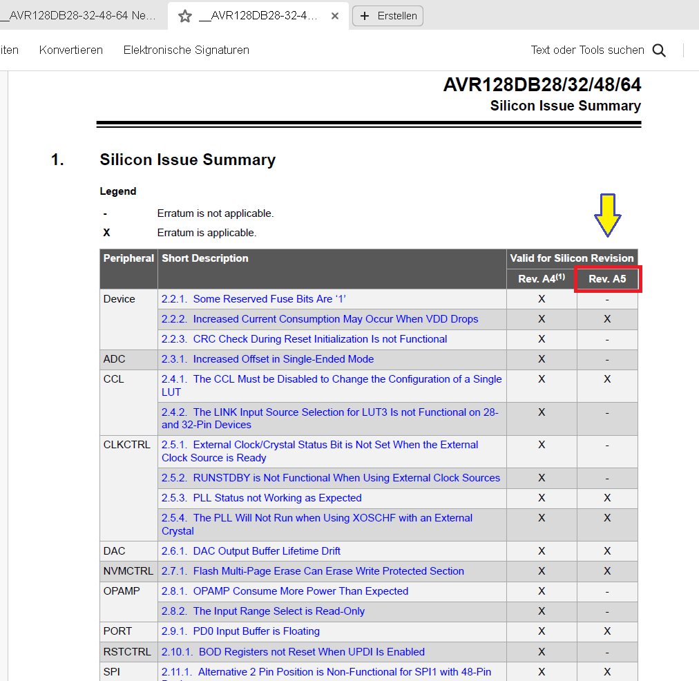
Silicon Issue Summary Tabelle AVR128DB28/32/48/64
AVR128DB28/32/48/64 Silicon Issue Summary Legend Erratum is not applicable. Erratum is applicable. Peripheral Short Description Valid for Silicon Revision Device 2.2.1. Some Reserved Fuse Bits Are '1' Rev
in „AVR128DA64 TCA1 funktioniert nicht mit alternativen Output?“ · Mikrocontroller und Digitale Elektronik · · Screenshots
-
Datei
adc_smalldemo.c
auf der seriellen Schnittstelle wieder aus. Genutzte Referenzspannung intern. MCU: ATmega8 / ATmega48 / ATmega88 / ATmega168 / ATmega328 Clock: intern RC oder extern Quarz Compiler: AVR-GCC 4.8.1 IDE: RSIDE Hardware: ADC1 hat einen vorgeschalteten Spannungsteiler 1M zu 220k (er- moeglicht Messungen groesser
in „Fragen zu meinem Batterietester“ · Mikrocontroller und Digitale Elektronik ·
-
Datei
max31865.c
/* * max31865.c * * Created: 13.9.2019 12:34:48 * Author : strakos.p */ // Includes #include "max31865.h" // Constant macro #define DDR(x) (*(&x - 1)) // address of data direction register of port x #if defined(__AVR_ATmega64__) || defined(__AVR_ATmega128
in „Probleme mit MAX31865, Wert zu klein“ · Mikrocontroller und Digitale Elektronik ·
-
Datei
avr910.asm
;CAN128 avr910-Devicecode not official! .db 0x23 ,0x10 ;tn2313 avr910-Devicecode not official! (STK500 Code used) .db 0x31 ,0x20 ;m48 avr910-Devicecode not official! .db 0x33 ,0x20 ;m88 avr910-Devicecode not
-
Datei
avr910.asm
;CAN128 avr910-Devicecode not official! .db 0x23 ,0x10 ;tn2313 avr910-Devicecode not official! (STK500 Code used) .db 0x31 ,0x20 ;m48 avr910-Devicecode not official! .db 0x33 ,0x20 ;m88 avr910-Devicecode not
-
Datei
dtmf_geb_m8a.asm
;*************************************************************************** ;* ;* Number : nach AVR314 ;* File Name : "dtmf_geb_m8a.asm" ;* Title : DTMF Generator ;* Datum : 16.02.2006 ;* Version : a ;* Target MCU : Any AVR with SRAM, 8 I/O pins and PWM ;* ;* This Application note describes how to
in „DTMF AVR314 nach mega8“ · Mikrocontroller und Digitale Elektronik ·
-
Datei
Code.txt
#define F_CPU 16000000UL #include <inttypes.h> #include <avr/io.h> //#include <util/delay.h> #include <avr/pgmspace.h> // global variables uint16_t pwm_plus_tabelle[16] PROGMEM = {0, 4, 8, 15, 19, 27, 35, 46, 58, 62, 79, 90, 100, 182, 216, 255}; uint16_t pwmtable
in „RGB Led mit PWM und 120Grad vesatz“ · Mikrocontroller und Digitale Elektronik ·
-
PDF
atmega_328.pdf
converter. These pins are powered from the analog supply and serve as 10-bit ADC channels. 4 8271BS–AVR–04/10 ATmega48A/48PA/88A/88PA/168A/168PA/328/328P 2. Overview The ATmega48A/48PA/88A/88PA/168A/168PA/328/328P is a low-power CMOS 8-bit microcon- troller based on the AVR enhanced RISC architecture.
in „1 Wire mit Atmega328“ · Mikrocontroller und Digitale Elektronik ·
-
Datei
bootload.lst
** 5 #define FLASHEND 0x03ff // Note: Word address 6 #define SRAM_START 0x0060 7 #define SRAM_SIZE 128 8 ; ***** BOOTLOADER DECLARATIONS ****************************************** 9 #define PAGESIZE 16 31 32 #define byte3(x) ((x)>>16) 33 #define byte2(x) ((x & 0xff00)>>8) 34 #define byte1(x) (x & 0xff) 35 36 37 /* 38 Atmel's AVR assembler is case insensitive, gcc is not. 39 mangled_case.h covers the cases where the representations in the 40 program mix case. 41 */ 42 #include "mangled_case.h" 1 /* 43 44 /* 45 This includes
in „Peter Danneggers Bootloader (fastboot) für AVR-GCC-Toolchain“ · Projekte & Code ·
-
PDF
nDDI0100E_ARM_ARM.pdf
ermöglichen Hardwaredesigns mit der Core (50 MIPs) mit Security JTAG Debug Port. Einfachheit der 8-bit AVR Familie zu realisieren. SAM7S: General Purpose USB MCUs von LQFP48 bis LQFP64, von 8K bis 256K Flash, sehr preisgünstig! Es sind keine zusätzlichen aktiven Bauelemente SAM7SE: SAM7S + Externes Bus SDRAM Interface, und komplexere PCB Layouts 256K bis 512K Flash im LQFP128 angekündigt für Q4 notwendig…platzieren Sie einfach 20 passive 05. Komponenten um den SAM7 und Sie können Ihr SAM7X: SAM7S + CAN + Ethernet MAC10/100 im LQFP100, 128K...256K Flash ARM Design in Betrieb
in „ARM was geht?“ · Mikrocontroller und Digitale Elektronik ·
-
Datei
lcdconpar.asm
, 0 , 252 , 0 , 0 , 0 , 0 .db 0 , 0 , 0 , 0 , 0 , 48 , 48 , 0 .db 6 , 12 , 24 , 48 , 96 , 192 , 128 , 0 .db 124 , 198 , 206 , 222 , 246 , 230 , 124 , 0 .db 48 , 112 , 48 , 48 , 48 , 48 , 252 , 0 .db 120 , 204 , 12 , 56 , 96 , 204 , 252 , 0 .db 120 , 204
in „LCD Controller für 640x480 LCD mit mega8515“ · Projekte & Code ·