US-Typen mit und ohne Schutzleiter (Typ A & B), aber auch schukokompatible (Typ C) und italienische (Typ L)).
Marktkauf der Edeka Minden in der Nähe hat: Da steht für die KW10 ab 02.03. ein 20W-PD-Ladegerät zu 4,79 €uro in der Werbung. Daneben stehen auch USB-Kabel zu akzeptablen Preisen.
Dietrich L. schrieb im Beitrag #8016286: > Bernd F. schrieb im Beitrag #8016025: >> Das Bild zeigt eine Uhr von mir. Elektrischer Aufzug, 6 Stunden >> Gang bis zum nächsten Aufzug. >> Das nützt dir natürlich
R. L. schrieb im Beitrag #8016636: > ich verwende für eine Uhr mit OCXO so eine Mini-USV als Netzteil: > > https://www.amazon.de/Unterbrechungsfreie-Stromversorgung-Mini-USV-Batterie-Backup-Kamera-Router-EU-Stecker
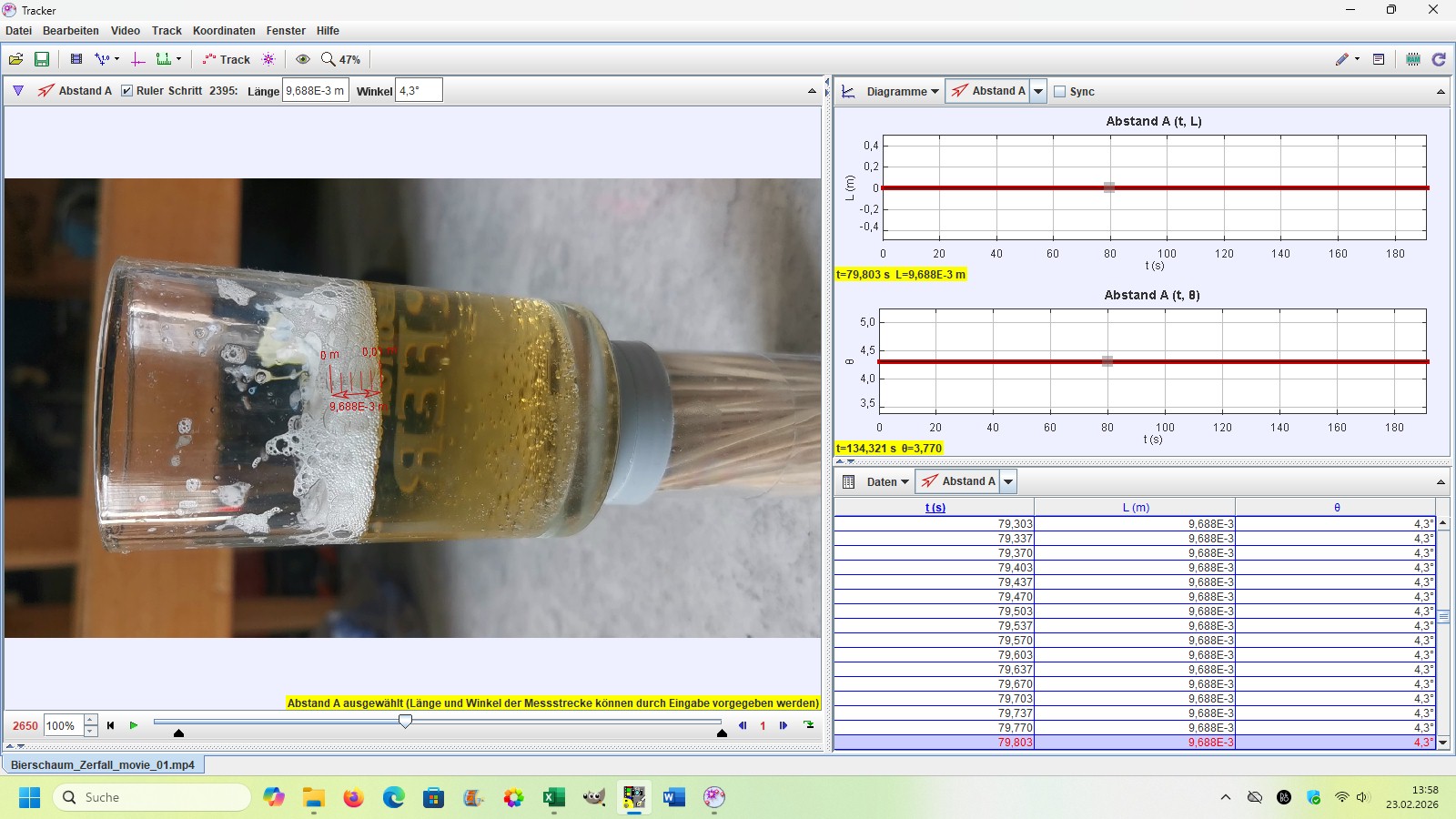
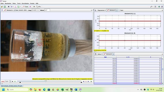
Bearbeiten Video Track Koordinaten Fenster Hilfe Abstand A Schritt 2395: Länge 9,688E-3 m Winkel 4,3° L (m) t (s) Abstand A (t, L) Abstand A (t, B) t=79,803 s L=9,688E-3 m t=134,321 s B=3,770 t (s) Daten Abstand A L (m) t (s) 79,303 9,688E-3 4,3° 79,337 9,688E-3 4,3° 79,370 9,688E-3 4,3° 79,437 9,688E-3 4,3° 79,470 9,688E-3 4,3° 79,537 9,688E-3 4,3° 79,570 9,688E-3 4,3° 79,637 9,688E-3 4,3° 79,703 9,688E-3 4,3° 79,737 9,688E-3 4,3° 79,770 9,688E-3 4,3° 79,803 9,688E-3 4,3° Bierschaum_Zerfall_movie_01.mp4
configurations 4 Pin configurations I A X G M D R P S B _ P E 2 W O P O E P R P I N S C # V W V V L V I [ O S [ E _ [ # # # G C P E C C ] R K ] L D ] [ [ [ N _ W G C S / 1 / / 7 A / ] ] ] G D R 4 4 4 4 4 4 4 4 4 3 3 3 8 7 6 5 4 3 2 1 0 9 8 7 AMBER[2] / SPI_MOSI / VCC_A 1 36 PWR_PIN_POL GREEN[2] / GND
Gleichrichtern bzw. Reglern > messen. 100V am Ausgang des Endstufengleichrichters V1 +12V Ausgang L7812 -12V Ausgang L7912 > - Verbindung Coll. V9 zu C74/R81 auftrennen. Einschalten mit vorest > abgeklemmten LS, nach ein paar Sekunden LS wieder anschließen, hören & > berichten. Mit getrennter
Schaltungstechnik, die ist ziemlich "rudimentär". Einfach mal die Prinzipschaltbilder von 78xx mit 79xx vergleichen. Aber ich bin ja neugierig. Zeig doch mal wie du da DREI Bypass-Dioden verbaust und erzähle welchen Ströme sie ableiten, bzw. wie diese Zustandekommen! Danke
21,43) (2,36) 9 8 As 2 Required 0 .016 .002 .250 0 (0,41 0,05) (6,35) ( .938 a (Max.1) r .328 .031 l (8,33 0,79) (1,02) or (1,27) c (11,11) Dia. Dia. o 8000-AG36 Max. (2,13 0,25) e Horizontal .750 i Printed Circuit (3,18) (19,05) (5,95) t Mounting Min. u .500 0 .055 .400 (12,70) 2 (1,40) (10,16) - Dia
Grille de prix de l’offre de fourniture d’électricité « Tarif Bleu » er Applicable au 1 février 2026 OFFRE POUR LES CLIENTS PARTICULIERS L’offre « Tarif Bleu » porte sur la fourniture d’électricité et sur l’accès et l’utilisation
9. AC testing load circuit 5V 1.8kΩ DEVICE UNDER OUT TEST 1kΩ C = 100pF L C includes JIG capacitance L AI01019 Table 7. Capacitance Symbol Parameter (1)(2) Min Max Unit C IN Input capacitance - 10 pF C (3) Input / output capacitance - 10 pF IO 1. Effective capacitance measured
23000 kWh Energiebedarf via > Ölheizung. ????????? 23000 kWh -----> das wären ja weniger als 2000l Heizöl!
Energiebedarf via >> Ölheizung. > > ????????? > 23000 kWh -----> das wären ja weniger als 2000l Heizöl! Falls Du google o.ä. bedienen kannst, such mal nach Brenn-/Heizwert für Heizöl oder Diesel.
±.010 .110 ±.010 mounted to or a metal clip in contact with the top (2.39 ±.10).DIA(8.12 ±.26) (2.79 ±.26) surface of the part. L + .440 ±.010 Insulation Resistance: 10,000 Megohms min. (11.18 ±.26) The resistor element is electrically isolated from (2.03 ±.51) M0.10Ω (2.92 ±.26) the mounting surface
HCS361 ® K EE L OQ Code Hopping Encoder FEATURES DESCRIPTION Security The HCS361 is a code hopping encoder designed for • Programmable 28/32-bit serial number secure Remote Keyless Entry (RKE) systems. The • Programmable
l b (1) Reserved. n 2 c d 1 o Fig 10. UART write data timing diagram a 6 g d d p l Remark: The data byte can be sent directly after the address byte on pin RX. e m f s o . Address byte: The address byte
ProductDetail/STMicroelectronics/X0402MF-1AA2?qs=6z1DzwtmQLDSJnCMtOTL5w%3D%3D&srsltid=AfmBOooxPp_4CAbpv79FlsSjHWwuZ4ta52fAlDqNzlCkThTmvx4BlJsT Ich hatte gerade geschaut. Den gibt's wohl so nicht mehr und dafür ist ein Ersatztyp angegeben. Die Werte sollten auch ungefähr stimmen. Wenn sonst nichts kaputt
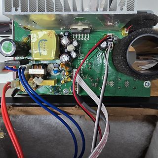
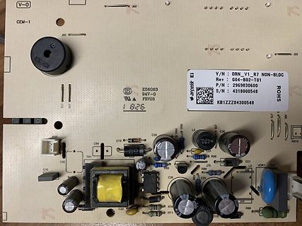
Wenn ich es richtig verstanden habe gibt es geschaltete 230V AC mit L und N sowie 2 Adern zum Ventil. Keine weitere Leitung zur Steuerung. Also 230V an => Ventil an. 230V aus => Ventil aus. Funktion der Leiterplatte ? Daher meine Vermutung oben. Ein Bild von der
DB3 DB2 DB1 DB0 R L7 L6 L5 L4 L3 L2 L1 L0 0 C6 C5 C4 C3 C2 C1 C0 0 Figure 5 Status Read Instruction Start Oscillation (R00h) The start oscillation instruction restarts the oscillator from the halt state in the stanAfterode
Rückseite) bis 169€ (Display) und 189€ (Hauptkamera). Beim Samsung A06 kostet die Reparatur vom Display 79€. Letztlich geht es bei den EU Regelungen wesentlich darum, dass solche Reparaturen zu vertretbaren Preisen möglich sind. Nicht nur bei Mobilgeräten. Und wenn sich beim Kauf eines Gerätes andeutet
erreichte was natürlich die Tagestauglichkeit herabsetzte. Noch ärgerlicher bei einem alten BMW 750iL, da gab es nach 10 Jahren auch für Geld und gute Worte keine Ersatzxenonscheinwerfer, Abhilfe auf Halogen zurückrüsten.
or A = +50⋅C N E I N ) 70 Free Air 3.0 A T C Mounted I I ( I E I 60 Vertically 2.0 oz. Copper 2.5 D L ▯ L R A T ÎÎÎÎ W R N Minimum O H I 50 ÎÎÎÎ 2.0 P , C Size Pad L U J U ÎÎÎÎ I θ J 40 1.5 A R ÎÎÎÎ , RθJA PD 30 1.0 0 5.0 10 15 20 25 30 L, LENGTH OF COPPER (mm) 2 Figure 19. D PAK Thermal Resistance and
Ammopack: [mm] P 2 1 W H H 1 W 0 W W T d P1 F D0 T1 P0 I H Strap Cover Feeding direction Cover Tape L IC IC W min. 3 grid spaces Components min. 3 grid spaces No Component No Component Packaging is referred to the international standard IEC 60286-2:2015 Packaging P P0 P1 F H H1 d T T1 = d + T W W0 W1
vs. Input Input Voltage, 5.0 V Version Voltage, 3.3 V Version 6.0 6.0 T = 25°C V 5.0 V 5.0 J E ( R L= 20 W G R = 20 W E T 4.0 L A 4.0 L TJ= 25°C L V O T 3.0 V 3.0 U U T P U 2.0 U 2.0 , O Q ,Q V 1.0 V 1.0 0 0 0 2.0 4.0 6.0 8.0 10 0 1.0 2.0 3.0 4.0 5.0 6.0 V I INPUT VOLTAGE (V) VI, INPUT VOLTAGE (V) Figure
The LED stays on (instead of blinking) if the initial temperature display on the LCD is greater than 79°F. 4. Press SW1 or SW2 to calibrate the temperature sensor offset, to display a known temperature reading in your area. 5. Initially, pressing SW1 or SW2 adjusts the second digit after the decimal. 6
: - - LC-Display 1 r 0 LCD1 4 1 m o 5 o o d r f S C F Power i g m L B o o n Prog r K o p t Standby e n a d r ts a t l b ö i e L t i a m h c Standby Power C/F S O O O O C C C C 6 5 4 3 2 1 0 9 8 7 6 5 4 3 2 1 0 9 8 7 6 5 4 3 2 1 0 9 8 7 6 5 4 3 2 1 3 3 3 3 3 3 3 2 2 2
BCompensation FrequencyAdjust R340 A MSB R252 B MSB R245 Digital Audio Board A3 Generator PLL Freq Adjustment L1 Frequency Offset Frequency Adjustment L5 Frequency Offset Frequency Adjustment L7 Eye Sampler Frequency Adjustment L16 GeneratorLevel R483 GeneratorBoard A5 A DAC Gain (Left) R24 B DAC Gain (Right)
- At 230 VAC 40 A max. - At 115 VAC 25 A max. Input Protection T 1.6 A / 250 VAC (Internal Fuse in L & N) Recommended Input Fuse (The need of an external fuse has to be assessed in the final application.) Output Specifications Output Voltage Adjustment ±10% (By external trim resistor) See application

 Bild
Bild
 Bild
Bild
 Bild
Bild
 Bild
Bild
 Bild
Bild