deutlich mehrfach pro Sekunde, ich schätze ca. 4x/s. Interessant: es zeigt "alle" Werte an, nur nicht "51". Wenn ich beschleunige (ich hab ein Video gemacht) zählt es gleichmäßig von 0 bis 105 hoch (schneller konnte ich nicht), nur auf die 50 folgt 52. Die Schaltung ist auch schräg: je zwei grüne LEDs
Jens M. schrieb im Beitrag #8021493: > "Nur" alle 200ms ist wesentlich schneller als bei GPS üblich ist (dort > normalerweise 1/s, das reicht für Navigation, Geschwindigkeit fällt > nebenbei ab), und sofern man nicht extrem bremst oder beschleunigt > sollte
and backwards communication of [47]. The filter function in the old schematic repres- takes about 12ms. ents akeystreambit atthepreviousstate f(x i−1 ...xi+46), while the one in Figure 11 represents a keystream bit of the current state f(x ...x ). Furthermore, we have { 11000001111100000111 } i i+47 −
diszipliniert zu planen and programmieren. Viele Realwelt Steuer Anwendungen agieren mit ihrer Umwelt in ms oder s Skala. Und wenn es wirklich nicht langt, skaliert man aufwärts. Für "moderne" kommunizierenden Anwendungen nimmt man ohnehin oft ESP32 oder Vergleichbares. Gerhard
Derivate, die sich über UART Flashen lassen. Und auch nur, weil mir einige zugelaufen sind und der Keil MC51 kompatibel ist. Ob es sich lohnt viel Zeit zu investieren - da bin ich eher skeptisch. Aber es wäre eine Gelegenheit die Tochter einer anderen Mutter näher kennenzulernen. Seid froh, dass es für
pin count.Theindividualorgangmode isdecided within20µsafterpoweronreset.It hasa setuptime of 1ns. 50 ms to 60 ms after reset,this pin is changed to output mode.CY7C65642 outputsthesuspendflag,once itis globallysuspended.Pull-downresistorofgreaterthan100KisneededforIndividualmodeandapull-upresistor greater
Component Program of devices made to JEDEC placement on the pc board k A Underwriters Specifications MS-018 footprint pattern facilitates s , Laboratories Inc., ® (square packages) and MS- inspection as well as c 016-AE (rectangular permitting the heat source c File No. E28476 packages). to penetrate to
ILED= 80 mA 440 TF LED fall time ILED= 175 mA 360 ns ILED= 80 mA 320 TLO EN/PWM low time 1 ms T HI EN/PWM high time 5 ms T PWRDWN EN/PWM low time to shutdown delay 4 8 ms THI TPWRDWN TLO EN/PWM SHUTDOWN POWERDOWN SHUTDOWN 0 mA TP2 T 1.2 V F ILED+ 100 T PS TP1 TR RSET 90% LED CURRENT 50% 50% 10%
Symb Typ Min Max Typ Min Max A 3.05 0.120 A1 0.05 0.36 0.002 0.014 A2 2.34 2.69 0.092 0.106 B 0.36 0.51 0.014 0.020 C 0.15 0.32 0.006 0.012 D 17.71 18.49 0.697 0.728 E 8.23 8.89 0.324 0.350 e 1.27 – – 0.050 – – eB 3.20 3.61 0.126 0.142 H 11.51 12.70 0.453 0.500 L 0.41 1.27 0.016 0.050 a 0° 8° 0° 8° N 28
MS3x ;Kein Überlauf ldi AH, 0 sts PWM5, AH sts PWM3, AL ;Übertrag com AL sts PWM4, AL ldi AL, LOW(MS4) sts PWMAdrl, AL ldi AL, HIGH(MS4) sts PWMAdrh, AL ret MS32: ;rechts rum sbc AL, AH brcc MS3x ;Kein
All other pins to AGND.................. -0.3V to 6.5V operating conditions. (2) 4) Measured on JESD51-7, 4-layer PCB. Continuous power dissipation (T = +25° A C) QFN-28 (4mmx4mm)……………………2.9W Storage temperature................-55C to +150C Junction temperature.............................+150C Lead
REQUIREMENTS VDD = 5.0V ±10% 25° C ±5 °C Parameter Symbol Min. Max. Units Program mode setup time T2 0 4.0 ms Hold time 1 T1 9.0 — ms Program cycle time TWC 50 — ms Clock low time TCLKL 50 — μs Clock high time TCLKH 50 — μs (1) Data setup time TDS 0 — μs Data hold time TDH 30 — μs(1) Data out valid time TDV
page 50 and TX2 15h TxASKReg controls the setting of the transmission modulation Table 63 on page 51 16h TxSelReg selects the internal sources for the antenna driver Table 65 on page 51 17h RxSelReg selects internal receiver settings Table 67 on page 52 18h RxThresholdReg selects thresholds for the
weiterhin außer Betrieb. Bezeichnung Detektionszeit Sicherheitsschaltung FST- Elektr./mech. Schaltung 10 ms 2XTs Schütz für Bremse/Ventile Siemens 3RTxxx 12 ms Zonenmagnetschalter Schmersal BN32r Schaltzeit Schließer 0,3 – 1,5 ms Wiederanfahrgenauigkeit +/- 0,25 mm Geschwindigkeitssignal FST-2XT 102 ms >0,2 ms Geschwindigkeitssignal Frequenzumrichter 15 ms >0,2 ms Seite 5 von 9 Anhang zur EU-Baumusterprüfbescheinigung Nr. EU-ESD 024 vom 04.10.2016 Die genannten Typen der „Schütze für Bremse/Ventile“ sowie
10 divisions Posttrigger delay (from trigger point to start of sweep) at least 2560 divisions or 50 ms. Not to exceed 100 s. Delayed sweep operation Main sweep Delayed sweep 5 s/div to 10 ms/div up to 200 times main sweep 5 ms/div and faster up to 2 ns/div 1Use full scale of 50 ns on 2 ns/div range. 2
automatically reinitialized when the HD66766R is reset. The reset input must be held for at least 200 ms. Do not access the GRAM or initially set the instructions until the R-C oscillation frequency is stable after power has been supplied (10 ms). Instruction Set Initialization: 1. Start oscillation executed
StockService DIRECTION OF ROTATION Drehrichtung f 31 T 170,5 51 16 ) H 22 ( P 19 2 2 i 16 , D - ) H i 2 5 4 P / 5 E T 2 5 × E 1 , ( 5 2 M 0 ) 1 , 0( 27° h 7 + 3 45° 18° PLUG CONNECTOR 2.8×0,5 DC Motor 31 x 51 Flachstecker 1.13.021.3XX ■ Type / Baureihe 1.13.021.XXX
im Beitrag #7993290: > Warum muss man das? Weil es da https://library.e.abb.com/public/edc51e83d85231d8c1257845002a4a8f/2CDC400027D0101.pdf drin steht und ansonsten nicht 'fachmännisch' wäre. Es interessiert nicht, was DU denkst. Überlasse das Denken denjenigen, die sich damit auskennen
SharedDocs/pdf/DE/Unfallberichte/2018/Anhaenge/Gutachten_455_15_und_58_16.pdf Untersuchungsbericht Fall "MS Katrina" in der Elbmündung 20Nov2015 und "LUDWIGSHAFEN EXPRESS" im Roten Meer am 21Feb2016: https://www.bsu-bund.de/SharedDocs/pdf/DE/Unfallberichte/2018/Untersuchungsbericht_455_15_und_58_16.pdf
Carrier Sense Carrier Sense (CRS) is asserted in half-duplex switching cycle time is located from 200ms to 420ms. The polarity control is always switch until detect operation during transmission or reception of data. received signal. After selected MDI or MDIX, During full-duplex mode, CRS is asserted
failure mode is L short from over-specified • Meet MSL level1, per Peak Forward Surge Current, 8.3ms voltage or current J-STD-020, LF maximun Single Half Sine Wave (Note 3) IFSM 200 A peak of 260 °C • Whisker test is conducted Maximum Instantaneous Forward based on JEDEC • Matte tin lead–free plated
rated V-0 per Infinite Heat Sink aLT75ºC Underwriters Laboratories Peak Forward Surge Current, 8.3ms JESD201A per its table 4a Single Half SineWave Unidirectional I 200 A and 4c • Matte tin lead–free plated FSM Only (Note 2) • IEC-61000-4-2 ESD • Halogen free and RoHS Maximum Instantaneous Forward 30kV
built-in pull-up resistor 46 DIR2 Output Used to control RS485 receiving/transmitting switch of UART2 51 DIR1 Output Used to control RS485 receiving/transmitting switch of UART1 52 ACT# Output Ethernet connection communication indicator LED drive pin 53 LINK# Output PHY connection indicator LED, active
kostet da auch extra, bei der Telekom ist das schon mit drin für 5,- € mehr monatl. zu 45,-€ ggn.über 51,- € bei der DGN.
Euro zusätzlich und die MF-Flat noch mal 7 €, macht zusammen 11 Euro zu den 40 €, dann sind wir bei 51,- Euro zu 46,-€ der Telekom, womit uns unsere liebe Stadtverwaltung verkauft oder verarscht hat. Dass man bei der DGN für mehr Geld auch noch was Vernünftiges bekommt habe ich schon im AGFEO-FH-Forum
.79732/ Und von den uralten MCS-51 ist da die Rede. > und dann gibt es noch einen avrdude. (software) Die kann nicht zaubern.
ich Dir einen Link für den Upload zu mir. Einstellungen für den LA: Wenn der LA problemlos mit 24MS/s läuft, gerne so lassen. Ansonsten die Abtastrate verkleinern. 2MS/s sollten zwar auch gerade noch reichen, mehr zeitliche Auflösung wäre aber dennoch schön. Abtastrate kann im Menu am rechten Rand
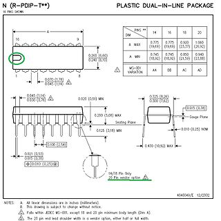
mm dimensions) A A 1 A2 (1) (1) Z (1) UNIT max. min. max. b b1 c D E e e1 L M E MH w max. mm 4.2 0.51 3.2 1.73 0.53 0.36 26.92 6.40 2.54 7.62 3.60 8.25 10.0 0.254 2.0 1.30 0.38 0.23 26.54 6.22 3.05 7.80 8.3 inches 0.17 0.020 0.13 0.068 0.021 0.014 1.060 0.25 0.10 0.30 0.14 0.32 0.39 0.01 0.078 0.051
26,635 48 37/2005 national BRD 26,645 49 37/2005 national BRD 26,655 50 37/2005 national BRD 26,665 51 37/2005 national BRD 26,675 52 37/2005 national BRD 26,685 53 37/2005 national BRD 26,695 54 37/2005 national BRD 26,705 55 37/2005 national BRD 26,715 56 37/2005 national BRD 26,725 57 37/2005 national
| 2446 - 2454 500 mW (EIRP) 4 W (EIRP) nur innerhalb geschlossener Gebäude, Belegungsdauer max. 30 ms je 200 ms, frequency hopping spread spectrum 865,0 - 865,6 100 mW (ERP) listen-before-talk (LBT), kein spread spectrum, 200 kHz Raster (Kanäle 1-3) 865,6 - 867,6 2 W (ERP) LBT (außer 865,7, 866,3, 866,9

 Bild
Bild
 Bild
Bild
 Bild
Bild
 Bild
Bild
 Bild
Bild
 Bild
Bild
 Bild
Bild

 Bild
Bild