
-
PDF
Hargassner_Datenprotokoll_155_Pakete.pdf
Schieberostposition ist 72 /'72/' name=/'SR mode/' unit=/'/'//> \ **** Schieberost Modus 73 /'73/' name=/'KaskSollTmp_1/' unit=/'°C/'//> **** Kaskade Soll Temperatur 1 74 /'74/' name=/'KaskSollTmp_2/' unit=/'°C/'//> **** Kaskade Soll Temperatur 2 75 /'75/' name=/'KaskSollTmp_3/' unit=/'°C/'//> \ **** Kaskade Soll Temperatur 3 76 /'76/' name=/'KaskSollTmp_4/' unit=/'°C/'//> **** Kaskade Soll Temperatur 4 77 /'77/' name=/'KaskIstTmp_1/' unit=/'°C/'//> **** Kaskade Ist Temperatur 1 78 /'78/' name=/'KaskIstTmp_2/' unit=/'°C/'//> \ **** Kaskade Ist Temperatur
in „Hargassner Pelletheizung Betriebsdatenerfassung“ · Haus & Smart Home ·
-
PDF
Hargassner_Datenprotokoll_155_Pakete.pdf
Schieberostposition ist 72 /'72/' name=/'SR mode/' unit=/'/'//> \ **** Schieberost Modus 73 /'73/' name=/'KaskSollTmp_1/' unit=/'°C/'//> **** Kaskade Soll Temperatur 1 74 /'74/' name=/'KaskSollTmp_2/' unit=/'°C/'//> **** Kaskade Soll Temperatur 2 75 /'75/' name=/'KaskSollTmp_3/' unit=/'°C/'//> \ **** Kaskade Soll Temperatur 3 76 /'76/' name=/'KaskSollTmp_4/' unit=/'°C/'//> **** Kaskade Soll Temperatur 4 77 /'77/' name=/'KaskIstTmp_1/' unit=/'°C/'//> **** Kaskade Ist Temperatur 1 78 /'78/' name=/'KaskIstTmp_2/' unit=/'°C/'//> \ **** Kaskade Ist Temperatur
in „Hargassner / Rennergy Touchtronic Netzwerkanbindung/Visualisierung“ · Haus & Smart Home ·
-
Datei
Empfaenger.c
/* * CAN1.c * * Created: 26.01.2012 18:48:36 * Author: stormracer */ //#define F_CPU 16000000UL #define BAUDRATE 9600 #include <stdbool.h> #include <stdlib.h> #include <stdio.h> #include <avr/io.h> #include <avr/interrupt.h> #include <util/delay.h
in „CAN BUS empfängt nichts“ · Mikrocontroller und Digitale Elektronik ·
-
Datei
part-db.diff
, 5.11, 5.17, 5.23, 5.3, 5.36, 5.42, 5.49, 5.56, 5.62, 5.69, 5.76, 5.83, 5.9, 5.97, 6.04, 6.12, 6.19, 6.26, 6.34, 6.42, 6.49, 6.57, 6.65, 6.73, 6.81, 6.9, 6.98, 7.06, 7.15, 7.23, 7.32, 7.41, 7.5, 7.59, 7.68, 7.77, 7.87, 7.96, 8.06
in „PART-DB RW 1.2“ · Projekte & Code ·
-
Datei
UHR120_4.ASM
* INT0 (DCF-Signal) bearbeiten **************************************************** impuls: in isr_tmp,sreg ;Flagreg.sichern cpi testhl,114 ;912ms brcs igno ;wenn kleiner -> igno clr testhl ;Timerreg=0 inc sek ;DCF-sek + 1 igno: out sreg,isr_tmp ;Flag's zurückschreiben reti ;****** TOVO bearbeiten **
in „AT90S1200 Programm auf AT90S8515 umschreiben“ · Mikrocontroller und Digitale Elektronik ·
-
Datei
UHR120_8.ASM
* INT0 (DCF-Signal) bearbeiten **************************************************** impuls: in isr_tmp,sreg ;Flagreg.sichern cpi testhl,114 ;912ms brcs igno ;wenn kleiner -> igno clr testhl ;Timerreg=0 inc sek ;DCF-sek + 1 igno: out sreg,isr_tmp ;Flag's zurückschreiben reti ;****** TOVO bearbeiten **
in „ACHTUNG MIT AT90S1200 UND yaap!!!!!!!“ · Mikrocontroller und Digitale Elektronik ·
-
Datei
UHR120_8.ASM
* INT0 (DCF-Signal) bearbeiten **************************************************** impuls: in isr_tmp,sreg ;Flagreg.sichern cpi testhl,114 ;912ms brcs igno ;wenn kleiner -> igno clr testhl ;Timerreg=0 inc sek ;DCF-sek + 1 igno: out sreg,isr_tmp ;Flag's zurückschreiben reti ;****** TOVO bearbeiten **
in „ACHTUNG MIT AT90S1200 UND yaap!!!!!!!“ · Mikrocontroller und Digitale Elektronik ·
-
Datei
Wand.c
= pwm_setting_tmp[i]; pwm_setting_tmp[i] = tmp_set; tmp_mask = main_ptr_mask[k]; main_ptr_mask[k] = main_ptr_mask[i]; main_ptr_mask[i] = tmp_mask; } } // Gleiche PWM-Werte vereinigen, ebenso den PWM-Wert 0 löschen falls
in „Mega8 an Schaltnetzteil geht nicht“ · Mikrocontroller und Digitale Elektronik ·
-
Datei
main.c
Timer 1 Output COMPARE A Interrupt /** ISR(TIMER1_COMPA_vect) { static uint8_t pwm_cnt=0; uint8_t tmp=0; OCR1A += (uint16_t)T_PWM; if (pwm_setting[0] > pwm_cnt) tmp |= (1<<0); if (pwm_setting[1] > pwm_cnt) tmp |= (1<<1); if (pwm_setting[2] > pwm_cnt) tmp |= (1<<2); if (pwm_setting[3] > pwm_cnt) tmp |= (1<<3); if (pwm_setting[4] > pwm_cnt) tmp |= (1<<4); if (pwm_setting[5] > pwm_cnt) tmp |= (1<<5); if (pwm_setting[6] > pwm_cnt) tmp |= (1<<6); if (pwm_setting[7] > pwm_cnt) tmp |= (1<<7); PWM_PORT = (tmp<<1); // PWMs aktualisieren if (pwm_cnt
in „Master und 3 Slaves, Kommunikation läuft nicht rund Bitte um Hilfe“ · Mikrocontroller und Digitale Elektronik ·
-
Datei
Uh2313_8.asm
* INT0 (DCF-Signal) bearbeiten **************************************************** impuls: in isr_tmp,sreg ;Flagreg.sichern cpi testhl,114 ;912ms (zwischen 2 Flanken ist 1 sek) brcs igno ;wenn kleiner -> igno(Fehler unterdrücken) clr testhl ;Timerreg=0 inc sek ;DCF-sek + 1 igno: out sreg,isr_tmp ;Flag's
-
Datei
rfm70.c
payload len writeRegVal(RFM70_CMD_WRITE_REG | (RFM70_REG_RX_PW_P0 + nr), plLen); // set EN_AA bit tmp = readRegVal(RFM70_REG_EN_AA); if (en_aa) tmp |= 1 << nr; else tmp &= ~(1 << nr); writeRegVal(RFM70_CMD_WRITE_REG | RFM70_REG_EN_AA, tmp); // clear DPL bit tmp = readRegVal(RFM70_REG_DYNPD); tmp &=
in „RFM70 Timing Problem?“ · Mikrocontroller und Digitale Elektronik ·
-
Datei
pegasus_5x7_font.bas
H45, &H45, &H39 '5 Data &H3C, &H4A, &H49, &H49, &H30 '6 Data &H01, &H71, &H09, &H05, &H03 '7 Data &H36, &H49, &H49, &H49, &H36 '8 Data &H06, &H49, &H49, &H29, &H1E '9 Data &H00, &H36, &H36, &H00, &H00 ': Data &H00, &H56, &H36, &H00, &H00 '; Data &H00, &H08, &H14, &H22, &H41 '< Data &H14, &H14, &H14, &
in „Mini-Farbdisplay (+mehr) für 1 Euro“ · Mikrocontroller und Digitale Elektronik ·
-
Datei
fading_v1b.c
nop"); } speed_tmp1 = speed_tmp1 - 4; // Bei Tastendruck Umlaufzeit if(speed_tmp1 == 0){ // verkürzen speed_tmp1 = 100; } } lauflicht(0,speed_tmp1,0,3); } if(mode == 4 && second < sec_tmp + 5){ mode = 4;} else if(mode
in „Fading Funkuhr“ · Mikrocontroller und Digitale Elektronik ·
-
 Bild
Bild
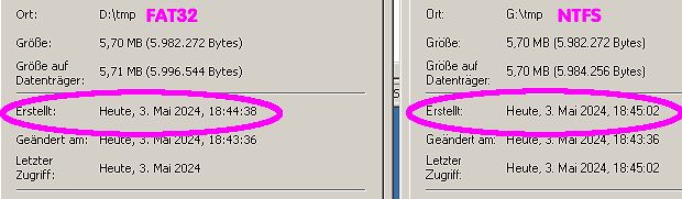
Vergleich von Dateieigenschaften FAT32 und NTFS
Ort: D:\tmp FAT32 Größe: 5,70 MB (5.982.272 Bytes) Größe auf Datenträger: 5,71 MB (5.996.544 Bytes) Erstellt: Heute, 3. Mai 2024, 18:44:38 Geändert am: Heute, 3. Mai 2024, 18:43:36 Letzter Zugriff: Heute, 3. Mai 2024 Ort: G:\tmp NTFS Größe: 5,70 MB (5.982.272 Bytes) Größe auf Datenträger: 5,70 MB (5.984.256 Bytes) Erstellt: Heute, 3. Mai 2024, 18:45:02 Geändert am: Heute, 3. Mai 2024, 18:43:36 Letzter Zugriff: Heute, 3. Mai
in „SD Card auf PC kopieren, Datum ändert sich“ · PC Hard- und Software · · Screenshots
-
Datei
prog.s
prologue: function */ /* frame size = 0 */ .LM2: call dummy ; .LM3: sbi 55-32,6 ; ,, .LBB34: .LBB35: .LBB36: .LBB37: .LM4: ldi r25,lo8(26) ; tmp59, .L2: .LBE37: .LBE36: .LBE35: .LBE34: .LM5: sbi 56-32,6 ; ,, .LBB41: .LBB40: .LBB39: .LBB38: .LM6: mov r24,r25 ; __count, tmp59 .LVL0: /* #APP */ ; 83 "c:/winavr
in „Problem beim Auslagern von Funktionen“ · Mikrocontroller und Digitale Elektronik ·
-
Datei
led.c
if (TmrCounter++ ==3) { // 16us * 4 = 64us if( ++rc5_time > PULSE_MAX ){ // count pulse time if( !(tmp & 0x4000) && tmp & 0x2000 ) // only if 14 bits received rc5_data = tmp; tmp = 0; } if( (rc5_bit ^ RC5_IN) & 1<<RC5 ){ // change detect rc5_bit = ~rc5_bit; // 0x00 -> 0xFF -> 0x00 if( rc5_time < PULSE_MIN ) // to short tmp = 0; if( !tmp || rc5_time > PULSE_1_2 ){ // start or long pulse time if( !(tmp & 0x4000) ) // not to many bits tmp <<= 1; // shift if( !(rc5_bit & 1<<RC5) ) // inverted bit tmp |= 1; // insert new bit
in „Steuerung LED Zimmerbeleuchtung 4-Kanal“ · Projekte & Code ·
-
Datei
led.c
if (TmrCounter++ ==3) { // 16us * 4 = 64us if( ++rc5_time > PULSE_MAX ){ // count pulse time if( !(tmp & 0x4000) && tmp & 0x2000 ) // only if 14 bits received rc5_data = tmp; tmp = 0; } if( (rc5_bit ^ RC5_IN) & 1<<RC5 ){ // change detect rc5_bit = ~rc5_bit; // 0x00 -> 0xFF -> 0x00 if( rc5_time < PULSE_MIN ) // to short tmp = 0; if( !tmp || rc5_time > PULSE_1_2 ){ // start or long pulse time if( !(tmp & 0x4000) ) // not to many bits tmp <<= 1; // shift if( !(rc5_bit & 1<<RC5) ) // inverted bit tmp |= 1; // insert new bit
in „Steuerung LED Zimmerbeleuchtung 4-Kanal“ · Projekte & Code ·
-
Datei
DCF4.asm
* INT0 (DCF-Signal) bearbeiten **************************************************** impuls: in isr_tmp,sreg ;Flagreg.sichern cpi testhl,114 ;912ms brcs igno ;wenn kleiner -> igno clr testhl ;Timerreg=0 inc sek ;DCF-sek + 1 igno: out sreg,isr_tmp ;Flag's zurückschreiben reti ;****** TOVO bearbeiten **
in „DCF-Uhr auf LCD mit AVR Control“ · Mikrocontroller und Digitale Elektronik ·
-
Datei
log.txt
atmega128' '-I' '/home/georg/gnu/install/gcc-4.7/avr/include' '-v' '-save-temps' '-fltrans-output-list=/tmp/ccv4pe15.ltrans.out' '-fwpa' '-fresolution=980709-1.res' [Leaving LTRANS /tmp/ccUyHaS1.args] [Leaving LTRANS /tmp/ccv4pe15.ltrans.out] /mnt/nfs/home/georg/gnu/install/gcc-4.7/bin/avr-gcc @/tmp/cckh0j2T.args
in „avr-libc: relocation truncated to fit“ · Mikrocontroller und Digitale Elektronik ·
-
Datei
RFM_02_test_V7.bas
Temp As Byte Dim Cmd(2) As Byte Declare Sub Fsk_send(byval Fsk_byte As Byte) Declare Sub Rf_cmd(byval Tmp As Word) As Word 'config SPI Config Spi = Hard , Interrupt = Off , Data Order = Msb , Master = Yes , Polarity = Low , Phase = 0 , Clockrate = 16 , Noss = 0 'Config Spi = Soft , Din = Pinb.4 , Dout =
-
Datei
test2.c
2, 2, 2, 2, 2, 3, 3, 3, 4, 4, 5, 5, 6, 6, 7, 8, 9, 10, 11, 12, 13, 15, 17, 19, 21, 23, 26, 29, 32, 36, 40, 44, 49, 55, 61, 68, 76, 85, 94, 105, 117, 131, 146, 162, 181, 202, 225, 250, 279, 311, 346, 386, 430, 479, 534, 595, 663, 739, 824, 918, 1022}; // Timer 1 Output COMPARE A Interrupt ISR(TIMER1_COMPA_vect) { static uint16_t pwm_cnt=0; uint8_t tmp=0; if (pwm_setting[0] > pwm_cnt) tmp |= (1<<0); if (pwm_setting[1] > pwm_cnt) tmp |= (1<<2); if (pwm_setting[2] > pwm_cnt) tmp |= (1<<3); PWM_PORT = tmp; // PWMs aktualisieren if (pwm_cnt==(uint16_t
in „Moodlight Sourcecode hilfe“ · Mikrocontroller und Digitale Elektronik ·
-
Datei
RFM_02_868_neu.bas
Temp As Byte Dim Cmd(2) As Byte Declare Sub Fsk_send(byval Fsk_byte As Byte) Declare Sub Rf_cmd(byval Tmp As Word) As Word 'config SPI Config Spi = Hard , Interrupt = Off , Data Order = Msb , Master = Yes , Polarity = Low , Phase = 0 , Clockrate = 16 , Noss = 0 'Config Spi = Soft , Din = Pinb.4 , Dout =
-
Datei
RFM_02_868_neu.bas
Temp As Byte Dim Cmd(2) As Byte Declare Sub Fsk_send(byval Fsk_byte As Byte) Declare Sub Rf_cmd(byval Tmp As Word) As Word 'config SPI Config Spi = Hard , Interrupt = Off , Data Order = Msb , Master = Yes , Polarity = Low , Phase = 0 , Clockrate = 16 , Noss = 0 'Config Spi = Soft , Din = Pinb.4 , Dout =
-
Datei
ir.c
wurde // Returns 32Bit Code of pressed key or zero otherwise. uint32_t ir_getkeypress(void) { uint32_t tmp = pressedkey; pressedkey = 0; return tmp; } ////////////////////////////////////////////////////////////////////////// // Reset Hash static inline void hash_reset(void) { CRC_ResetDR(); } //////////
in „Universeller IR-Receiver für viele Protokolle“ · Projekte & Code ·
-
Datei
ir.c
wurde // Returns 32Bit Code of pressed key or zero otherwise. uint32_t ir_getkeypress(void) { uint32_t tmp = pressedkey; pressedkey = 0; return tmp; } ////////////////////////////////////////////////////////////////////////// // Reset Hash static inline void hash_reset(void) { CRC_ResetDR(); } //////////
in „Universeller IR-Receiver für viele Protokolle“ · Projekte & Code ·
-
Datei
ir.c
wurde // Returns 32Bit Code of pressed key or zero otherwise. uint32_t ir_getkeypress(void) { uint32_t tmp = pressedkey; pressedkey = 0; return tmp; } ////////////////////////////////////////////////////////////////////////// // Reset Hash static inline void hash_reset(void) { CRC_ResetDR(); } //////////
in „Universeller IR-Receiver für viele Protokolle“ · Projekte & Code ·
-
Datei
rfm70.c
payload len writeRegVal(RFM70_CMD_WRITE_REG | (RFM70_REG_RX_PW_P0 + nr), plLen); // set EN_AA bit tmp = readRegVal(RFM70_REG_EN_AA); if (en_aa) tmp |= 1 << nr; else tmp &= ~(1 << nr); writeRegVal(RFM70_CMD_WRITE_REG | RFM70_REG_EN_AA, tmp); // clear DPL bit tmp = readRegVal(RFM70_REG_DYNPD); tmp &=
in „RFM70 Timing Problem?“ · Mikrocontroller und Digitale Elektronik ·
-
Datei
123.c
2, 2, 2, 2, 2, 3, 3, 3, 4, 4, 5, 5, 6, 6, 7, 8, 9, 10, 11, 12, 13, 15, 17, 19, 21, 23, 26, 29, 32, 36, 40, 44, 49, 55, 61, 68, 76, 85, 94, 105, 117, 131, 146, 162, 181, 202, 225, 250, 279, 311, 346, 386, 430, 479, 534, 595, 663, 739, 824, 918, 1023}; void pwm_10_64(int16_t tmp) { TCCR0A = (1<<COM0A1) | (1<<WGM00) | (1<<WGM01); TCCR0B = (1<<WGM02); TCCR0B |= 3; OCR0A = pgm_read_word(pwmtable_10+tmp); } /* void pwm_10_64(int16_t tmp) { TCCR1A = (1<<COM1A1) | (1<<WGM10) | (1<<WGM11); TCCR1B = (1<<WGM12); TCCR1B |= 3; // 64 OCR1A = pgm_read_word(pwmtable_10+tmp); }*/ int main(void) { int8_t i; DDRB
in „LED Fading und Uhr beides benötigt Timer1“ · Mikrocontroller und Digitale Elektronik ·
-
Datei
main-clean.c
setzt den Cursor in Zeile y (1..4) Spalte x (0..15) void set_cursor(uint8_t x, uint8_t y) { uint8_t tmp; switch (y) { case 1: tmp=0x80+0x00+x; break; // 1. Zeile case 2: tmp=0x80+0x40+x; break; // 2. Zeile case 3: tmp=0x80+0x10+x; break; // 3. Zeile case 4: tmp=0x80+0x50+x; break; // 4. Zeile default: return; // f r den Fall einer falschen Zeile } lcd_command(tmp); } void set_cursor_no_delay(uint8_t x, uint8_t y) { uint8_t tmp; switch (y) { case 1: tmp=0x80+0x00+x; break; // 1. Zeile case 2: tmp=0x80+0x40+x; break; // 2. Zeile case 3: tmp=0x80+0x10+x; break;
in „LCD zu langsam“ · Mikrocontroller und Digitale Elektronik ·
-
Datei
RFM_02_test_sdi.bas
As Byte Dim Sdi_byte As Byte Declare Sub Sdi_send(byval Sdi_byte As Byte) Declare Sub Rf_cmd(byval Tmp As Word) As Word 'config SPI 'Config Spi = Hard , Interrupt = Off , Data Order = Msb , Master = Yes , Polarity = Low , Phase = 0 , Clockrate = 16 , Noss = 0 Config Spi = Soft , Din = Pinb.4 , Dout =
-
Datei
RFM_02_test_IRQ.bas
As Byte Dim Nirq_check As Bit Declare Sub Fsk_send(byval Fsk_byte As Byte) Declare Sub Rf_cmd(byval Tmp As Word) As Word Config Int0 = Rising On Int0 Set_nirq 'config SPI Config Spi = Hard , Interrupt = Off , Data Order = Msb , Master = Yes , Polarity = Low , Phase = 0 , Clockrate = 4 , Noss = 0 'Config
-
Datei
programm.c
[64] PROGMEM = { 0, 1, 2, 3, 4, 5, 6, 7, 8, 9, 10, 11, 12, 13, 14, 16, 18, 20, 22, 25, 28, 30, 33, 36, 39, 42, 46, 49, 53, 56, 60, 64, 68, 72, 77, 81, 86, 90, 95, 100, 105, 110, 116, 121, 127, 132, 138, 144, 150, 156, 163, 169, 176, 182, 189, 196, 203, 210, 218, 225, 233, 240, 248, 255 }; //---------
in „Dimmfunktion Touchpanel mittels ADC Wandler“ · Mikrocontroller und Digitale Elektronik ·
-
Datei
test_CNC.c
setzt den Cursor in Zeile y (1..4) Spalte x (0..15) void set_cursor(uint8_t x, uint8_t y) { uint8_t tmp; switch (y) { case 1: tmp=0x80+0x00+x; break; // 1. Zeile case 2: tmp=0x80+0x40+x; break; // 2. Zeile case 3: tmp=0x80+0x10+x; break; // 3. Zeile case 4: tmp=0x80+0x50+x; break; // 4. Zeile default: return; // f r den Fall einer falschen Zeile } lcd_command(tmp); } void set_cursor_no_delay(uint8_t x, uint8_t y) { uint8_t tmp; switch (y) { case 1: tmp=0x80+0x00+x; break; // 1. Zeile case 2: tmp=0x80+0x40+x; break; // 2. Zeile case 3: tmp=0x80+0x10+x; break;
in „LCD zu langsam“ · Mikrocontroller und Digitale Elektronik ·
-
Datei
main.c
char uart_value; //array mit den schrittgrößen int steps[] = { 1,4,6,9,11,13,16,19,21,23,26,28,31,33,36,38,41,43,45,48,51,52,56,58,60,63,65,68,70,72,75,78,80,82,85,87,90,93,94,97,100,102,105,107,109,112,115,117,119,122,124,127,129,132,134,136,139,142,144,146,149,151,154,156,159,161,164,166,168,171,174,176,178,181,183,186,188,191,193,196,198,201,203,205,208,210,213,215,218,220,223,225,228,230,232,235,238,240,242,245,247,250,252,255,257,260,262,264,267,270,271,275,277,279,282,284,287,289,291,294,297,299,301,304,306,309,311,314,316,319,321,324,326,328,331,334,335,339,341,343,346,348,350,353,356,358,360,363,366,368,370,373,375,378,380,382,386,387,390,393,395,397,400,402,405,407,410,412,414,418,419,422,425,426,430,432,434,437,439,442,444,446,449,452,454,456,459,462,463,467,468,472,473,476,479,481,484,486,488,491,493,496,498,501,503,506,508,511,513,515,518,520,523,526,527,531,532,536,537,540,543,545,547,550,553,555,557,560,562,565,567,569,573,574,577,580,581,585,587,589,592,594,597,599,602,604,606,609,612,614,616,619,621,624,626
in „Flackern beim Dimmer“ · Mikrocontroller und Digitale Elektronik ·
-
Datei
system_stm32f10x.c
void); #elif defined SYSCLK_FREQ_24MHz static void SetSysClockTo24(void); #elif defined SYSCLK_FREQ_36MHz static void SetSysClockTo36(void); #elif defined SYSCLK_FREQ_48MHz static void SetSysClockTo48(void); #elif defined SYSCLK_FREQ_56MHz static void SetSysClockTo56(void); #elif defined SYSCLK_FREQ_72MHz
in „STM32 PWM allgemein“ · Mikrocontroller und Digitale Elektronik ·
-
Datei
system_stm32f10x.c
void); #elif defined SYSCLK_FREQ_24MHz static void SetSysClockTo24(void); #elif defined SYSCLK_FREQ_36MHz static void SetSysClockTo36(void); #elif defined SYSCLK_FREQ_48MHz static void SetSysClockTo48(void); #elif defined SYSCLK_FREQ_56MHz static void SetSysClockTo56(void); #elif defined SYSCLK_FREQ_72MHz
in „STM32F1, Delay stimmt nicht“ · Mikrocontroller und Digitale Elektronik ·
-
Datei
system_stm32f10x.c
void); #elif defined SYSCLK_FREQ_24MHz static void SetSysClockTo24(void); #elif defined SYSCLK_FREQ_36MHz static void SetSysClockTo36(void); #elif defined SYSCLK_FREQ_48MHz static void SetSysClockTo48(void); #elif defined SYSCLK_FREQ_56MHz static void SetSysClockTo56(void); #elif defined SYSCLK_FREQ_72MHz
in „STM32 HSE Frage zur Clock-Konfiguration“ · Mikrocontroller und Digitale Elektronik ·
-
Datei
main.c
register union { /* ugly workaround */ uint16_t w; /* to avoid even uglier gcc code */ uint8_t b[2]; } tmp; tmp.b[0]= TCNT0; tmp.b[1]= nx.b[2]; tmp.w <<= 1; tmp.b[0] |= fx9_read(); nx.b[0]= data_read(); nx.b[1]= tmp.b[0]; nx.b[2]= tmp.b[1]; lat_oe_high(); /* fref = EEPROM constant + calibration */ fref=
in „Frequenzzähler 1Hz - 40MHz“ · Mikrocontroller und Digitale Elektronik ·
-
Datei
DCF4.asm
* INT0 (DCF-Signal) bearbeiten **************************************************** impuls: in isr_tmp,sreg ;Flagreg.sichern cpi testhl,114 ;912ms brcs igno ;wenn kleiner -> igno clr testhl ;Timerreg=0 inc sek ;DCF-sek + 1 igno: out sreg,isr_tmp ;Flag's zurückschreiben reti ;****** TOVO bearbeiten **
in „DCF-Uhr auf LCD mit AVR Control“ · Mikrocontroller und Digitale Elektronik ·
-
Datei
lcd_init.c
>= LCD_Opts.height) { y1 = LCD_Opts.height - 1; } /* Check correction */ if (x0 > x1) { tmp = x0; x0 = x1; x1 = tmp; } if (y0 > y1) { tmp = y0; y0 = y1; y1 = tmp; } dx = x1 - x0; dy = y1 - y0; /* Vertical or horizontal line */ if (dx == 0 || dy == 0) { LCD_INT_Fill(x0, y0, x1, y1, color);
in „Basteltip: STM32F103 DIP40 Board“ · Mikrocontroller und Digitale Elektronik ·
-
Datei
lcd_init.c
>= LCD_Opts.height) { y1 = LCD_Opts.height - 1; } /* Check correction */ if (x0 > x1) { tmp = x0; x0 = x1; x1 = tmp; } if (y0 > y1) { tmp = y0; y0 = y1; y1 = tmp; } dx = x1 - x0; dy = y1 - y0; /* Vertical or horizontal line */ if (dx == 0 || dy == 0) { LCD_INT_Fill(x0, y0, x1, y1, color);
in „Lebensdauer von lokalen Variablen“ · Softwareentwicklung ·
-
Datei
RFM_12_send_868MHz_FSK.bas
Cmd(2) As Byte Dim Sync As Bit Declare Sub Fsk_send(byval Fsk_byte As Byte) Declare Sub Rf_cmd(byval Tmp As Word) As Word Const Timer0reload = 72 'timer preload = 184, 48ms Config Timer0 = Timer , Prescale = 8 Load Timer0 , Timer0reload On Ovf0 Timer0_isr Enable Interrupts 'config SPI Config Spi = Hard
-
PDF
Freischaltung.pdf
nach c:/tmp • Modifizierung vendor.bin mit „MinimalADB and Fastboot“ (auch unter cmd.exe): ◦ Modifizieren vendor.bin (DHO804→DHO824) mittels: /tmp/rigol_vendor_bin -M DHO824 ◦ Kopieren und Umbenennen erhaltene neue /tmp/vendor.enc nach c:\Users\user\AppData\Local\VirtualStore\Program Files (x86)\Minimal ADB and Fastboot\vendor.bin • Zurückkopieren geänderte vendor.bin in den Oszi mittels: adb -s 192.168.1.37:55555
-
Datei
estimator.c
[0] - qm * rtb_TmpSignalConversionAtSFu_cc[2]; rtb_TmpSignalConversionAtSFunct[2] = qm * rtb_TmpSignalConversionAtSFu_cc[1] - Ze_idx * rtb_TmpSignalConversionAtSFu_cc[0]; q = norm(rtb_TmpSignalConversionAtSFunct); wy = (Ze_idx * rtb_TmpSignalConversionAtSFu_cc[2] - Ze_idx_0 * rtb_TmpSignalConversionAtSFu_cc[1]) / q; wz = (Ze_idx_0 * rtb_TmpSignalConversionAtSFu_cc[0] - qm * rtb_TmpSignalConversionAtSFu_cc[2]) / q; wx = (qm * rtb_TmpSignalConversionAtSFu_cc
in „EKF Code Problem“ · Mikrocontroller und Digitale Elektronik ·
-
Datei
Empfangen1.c
unsigned char array2[8]; //Zeiger für die Byteauswertung beim UART-Empfang für Servo1 unsigned char *tmp; //Zeiger für die Byteauswertung beim UART-Empfang für Servo2 unsigned char *tmp2; unsigned char c; /*Funktion des Interrupts: Die Schleife wird 18 mal durchlaufen. Darin wird geschaut ob NrCompare_Servo1
in „UART&Timer Interrupt“ · Mikrocontroller und Digitale Elektronik ·
-
Datei
nano_os.s
r31 pop r30 pop r27 pop r26 pop r25 pop r24 pop r23 pop r22 pop r21 pop r20 pop r19 pop r18 pop __tmp_reg__ out __SREG__,__tmp_reg__ pop __tmp_reg__ pop __zero_reg__ reti /* epilogue end (size=17) */ /* function __vector_3 size 36 (2) */ .size __vector_3, .-__vector_3 .global tick_time .type tick_time
-
Datei
DAQ_Parameterzuordnung.txt
name='SRpos ist' unit='' /> <CHANNEL id='72' name='SR mode' unit='' /> <CHANNEL id='73' name='KaskSollTmp_0' unit='°C' /> <CHANNEL id='74' name='KaskSollTmp_1' unit='°C' /> <CHANNEL id='75' name='KaskSollTmp_2' unit='°C' /> <CHANNEL id='76' name='KaskSollTmp_3' unit='°C' /> <CHANNEL id='77' name='KaskIstTmp_0' unit='°C' /> <CHANNEL id='78' name='KaskIstTmp_1' unit='°C' /> <CHANNEL id='79' name='KaskIstTmp_2' unit='°C' /> <CHANNEL id='80' name='KaskIstTmp_3' unit='°C' /> <CHANNEL id='81' name='UsePos' unit='' /> <CHANNEL id='82' name='UseMotSoll' unit=
in „Hargassner Pelletheizung Betriebsdatenerfassung“ · Haus & Smart Home ·
-
Datei
Maiskolben_TFT.ino
uint8_t i = 0; i < 3; i++) { adcValue[i] = analogRead(analogIn); // read the input 3 times } uint16_t tmp; if (adcValue[0] > adcValue[1]) { tmp = adcValue[0]; adcValue[0] = adcValue[1]; adcValue[1] = tmp; } if (adcValue[1] > adcValue[2]) { tmp = adcValue[1]; adcValue[1] = adcValue[2]; adcValue[2] = tmp; } if (adcValue[0] > adcValue[1]) { tmp = adcValue[0]; adcValue[0] = adcValue[1]; adcValue[1] = tmp; } return adcValue[1]; } void timer_sw_poll(void) { if (power_down) return; if (!digitalRead(SW_STBY)) { if (cnt_off_press == 100) { setOff
in „Maiskolben Lötstation Display steht Kopf“ · Mikrocontroller und Digitale Elektronik ·
-
Datei
Maiskolben_TFT.ino
uint8_t i = 0; i < 3; i++) { adcValue[i] = analogRead(analogIn); // read the input 3 times } uint16_t tmp; if (adcValue[0] > adcValue[1]) { tmp = adcValue[0]; adcValue[0] = adcValue[1]; adcValue[1] = tmp; } if (adcValue[1] > adcValue[2]) { tmp = adcValue[1]; adcValue[1] = adcValue[2]; adcValue[2] = tmp; } if (adcValue[0] > adcValue[1]) { tmp = adcValue[0]; adcValue[0] = adcValue[1]; adcValue[1] = tmp; } return adcValue[1]; } void timer_sw_poll(void) { if (power_down) return; if (!digitalRead(SW_STBY)) { if (cnt_off_press == 100) { setOff
in „Probleme bei kompilieren des Maiskolben-Sketch's“ · Mikrocontroller und Digitale Elektronik ·
-
Datei
main.c
; 1 cycle" "\n\t" "adc r19, %[ad2] ; 1 cycle" "\n\t" "adc %A[sig], %[ad3] ; 1 cycle" "\n\t" "ld __tmp_reg__, Z ; 2 cycles" "\n\t" "out %[out], __tmp_reg__ ; 1 cycle" "\n\t" "sbis %[cond], 2 ; 1 cycle if no skip" "\n\t" "rjmp 1b ; 2 cycles. Total 10 cycles" "\n\t" : : [ad0] "r"(ad0), [ad1] "r"(ad1),
in „PWM-Ausgabe stimmt nicht bei AVR DDS“ · Mikrocontroller und Digitale Elektronik ·
