-
Datei
main.h
#endif /* Includes ------------------------------------------------------------------*/ #include "stm32f0xx_hal.h" /* Private includes ----------------------------------------------------------*/ /* USER CODE BEGIN Includes */ /* USER CODE END Includes */ /* Exported types ---------------------------
in „LCD W204B-NLW“ · Mikrocontroller und Digitale Elektronik ·
-
Datei
quelltext2.c
#include <stdio.h> #include "../CMSIS/device/stm32f3xx.h" // The current clock frequency uint32_t SystemCoreClock=8000000; // Counts milliseconds volatile uint32_t systick_count=0; // Interrupt handler void SysTick_Handler(void) { systick_count++;
in „STM32 läuft mit Debugger schneller als er soll“ · Mikrocontroller und Digitale Elektronik ·
-
Datei
index.shtml
="content"> <p> <div id="datum"> </div> <br> <div id="txt"></div> <br> </p> <p> ARM-Webserver mit STM32F103ZET6 und ENC28J60 <br> Basierend auf den uIP TCP/IP Stack<br><br> Erweiterungen <br> <ul> <li>Lampensteuerung</li> <li>ALLE 3 SEKUNDEN WIRD DIE SEITE AKTUALISIERT</li> <li>LED-Steuerung</li> <li
in „uIP BUTTON an aus“ · Mikrocontroller und Digitale Elektronik ·
-
Datei
oneWire.h
**/ /* Includes **********************************************************************/ #include "stm32f10x_conf.h" /* Defines **********************************************************************/ #define OW_Enable_Port GPIOB #define OW_Enable GPIO_Pin_12 #define OW_Data_Port GPIOB #define OW_Data
in „Timingproblem mit Onewire und STM32“ · Mikrocontroller und Digitale Elektronik ·
-
Datei
LedVuMeter.ino
// LED VU-Meter // turns on the LEDs depending on the sound level detected from the microphon // STM32F4 Discovery #define USERBUTTON PA0 #define GREENLED PD12 #define ORANGELED PD13 #define GREDLED PD14 #define BLUELED PD15 #define REDLEDOTGOVERCURRENT PD5 #define MICROPHON_CLK_INPUT PB10 #define MICROPHON_PDMDATA_OUTPUT
in „STM32F4 Discovery Arduino“ · Mikrocontroller und Digitale Elektronik ·
-
Datei
debug.c
==================================================================== #include "debug.h" #include "stm32f4xx.h" //============================================================================= // Main output routine //============================================================================= void SWV_puts
in „STM32: Drama mit "Hard Fault Error"“ · Mikrocontroller und Digitale Elektronik ·
-
PDF
Adapter_STM_Mini.pdf
1 2 3 4 5 6 Adapter für STM32_MinDevelopmentBoard über eine 26p-Buchse auf ein LCD Display WCG12864B6FSDEWG https://www.pollin.de/p/grafik-display-w-display-wcg12864b6fsdewg-gdsc-ff-12864wm-64-121146 A A FH12-26S-0.5SH X1-1 NCS1
in „LCD von Pollin“ · Mikrocontroller und Digitale Elektronik ·
-
PDF
Log_24h.pdf
delay_init... board_led_init... button_init... timer2_init... wpsbutton_init... Version: 2.9.4 Hardware: STM32F103 Display: WC24h LEDs: SK6812 RGBW rtc is online eeprom is online sk6812: external pullup detected eeprom is online current eeprom version: 0x00020900 reading ir codes from eeprom DFPLAYER LOGGER
-
PDF
-
Datei
kk_bb.c
#include <stm32f10x_rcc.h> #include <stm32f10x_gpio.h> #include "C:\zuc\fat\integer.h" #include "C:\zuc\fat\diskio.h" #define use_bitbang 01 #define ll_cs_port_x B #define ll_cs_pin_x 12 #define ll_ck_port B// A #
in „Problem FatFS + SPI“ · Mikrocontroller und Digitale Elektronik ·
-
Datei
mp3_audio.c
DMA_Init(AUDIO_MAL_DMA_STREAM, &DMA_InitStructure); /* Enable the selected DMA interrupts (selected in "stm32_eval_audio_codec.h" defines) */ #ifdef AUDIO_MAL_DMA_IT_TC_EN DMA_ITConfig(AUDIO_MAL_DMA_STREAM, DMA_IT_TC, ENABLE); #endif /* AUDIO_MAL_DMA_IT_TC_EN */ #ifdef AUDIO_MAL_DMA_IT_HT_EN DMA_ITConfig(AUDIO_MAL_DMA_STREAM
in „STM32F429 WM8789 MP3“ · Mikrocontroller und Digitale Elektronik ·
-
Datei
mp3_audio.c
DMA_Init(AUDIO_MAL_DMA_STREAM, &DMA_InitStructure); /* Enable the selected DMA interrupts (selected in "stm32_eval_audio_codec.h" defines) */ #ifdef AUDIO_MAL_DMA_IT_TC_EN DMA_ITConfig(AUDIO_MAL_DMA_STREAM, DMA_IT_TC, ENABLE); #endif /* AUDIO_MAL_DMA_IT_TC_EN */ #ifdef AUDIO_MAL_DMA_IT_HT_EN DMA_ITConfig(AUDIO_MAL_DMA_STREAM
in „STM32F429 WM8789 MP3“ · Mikrocontroller und Digitale Elektronik ·
-
Datei
syscalls.c
<errno.h> #include <stdlib.h> /* abort */ #include <sys/types.h> #include <sys/stat.h> #include "stm32f10x.h" /* for _get_PSP() from core_cm3.h*/ #undef errno extern int errno; int _kill(int pid, int sig) { pid = pid; sig = sig; /* avoid warnings */ errno = EINVAL; return -1; } void _exit(int status
in „Undefined reference error (yagarto/msys/gcc)“ · µC & Digital Electronics ·
-
Datei
main.c
#include <stdio.h> #include "stm32f3xx.h" #include "usb.h" // The current clock frequency uint32_t SystemCoreClock=8000000; // Counts milliseconds volatile uint32_t systick_count=0; // Interrupt handler void SysTick_Handler(void) {
in „An W.S.: Läuft deine USB Implementierung auch auf STM32F303?“ · Mikrocontroller und Digitale Elektronik ·
-
Datei
quelltext.c
#include <stdint.h> #include "stm32f3xx.h" // The current clock frequency uint32_t SystemCoreClock=8000000; // Counts milliseconds volatile uint32_t systick_count=0; // Interrupt handler void SysTick_Handler(void) { systick_count++;
in „STM32 läuft mit Debugger schneller als er soll“ · Mikrocontroller und Digitale Elektronik ·
-
Datei
Adc.c
#include "Adc.h" #include "stm32f4xx_adc.h" void Adc_Init(void) { ADC_InitTypeDef ADC_InitStructure; ADC_CommonInitTypeDef ADC_CommonInitStructure; GPIO_InitTypeDef GPIO_InitStructure; RCC_APB2PeriphClockCmd(RCC_APB2Periph_ADC1, ENABLE
in „STM32F4 Internal Reference“ · Mikrocontroller und Digitale Elektronik ·
-
Datei
can.c
#include "stm32f10x.h" #include "can.h" uint8_t can_init(void) { CAN_InitTypeDef CAN_InitStructure; // enable Clock RCC_APB1PeriphClockCmd(RCC_APB1Periph_CAN1, ENABLE); RCC_APB2PeriphClockCmd(RCC_APB2Periph_GPIOA
in „stm32f103 CAN-Interface“ · Mikrocontroller und Digitale Elektronik ·
-
Datei
gfx_pictures.h
5 Bit fuer blau) Verfuegbare Formate sind: PCX 256 Farben BMP s/w, 4, 16, 256 Farben MCU : AVR / STM32 / STM8 25.01.2019 R. Seelig ------------------------------------------------------ */ #ifndef in_gfxpictures #define in_gfxpictures // Fuer Verwendung mit einer Atmel AVR MCU ist hier eine 1 anzugeben
-
 Bild
Bild
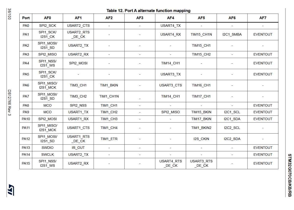
Tabelle der alternativen Port-Funktionszuweisungen eines Mikrocontrollers
_TX - - - EVENTOUT PA15 SPI1_NSS/I2S1_WS USART2_RX - - USART4_RTS_DE_CK USART3_RTS_DE_CK EVENTOUT STM32G070CB/KB/RB
in „UART und I2C Konflikt mit STM32duino STM32G070“ · Mikrocontroller und Digitale Elektronik · · Screenshots
-
Datei
jlink.txt
0x4BA00477, IRLen: 04, IRPrint: 0x1, CoreSight JTAG-DP (ARM) #1 Id: 0x06413041, IRLen: 05, IRPrint: 0x1, STM32 Boundary Scan Cortex-M4 identified. JTAG speed: 100 kHz J-Link>h WARNING: CPU could not be halted J-Link>
in „[STM32/Cortex-M4] JTag nur beim Systemflash möglich. Fehler beim Mainflash“ · Mikrocontroller und Digitale Elektronik ·
-
Datei
main.c
#include <stdio.h> #include "stm32f3xx.h" #include "usb.h" // The current clock frequency uint32_t SystemCoreClock=8000000; // Counts milliseconds volatile uint32_t systick_count=0; // Interrupt handler void SysTick_Handler(void) {
in „An W.S.: Läuft deine USB Implementierung auch auf STM32F303?“ · Mikrocontroller und Digitale Elektronik ·
-
Datei
main.c
#include <stdlib.h> #include <stm32g031xx.h> /*! * \brief Configures pin 5 ("PA11") as digital output. */ void config_output(void) { RCC->IOPENR |= RCC_IOPENR_GPIOAEN; GPIOA->MODER &= ~(0x3u << (11 * 2)); GPIOA->MODER |= (0x1u << (11
in „Crash @ TIM2-Überlauf statt TIM2_IRQHandler (STM32G031J6)“ · Mikrocontroller und Digitale Elektronik ·
-
Datei
main.txt
nc 8 nc nc 9 nc nc 10 nc nc 11 D4 PD0 12 D5 PD1 13 D6 PD2 14 D7 PD3 15 nc nc 16 nc nc */ #include "stm32f4xx.h" uint32_t i; void WriteNibble(char data){ GPIOD->BSRRL |= data; GPIOD->BSRRH |= ~data; GPIOD->BSRRL |= (1<<6); //E=1; for (i=0;i<10000;i++){} //delay GPIOD->BSRRH |= (1<<6); //E=0; for (i=0;i
in „STM32: Ich finde einfach keinen Fehler in meinem Code“ · Mikrocontroller und Digitale Elektronik ·
-
Datei
tim.h
#endif /* Includes ------------------------------------------------------------------*/ #include "stm32f4xx_hal.h" /* USER CODE BEGIN Includes */ /* USER CODE END Includes */ extern TIM_HandleTypeDef htim5; extern TIM_HandleTypeDef htim9; /* USER CODE BEGIN Private defines */ /* USER CODE END Private
in „STM32F4 HAL TIMER Interrupt läuft nicht“ · Mikrocontroller und Digitale Elektronik ·
-
Datei
delay.c
#include "delay.h" #include "stm32f0xx_hal.h" // For store tick counts in us static __IO uint32_t usTicks; /** System Clock Configuration */ void SystemClock_Config(uint32_t sysTickDevider) { RCC_OscInitTypeDef RCC_OscInitStruct; RCC_ClkInitTypeDef
in „Interrupt wird ständig aufgerufen“ · Mikrocontroller und Digitale Elektronik ·
-
Datei
log.txt
delay_init... board_led_init... button_init... timer2_init... wpsbutton_init... Version: 2.9.4 Hardware: STM32F103 Display: WC12h LEDs: WS2812 GRB rtc is online eeprom is online ws2812: external pullup detected eeprom is online current eeprom version: 0x00020900 reading ir codes from eeprom DFPLAYER LOGGER
-
PDF
Schaltplan.pdf
PA2 1k 2 R3 BC337-40 1 3 PA3 1k Q4 Minuten Einer R4 2 BC337-40 3 GND Binäruhr mit Blue-Pill Board (STM32F103C8T6) 14.10.2017 1.0
-
Datei
PWM_code.c
#include "stm32f10x_conf.h" unsigned int Sinus[20]= {32768,42893,52028,59277,63931,65535,63931,59277,52028,42893, 32768,22642,13507,6258,1604,0,1604,6258,13507,22642}; int i =0; int main(void) { GPIO_InitTypeDef GPIO_InitStructure
in „Sinuswerte für PWM berechnen“ · Mikrocontroller und Digitale Elektronik ·
-
Datei
main.c
#include "stm32f4xx.h" __attribute__((always_inline)) inline void bitCopy( uint32_t *dest, const uint8_t dstBit, const uint32_t src, const uint8_t srcBit ) { register uint32_t temp; __asm__ __volatile__ ( "UBFX %[
in „STM32F4 Compiler bremst den Code“ · Mikrocontroller und Digitale Elektronik ·
-
Datei
sample_code_main.c.txt
#include "stm32f10x.h" volatile unsigned int TimeTick=0; volatile unsigned int oneMsTick=0; void TIM3_IRQHandler(void) { //debugging: one high-pulse on GPIO A3 GPIOA->BSRR = GPIO_Pin_3; GPIOA->BRR = GPIO_Pin_3; TimeTick
in „STM32: Timer-ISR löst 2x aus - Fehler im Flag-Reset bei Optimierung O3“ · Mikrocontroller und Digitale Elektronik ·
-
Datei
USART.h
UART_NAME_t uart, char *ptr); //-------------------------------------------------------------- #endif // __STM32F4_UB_UART_H
in „STM32F0 Discovery und UART1“ · Mikrocontroller und Digitale Elektronik ·
-
Datei
dma.h
endif #endif #if defined(DMA2_CHANNELS) #if DMA2_CHANNELS == 0 #undef DMA2_CHANNELS #elif !defined(STM32L1XX_HD) #error DMA2 isn''t supported by your device. #else #error DMA2 not supported yet. #endif #endif typedef struct { void (*transfer_ends) (uint8_t dma_channel_number); void (*transfer_error) (
in „STM32L1xx DMA+SPI: 2 Bugs“ · Mikrocontroller und Digitale Elektronik ·
-
Datei
main.c
#include "stm32l0xx.h" // The current clock frequency uint32_t SystemCoreClock=2097000; // Change system clock to 32 MHz using 8 MHz crystal void init_clock() { // Wait until voltage regulator is stabilized while(
in „STM32L073RZ läuft auf HSE nur halb so schnell wie erwartet“ · Mikrocontroller und Digitale Elektronik ·
-
Datei
main.c
#include <stdio.h> #include "stm32f3xx.h" #include "usb.h" // The current clock frequency uint32_t SystemCoreClock=8000000; // Counts milliseconds volatile uint32_t systick_count=0; // Interrupt handler void SysTick_Handler(void) {
in „An W.S.: Läuft deine USB Implementierung auch auf STM32F303?“ · Mikrocontroller und Digitale Elektronik ·
-
Datei
main.c
#include <stdio.h> #include "stm32f3xx.h" #include "usb.h" // The current clock frequency uint32_t SystemCoreClock=8000000; // Counts milliseconds volatile uint32_t systick_count=0; // Interrupt handler void SysTick_Handler(void) {
in „An W.S.: Läuft deine USB Implementierung auch auf STM32F303?“ · Mikrocontroller und Digitale Elektronik ·
-
Datei
init_io.c
folgender Pinbelegung: // PA4: CSB (NSS) // PA5: SCK // PA7: MOSI (SI) // MISO wird nicht verwendet // STM32 ist Master, d. h. MSTR = 1 // Es wird Mode 3 verwendet, d. h. CPOL = 1 und CPHA = 1 // MSB wird zuerst gesendet, d.h. LSBFIRST = 0 (RESET-Status) // Datenlänge 8 Bit, d. h. DS[3:0] = 0x07 // SPI Baudrate
in „STM32F303 SPI kein SCK- und MOSI-Signal“ · Mikrocontroller und Digitale Elektronik ·
-
Datei
txtlcd_demo.c
Displayanschluss an den Controller ---------------------------------------------------------- o +5V | Display STM32F030F4P6 (TSSOP20) _ Funktion PIN PIN Funktion | | |_| GND 1 ------------ | +5V 2 ------------ o----o Kontrast --- Kontrast 3 ------------ _|_ RS 4 ------------ 11 PA5 \ / rd /wr 5 ------------ GND
in „Live-Linux: Anleitung schreiben“ · PC Hard- und Software ·
-
Datei
cm3-systick.c
#include "config.h" #include "stm32/cm3-systick.h" ///////////////////////////////////////////////////////////////////////////// #if Systick_Delay #define DELAY_OVERHEAD (18 * (1000000000 / F_HCLK)) static unsigned delay_ns_per_tick
in „[ARM / Cortex-M0(+)] delay-Funktionen "avr-libc style"“ · Projekte & Code ·
-
Datei
main.cpp
#include <stdlib.h> #include <stm32g031xx.h> /*! * \brief Configures pin 5 ("PA11") as digital output. */ void config_output(void) { RCC->IOPENR |= RCC_IOPENR_GPIOAEN; GPIOA->MODER &= ~(0x3u << (11 * 2)); GPIOA->MODER |= (0x1u << (11
in „Crash @ TIM2-Überlauf statt TIM2_IRQHandler (STM32G031J6)“ · Mikrocontroller und Digitale Elektronik ·
-
Datei
sdram_fx.c
/* SDRAM FX nützliche Routinen für die SDRAM Initialisation Markus Horbach 04.09.2016 für STM32CubeMX */ #include "sdram_fx.h" static FMC_SDRAM_CommandTypeDef Command; // local extern SDRAM_HandleTypeDef hsdram1; // fmc.c void SDRAM_Initialization_sequence(uint32_t RefreshCount) { __IO uint32
in „STM32F7 und SDRAM“ · Mikrocontroller und Digitale Elektronik ·
-
PDF
TheHelper.pdf
1+2) 26 PB3 19 27 PB4 PA9 20 GND PA10 29 PB6 PA11 21 31 22 PB8 PA12 +3.3V +3.3V S SA S S V V 1 1 STM32G431KBUx C C C5 C6 100n/50V 1u/50V GND GND GND Sheet: / D File: TheHelper.kicad_sch D Title: Size: A4 Date: Rev: KiCad E.D.A. 9.0.2 Id: 1/1 1 2 3 4 5 6
in „Schaltplancheck Powermonitor“ · Mikrocontroller und Digitale Elektronik ·
-
PDF
TheHelper.pdf
1+2) 26 PB3 19 27 PB4 PA9 20 GND PA10 29 PB6 PA11 21 31 22 PB8 PA12 +3.3V +3.3V S SA S S V V 1 1 STM32G431KBUx C C C5 C6 100n/50V 1u/50V GND GND GND Sheet: / D File: TheHelper.kicad_sch D Title: Size: A4 Date: Rev: KiCad E.D.A. 9.0.2 Id: 1/1 1 2 3 4 5 6
in „Schaltplancheck Powermonitor“ · Mikrocontroller und Digitale Elektronik ·
-
Datei
USB.c
/* ST STM32F103ZET6: USB als COM Port betreiben */ #include "usb.h" /* die Transfer-Puffer für zeichenweises In und Out über den USB */ #define txLen 256 char UsbTxBuf[txLen]; int txr, txw; #define rxLen 256 char
in „Frage an W.S. wegen USB CDC Implementierung STM32F103“ · Mikrocontroller und Digitale Elektronik ·
-
Datei
main.c
Includes ----------------------------------------------------------------------------------*/ #include "stm32f10x.h" #include "usart.h" #include <stdio.h> void spi_init(){ //CS = PB12 (General Purpose Output) //CLK = PB13 (Alternative Function, Push Pull) //SDI(MISO) = PB15 (Input Pull-Up) //SDO(MOSI) = PB14
in „[STM32] CMD0 liefert immer 0xFF zurück“ · Mikrocontroller und Digitale Elektronik ·
-
Datei
rfm12.h
RFM12_H_ /* Includes ------------------------------------------------------------------*/ #include "stm32f10x.h" /* Private typedef -----------------------------------------------------------*/ typedef union conver_ { unsigned long dw; unsigned int w[2]; unsigned char b[4]; } CONVERTDW; typedef union conver2
in „RFM12 und STM32F1xx“ · Mikrocontroller und Digitale Elektronik ·
-
Datei
rtc_stmf1.c
write operation on RTC registers has finished */ RTC_WaitForLastTask(); } ///////////////////// BEI stm32f10x_it.c void RTC_IRQHandler(void) { GPIO_SetBits(GPIOA, LED1_SEKUNDEN); if (RTC_GetITStatus(RTC_IT_SEC) != RESET) { /* Clear the RTC Second interrupt */ RTC_ClearITPendingBit(RTC_IT_SEC); /* Toggle
in „STM32F1 RTC eine Sekunde generieren“ · Mikrocontroller und Digitale Elektronik ·
-
Datei
main_und_rcc.c
------------------------------------------------------------------*/ #include "main.h" #include "stm32f10x_conf.h" /* Private typedef -----------------------------------------------------------*/ /* Private define ------------------------------------------------------------*/ /* Private macro ------
in „STM32F1 RTC eine Sekunde generieren“ · Mikrocontroller und Digitale Elektronik ·
-
Datei
main.c
#include "stm32f10x.h" #include "math.h" #define PI 3.1415926535897932384626433832795 #define rLDC 250.0 #define ARMLENGTH 500.0 #define ARMLENGTH2 250000.0 uint32_t readings[16]; uint8_t index = 0; uint32_t avg =
in „Mikrocontroller Rechenleistung reicht für aktuelles Projekt nicht?“ · Mikrocontroller und Digitale Elektronik ·
-
Datei
t.m
\ml_fft_8k.wav'); [st,fs2,nbits2]=wavread('c:\interim\st_fir_8k.wav'); load c:\interim\fir_design_stm32f4\pdmsignal.mat; plot(1:length(st),20*log10(abs(fft(st))),'r.-',1:length(ml),20*log10(abs(fft(ml))),'b.-'); signal=signal-mean(signal); %xx=signal(1:127*fix(length(signal)/127)); %xx=reshape(xx,127
in „FIR Filter Optimierung eines PDM Signals auf STM32F407 simuliert mit Matlab“ · Digitale Signalverarbeitung / DSP / Machine Learning ·
-
Datei
gpio.h
#ifndef GPIO_H_ #define GPIO_H_ #include "stm32l4xx_hal_rcc.h" #define PORTMODE_OFFSET 0x00 #define MODE_OUTPUT 0x1 #define MODE_INPUT 0x0 #define ODR_OFFSET 0x14 #define IDR_OFFSET 0x10 #define AHB2ENR_REGOFFS 0x4c #define PIN_CENTER 0 #define
in „STM32L4 LED durch Tastedrücken einschalten“ · Mikrocontroller und Digitale Elektronik ·