-
PDF
ad620.pdf
F20,000 (3 OP-07s) I p BIPOLAR INPUT O N V 100 IN-AMP M E – P15,000 A z R L 1 O AD620A V 1 10 R10,000 T ( G = 100 L RG R AD620 SUPERßETA T 5,000 1 IN-AMPR INPUT T 0 0.1 0 5 10 15 20 1k 10k 100k 1M 10M 100M SUPPLY CURRENT – mA SOURCE RESISTANCE – Three Op Amp IA Designs vs. AD620 Total Voltage Noise vs.
in „Verständnisproblem Beschaltung Instrumentenverstärker“ · Analoge Elektronik und Schaltungstechnik ·
-
PDF
Mainboard_Board.pdf
S4301B S4301B S4301B C1 47uF F 2 1 MAX7219CNG , C I 0 P R1 J 10k D3 0 R 1 SFH482 R8 A17,5mm D2 D10 T1 1N4148DO35-17N4148DO35-7 k 6 k 7 5 3 1 2 3 1 R 0 R 2 2 1 Q D 1 B C12 10nF B1 100nF 5C11 3 k 10k N R 6 2 r R22 4 J a OK2 o 100k b 4 5 R21 n 5 74HCT14N R 1 i I a t M M r D D6 L A i C t 1 0 e A17,5mm R 1 n T2 SFH482 R12 0 y 100 8 C D5 D4 1 1 2 3 1N4148DO35-17N4148DO35-7 5 0 1 3 3 1 1 R 2 D 2 1 Q B 1 J C6 470uF C9 F 4 F C7 0 C ISP 0 0 47nF 1 m C 1 3 2 1 3 5 2 F 1 0 z2RpF 4 2 T 1 1 0 R C M Q A IC4 6 AT90LS8535J-S
in „MAX7219: 3-Segment-Anzeige macht Probleme“ · Mikrocontroller und Digitale Elektronik ·
-
PDF
ersatzlampenliste.pdf
Boxlight CP305t 200W P22 (65*70mm) LF200P22 Boxlight CP306t 200W P22 (65*70mm) LF200P22 Boxlight CP310t 200W P22 (65*70mm) LF200P22 Boxlight CP315t 200W P22 (65*70mm) LF200P22 Boxlight CP731i 160W P22 (65*70mm) LF150P22 Boxlight MP25t 150W P23 (95*95mm) LF150P23 Boxlight MP35t 150W P23 (95*95mm) LF150P23 Boxlight MP36t 200W P23 (95*95mm) LF200P23 Boxlight Mp37t 200W P23 (95*95mm) LF200P23 Boxlight Mp38t 200W P23 (95*95mm)
in „Beamer 'wiederverwerten'?“ · Mikrocontroller und Digitale Elektronik ·
-
PDF
U2008b.pdf
Figure 5-1. Ramp Control 250 ) ( α 200 33 nF 10 nF6.8 nF4.7 nF3.3 nF 2.2 nF l g A 150 e a h 100 Cϕ/t = 1.5 nF P 50 0 0 200 400 600 800 1000 R ϕR 8 (kΩ) 7 4712B–AUTO–10/05 Figure 5-2. Pulse Output 120 VGT = -1.2 V 100 80 ) A ( 60 T I 40 20 0 0 200 400 600 800 1000 R (Ω) GT Figure 5-3. Output Pulse Width 400 ∆p /ϕC = 9 µs/nF 300 s ( 200 p t 100 0 0 10 20 30 C (nF) ϕ Figure 5-4. Option Soft Start 1 C5= 1 µF 0 -1 ) 10 µF ( 1 -2 V -3 Supply R = 22 kΩ/2 W 1 -4 4.7 µF C 1= 100 µF/25 V -5 0 1 2 3 4 5 t ( s ) 8 U2008B 4712B–AUTO–10/05 U2008B Figure
in „Phase Control IC u2008b“ · Mikrocontroller und Digitale Elektronik ·
-
PDF
LM10.pdf
Package 45˚C/W Vapor Phase (60 seconds) 215˚C Infrared (15 seconds) 220˚C Electrical Characteristics T =25˚C, T ≤T ≤T (Boldface type refers to limits over temperature range) (Note 5) J MIN J MAX Parameter Conditions LM10/LM10B LM10C Units Min Typ Max Min Typ Max Input offset voltage 0.3 2.0 0.5 4.0 mV
in „Labornetzgerät als Projekt“ · Analoge Elektronik und Schaltungstechnik ·
-
PDF
ads831.pdf
20 VDRV Output Logic Driver Supply Voltage TIMING DIAGRAM N+1 N+2 N+4 Analog In N+3 N+7 N N+5 N+6 tD tCONV L H Clock 4 Clock Cycles t2 Data Out N–4 N–3 N–2 N–1 N N+1 N+2 N+3 Data Invalid t 1 SYMBOL DESCRIPTION MIN TYP MAX UNITS CONV Convert Clock Period 12.5 100µs ns L Clock Pulse Low 5.8 6.25 ns t
-
PDF
MCP41010.pdf
4 +1 LSB Note 2 Rheostat Integral Non Linearity R-INL -1 ±1/4 +1 LSB Note 2 Rheostat Tempco ∆R AB/∆T — 800 — ppm/°C Wiper Resistance RW — 52 100 Ω V DD= 5.5V,WI= 1 mA, code 00h R — 73 125 Ω V = 2.7V, I= 1 mA, code 00h W DD W Wiper Current IW -1 — +1 mA Nominal Resistance Match ∆R/R — 0.2 1 % MCP42010
in „Widerstand regeln“ · Mikrocontroller und Digitale Elektronik ·
-
PDF
11195c.pdf
4 +1 LSB Note 2 Rheostat Integral Non Linearity R-INL -1 ±1/4 +1 LSB Note 2 Rheostat Tempco ∆R AB/∆T — 800 — ppm/°C Wiper Resistance RW — 52 100 Ω V DD= 5.5V,WI= 1 mA, code 00h R — 73 125 Ω V = 2.7V, I= 1 mA, code 00h W DD W Wiper Current IW -1 — +1 mA Nominal Resistance Match ∆R/R — 0.2 1 % MCP42010
in „DC-DC Wandler mit MCP42010“ · Mikrocontroller und Digitale Elektronik ·
-
PDF
mcp41xxx.pdf
4 +1 LSB Note 2 Rheostat Integral Non Linearity R-INL -1 ±1/4 +1 LSB Note 2 Rheostat Tempco ∆R AB/∆T — 800 — ppm/°C Wiper Resistance RW — 52 100 Ω V DD= 5.5V,WI= 1 mA, code 00h R — 73 125 Ω V = 2.7V, I= 1 mA, code 00h W DD W Wiper Current IW -1 — +1 mA Nominal Resistance Match ∆R/R — 0.2 1 % MCP42010
in „Schaltregler, Feedback und Op Amp“ · Analoge Elektronik und Schaltungstechnik ·
-
Datei
ch32v003.c
0b01101101, // 5 0b01111101, // 6 0b00000111, // 7 0b01111111, // 8 0b01101111 // 9 }; void Delay_ms(uint32_t ms); void I2C_Init_Custom(void); uint8_t TMP101_ReadTemperature(void); void Display_Update(void); void Display_SetDigit(uint8_t digit, uint8_t value); int main(void) { SystemInit(); I2C_Init_Custom()
in „Copilot für MCUs“ · Mikrocontroller und Digitale Elektronik ·
-
PDF
Bandwidth_Versus_Video_Resolution.pdf
resolution can be calculated from the signal bandwidth (BW ) bySusing the following equation: TVL = (2 t HA BW )SAR EQ 2 Where: TVL = Horizontal resolution specified in TV lines tHA = Active horizontal period BW S = Signal bandwidth AR = Aspect ratio (the width of the display divided by the height of the
in „VGA Schalten“ · Analoge Elektronik und Schaltungstechnik ·
-
PDF
muRata_TZC3P200A110_.pdf
Characteristics TZC3R100 TZC3P200 R100 P200 1000 1000 1000 1000 ) Q 100 p Q F 100 ( 100 100 ( c c t a c c p p C C 10 10 10 10 1 1 200 400 600 800 1000 200 400 600 800 1000 Frequency (MHz) Frequency(MHz) Land Pattern Standard Type Cross Slot Type +0 +0 5.0 −0.5 5.0−0.5 3.3±0.1 3.3±0.1 5 . . ± ± . .
in „Wittig(welec) DSO W20xxA Hardware (Teil 2)“ · Mikrocontroller und Digitale Elektronik ·
-
PDF
NODEMCU_DEVKIT_V1_0.PDF
ORGANIZATION D NODE MCU TEAM D WEBSITE WWW.NODEMCU.COM 1 2 3 4 1 2 3 4 POWER A A VDD5V U4 NCP1117ST33T3G VDD3V3 P I U VIN 3 DVOUT P I U 4 0 2 C7C1 / P1CO8 N VDDUSB VDD5V 10uF 25V G P2 10uF 1 D1D GND U1 GND PID10PID102 1N5819/SS14/S4(SOD_323) GND B Working Output: 3.3V 800mA B Working Current Limit: 1000mA Max Current: 1000mA Max Supply Voltage: 20V Voltage Dropout:1.2V@800mA C C VER DATE 1.0 28/01/2015 ORGANIZATION D NODE MCU TEAM D WEBSITE WWW.NODEMCU.COM 1 2 3 4 1 2 3 4 IO CONN COJ COJ A J1 J2 A ADC_EX P I J 1 PIN1 PIN1 P I J 2 0 116IO ADCD P I J 1 PIN2 PIN2 P I J 2
in „NodmCU ESP8266 nicht zu flashen“ · Mikrocontroller und Digitale Elektronik ·
-
PDF
SEMIKRON_DataSheet_SKR_96_02643980.pdf
, SKR 96 VRSM VRRM IFRMS= 150 A (maximum value for continuous operation) V V IFAV= 95 A (sin. 18c; T = 142 ºC) 200 200 SKN 96/02 SKR 96/02 400 400 SKN 96/04 SKR 96/04 800 600 SKN 96/08 SKR 96/08 1200 1200 SKN 96/12 SKR 96/12 Symbol Condition Values Units FAV sin. 180 ; C = 142 ºC 95 A Stud Diode ; T
in „Dioden identifizieren“ · Analoge Elektronik und Schaltungstechnik ·
-
PDF
MotorolaDatenCD_2000.pdf
18.4 500 18 200 MRF9511LT1 (18c) 8.0 30 16 2.1 2000 9.0 2000 10 100 Case 419/3 — SC–70/SOT–323 MRF917T1 (18c) 6.0 20 8 2.3 1000 10 1000 12 60 MRF577T1 (18c) 7.0 40 12 1.5 1000 10 1000 10 80 (18c) MRF927T1 8.0 5.0 14 1.7 1000 9.8 1000 10 10 MRF927T3 (18d) 8.0 5.0 14 1.7 1000 9.8 1000 10 10 MRF947T1 (18c
-
PDF
u2010b.pdf
° ( α 200 33 nF10 nF 3.3 nF 2.2 nF l 6.8 nF 4.7 nF n A 150 e a h P 100 Cϕ/t = 1.5 nF 50 0 0 200 400 600 800 1000 Rϕ (R ) (kΩ) 8 Figure 7-2. Pulse Output 120 VGT= -1.2 V 100 ) 80 A ( G 60 I 40 20 0 0 200 400 600 800 1000 R (Ω) GT Figure 7-3. Output Pulse Width 400 ∆p /∆Cϕ = 9
in „U2010B Softstart Funktion“ · Mikrocontroller und Digitale Elektronik ·
-
PDF
BK4802N_Datasheet_V1.1_EN.pdf
Pulse Suppression tSP — — 40 ns t t t t t t t t t SU:STHD:STA LOW HIGH r:IN f:IN SP SU:STBUF SCLK // // SDIO // START STOP START tr:IN HD:DAT SU:DAT f:IN, f:OUT Figure 3Read/Write Timing of I2C Interface Proprietary and
in „Tranceiver Chip RDA1846 Erfahrungen Selbstbau“ · HF, Funk und Felder ·
-
PDF
122855-da-01-de-OSZILLOSKOP_TDS2004B.pdf
Funktionen am Seitenteil und auf der Rückseite 11 12 9 8 10 8 USB-Gerätesc®nittstelle kombiniert m®t 9 USB-Geräte®chnittstelle kombiniert mit 11 Integrierter Griff – so können Sie das OpenChoice und NI SignalExpress TE PictBridge für den Direktdruck – hiermit ultraleichte (2,0 kg) Messgerät leichter
in „Digitalspeicher-Oszilloskop“ · Mikrocontroller und Digitale Elektronik ·
-
PDF
FFM.pdf
Measurement Technique are used with differential amplifiers and can be V oltage Isolator Measurement T echnique calibrated for precisely matching the DC and AC “A minus B” Measurement Technique attenuation in both signal paths (including the reference lead). “Floating” the Oscilloscope Technique Floating
-
Datei
Status_LED_Final_1.ino
#define NUMPIXELS 40 Adafruit_NeoPixel Pixels = Adafruit_NeoPixel(NUMPIXELS, PIN, NEO_GRB + NEO_KHZ800); int LED_Ausgabe[8][4] = //Belegung Feld - LED { {0, 1, 6, 7}, //A3 {1, 2, 7, 8}, //A4 {2, 3, 8, 9}, //A5 {4, 5, 12, 13}, //B1 {5, 6, 13, 14}, //B2 {6, 7, 14, 15}, //B3 {7, 8, 15, 16}, //B4 {8, 9,
in „Switch-Case Anweisung - Frage“ · Mikrocontroller und Digitale Elektronik ·
-
PDF
TEM-U2400B-.pdf
V V . . . . . r u 0 0 2 0 0 h u + – + – + – – + – + o C o g a o r x i i e n i m a o a p S o V i g t M c c ts m o a p y i r in s ut s D t o D o B t g a t a S t e o C p e nt c z t E o 5 S c 6 W 0 R 0 e g t 3 6 T l i e 1 n R u l g r a 4 n n c 5 r o i s a u H g C D a p t T e f u S d uo 9 R o t S 4 n M
in „NI-CD Batterielader mit U2400B“ · Analoge Elektronik und Schaltungstechnik ·
-
PDF
LC4104C.pdf
5625.0 –825.0 194 NC –1125.0 –825.0 165 V 5400.0 –825.0 195 LOAD –1350.0 –825.0 DDH 166 NC 5175.0 –800.0 196 NC –1575.0 –825.0 167 V2 4950.0 –800.0 197 M –1800.0 –825.0 168 NC 4725.0 –800.0 198 NC –2025.0 –825.0 169 V0 4500.0 –800.0 199 DISP –2250.0 –825.0 170 NC 4275.0 –825.0 200 NC –2475.0 –825.0 171
in „Display von Pollin - Datenblatt - Ansteuerung“ · Mikrocontroller und Digitale Elektronik ·
-
PDF
LT1638.pdf
250 800 µV OS 0°C ≤ T ≤ 70°C ● 1000 µV A –40°C ≤ A ≤ 85°C ● 1100 µV LT1639 N, S Packages 350 900 µV 0°C ≤ T ≤ 70°C ● 1100 µV A –40°C ≤ A ≤ 85°C ● 1200 µV LT1638 MS8 Package 400 1050 µV 0°C ≤ A ≤ 70°C ● 1250
in „OPAMP Differenzverstärker - max. Einganggsspannung?“ · Analoge Elektronik und Schaltungstechnik ·
-
PDF
XC95288_Auszug.pdf
CPLD XC95288XL Global, JTAG and Power Pins (1) Pin Type TQ144 PQ208 BG256 FG256 CS280 I/O/GCK1 30 44 T2 M2 R3 I/O/GCK2 32 46 U2 M3 T1 I/O/GCK3 38 55 W4 P5 W2 I/O/GTS1 5 7 C1 D4 D3 I/O/GTS2 6 9 E1 E5 E2 I/O/GTS3 2 3 C2 D3 C2 I/O/GTS4 3 5 D3 E3 C1 I/O/GSR 143 206 A2 C4 C4 TCK 67 98 U16 P12 T15 TDI 63 94
in „miniLa Software“ · Projekte & Code ·
-
PDF
IXRA15N120.pdf
IC90 T C= 90°C 15 A - soft reverse recovery ICM V GE0/15 V; R G 47 Ω;T = VJ5°C 30 A • positive temperature coefficient of VCEK RBSOA; Clamped inductive load; L = 100 µH 600 V saturation voltage • Epoxy of package
in „RB IGBT Beschaltung“ · Analoge Elektronik und Schaltungstechnik ·
-
Datei
DCF77.c
define DCF_DDR DDRD #define DCF_BIT _BV(7) // upper 16 bit of timer (overflow) static volatile uint16_t tick_hi = 0; static volatile struct { uint16_t clk; // last timestamp uint8_t index; // bitstream index uint8_t spike:1; // spike has been detected uint8_t valid:1; // DCF data is valid uint8_t error
-
PDF
4051.pdf
Test Circuit ON TYPICAL RESISTANCE CHARACTERISTICS 350 350 ) 300 ) 300 S S H H ( 250 ( 250 E E N N T 200 T 200 I I E 150 E 150 T =125⋅C ” TA=125⋅C ” A O O , 100 , 100 25⋅C N 25⋅C N RO –55⋅C R –55⋅C 50 50 0 0 –10 –8.0 –6.0 –4.0 –2.0 0 0.2 4.0 6.0 8.0 10 –10 –8.0 –6.0 –4.0 –2.0 0 0.2 4.0 6.0 8.0 10 VinINPUTVOLTAGE
in „V: MC14051BCP“ · Markt ·
-
PDF
4051.pdf
Test Circuit ON TYPICAL RESISTANCE CHARACTERISTICS 350 350 ) 300 ) 300 S S H H ( 250 ( 250 E E N N T 200 T 200 I I E 150 E 150 T =125⋅C ” TA=125⋅C ” A O O , 100 , 100 25⋅C N 25⋅C N RO –55⋅C R –55⋅C 50 50 0 0 –10 –8.0 –6.0 –4.0 –2.0 0 0.2 4.0 6.0 8.0 10 –10 –8.0 –6.0 –4.0 –2.0 0 0.2 4.0 6.0 8.0 10 VinINPUTVOLTAGE
in „Einfache Multiplex Schaltung (Anfänger!)“ · Mikrocontroller und Digitale Elektronik ·
-
PDF
LT1498.pdf
Current (Output High) vs Load Current (Output Low) 400 1000 1000 VS= p15V 300 VCM = 15V ) ) ) n 200 m m T NPN ACTIVE VS= 5V, 0V E E E 100 VCM = 5V G100 G100 R T T U O O TA= 25°C C 0 V V TA= 125°C I I I B–100 V = p15V A A U PNP ACTIVE S R 10 R 10 TA= –55°C N–200 VCM = –15V T TA= –55°C T I S S VS= 5V, 0V T
in „KSQ für LED mit OPV“ · Analoge Elektronik und Schaltungstechnik ·
-
Datei
terror.txt
IRQ 18 [ 30.405450] saa7134[1]: found at 0000:03:05.0, rev: 1, irq: 18, latency: 32, mmio: 0xdfeff800 [ 30.405457] saa7134: <rant> [ 30.405458] saa7134: Congratulations! Your TV card vendor saved a few [ 30.405460] saa7134: cents for a eeprom, thus your pci board has no [ 30.405461] saa7134: subsystem ID and I can't identify it automatically [ 30.405462] saa7134: </rant> [ 30.405463] saa7134: I feel better now. Ok, here are the good news: [ 30.405465] saa7134: You can use the card=<nr> insmod option to specify [
in „linux ubuntu SAA7134 zwei identische TV-Karten“ · PC Hard- und Software ·
-
PDF
Duracell-MN1604-9V-Plus.pdf
standards TYPICAL DISCHARGE CHARACTERISTICS AT 21 °C (70°F) 9.5 100 OHM 200 OHM 8.5 500 OHM 1000 OHM e t7.5 o V 6.5 5.5 Berkshire Corporate Park Bethel, CT 06801 U.S.A. Telephone: Toll-free 1-800-544-5454 Internet: www.duracell.com 4.5 0 10 20 30 40 50 60 70 80 90 100 Service Hours * Delivered capacity
in „Wofür 9V Blockbatterien“ · Mikrocontroller und Digitale Elektronik ·
-
Datei
main.cpp
include <util/delay.h> #include <avr/interrupt.h> #include <stdlib.h> #include <avr/sleep.h> uint16_t rfm12_trans(uint16_t cmd) { uint16_t res; SPI_PORT &= ~(1<<NSEL); SPDR = cmd >> 8; loop_until_bit_is_set(SPSR, SPIF); res = SPDR << 8; SPDR = cmd & 0xFF; loop_until_bit_is_set(SPSR, SPIF); res |= SPDR
in „Seltsames SPI Verhalten (Mega88, RFM12)“ · Mikrocontroller und Digitale Elektronik ·
-
PDF
LTC224210fc.pdf
Demultiplexed CMOS Outputs with Interleaved Update All Outputs Are Single-Ended and Have CMOS Levels tAP N + 2 N + 4 ANALOG N INPUT N + 3 t H N + 1 tL – ENC ENC + tD N – 5 N – 3 N – 1 DA0-DA9, OFA tD DB0-DB9, OFB N – 6 N – 4 N – 2 tC tC CLKOUTB CLKOUTA 224210 TD03 Demultiplexed CMOS Outputs with Simultaneous
in „Projekt Signal-Auswertung mit High-Speed-ADC“ · Mikrocontroller und Digitale Elektronik ·
-
Datei
cj_gol.c
Zustände der nächsten Generation #define DEAD 0 #define ALIVE 1 // 2 Spielfelder alt+neu struct feld_t { uint8_t last[MAX_X+1][MAX_Y+1]; uint8_t next[MAX_X+1][MAX_Y+1]; }; // Pixelfeld anlegen struct feld_t RAM feld; uint32_t cells; uint16_t changes = 0; /* 23/3 Regel Geburt: = 3 Nachbarn Stirbt Einsamkeit
in „Bedarf an eigenbau STM32F429 Evaluation Board ?“ · Mikrocontroller und Digitale Elektronik ·
-
Datei
KnightRider.ino
_t pwmtable[32] PROGMEM = { 0, 1, 2, 2, 2, 3, 3, 4, 5, 6, 7, 8, 10, 11, 13, 16, 19, 23, 27, 32, 38, 45, 54, 64, 76, 91, 108, 128, 152, 181, 215, 255 }; uint8_t leds[LED_CNT][3]; uint8_t light[LED_CNT];
in „LED-Lauflicht im Knight Rider Style“ · Projekte & Code ·
-
Datei
vga_pkg.vhd
CEIL(LOG2(REAL(c_vbp+1)))); CONSTANT c_vfp_bits : integer := INTEGER(CEIL(LOG2(REAL(c_vfp+1)))); type t_palette_rom is array(0 to 15) of std_logic_vector(7 downto 0); subtype t_pixelvalue is std_logic_vector(c_bpp-1 downto 0); --4 bit Farbtiefe --type t_linebuffer is array(integer RANGE <>) of t_pixelvalue; --SIGNAL line : t_linebuffer(0 to c_hdisp-1); type t_linebuffer is array(0 to c_hdisp-1) of t_pixelvalue; --platz für eine Zeile type t_framebuffer is array(0 to c_vdisp-1) of t_linebuffer;--ganzer Framebuffer constant
-
 Bild
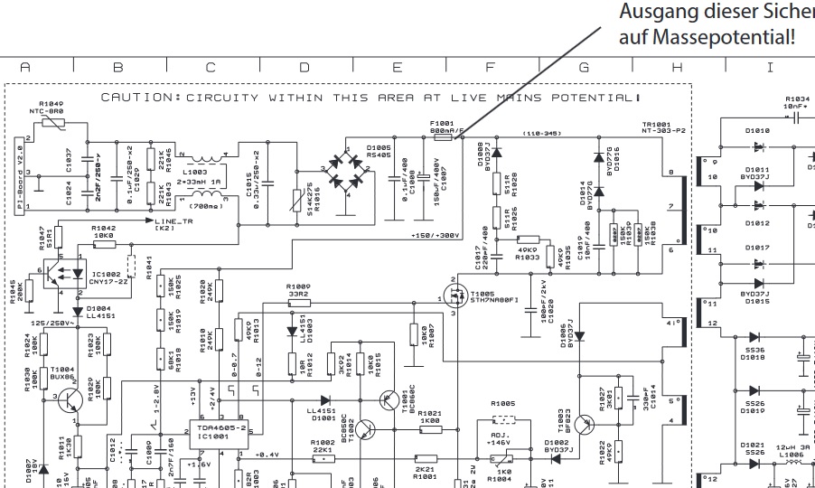
Schaltplan eines Netzteils
C1037 2nF/250V C1024 R1042 10K JC1082 CNY17-ZZ D1004 LL4S1 R1041 227K R1025 249K R1026 200K R1024 100K T1004 BUX86 R1011 1K30 C1012 2nF/250V T04605-2 IC1002 +1.6V +0.4V R1002 22K1 R1004 1K R1005 R1021 1K00 T1002 BOSC06 C1014 330uF R1003 2->33nH 1R C10150 0.33uF D1005 RS405 R1015 33uF F1001 800mA/P D1006
in „Hameg HM1507-3 Netzteil defekt“ · Analoge Elektronik und Schaltungstechnik · · Schaltpläne
-
PDF
INA138.PDF
//www.burr-brown.com/ • Cable:BBRCORP • Telex:066-6491 • FAX:(520)889-1510 • ImmediateProductInfo:(800)548-6132 ©1999 Burr-Brown Corporation PDS-1576B Printed in U.S.A. August, 2000 SBOS122 SPECIFICATIONS At T = –40°C to +85°C, V = 5V, V = 12V, R = 125k , unless otherwise noted. A S IN+ OUT INA138NA
in „Stromverbrauch am Akku messen“ · Mikrocontroller und Digitale Elektronik ·
-
PDF
ads830.pdf
Supply 20 VDRV Output Logic Drive Supply Voltage TIMING DIAGRAM N+2 N+1 N+4 Analog In N N+3 N+5 N+7 N+6 t t tD tCONV L H Clock 4 Clock Cycles 2 Data Out N–4 N–3 N–2 N–1 N N+1 N+2 N+3 Data Invalid 1 SYMBOL DESCRIPTION MIN TYP MAX UNITS t Convert Clock Period 16.6 100µs ns CONV L Clock Pulse Low 7.3 8.3 ns
in „ads830 ad wandler“ · Mikrocontroller und Digitale Elektronik ·
-
PDF
PCF8591.pdf
BIT 7 BIT 6 BIT 0 ACKNOWLEDGE STOP PROTOCOL CONDITION MSB (A6) LSB (A) CONDITION (S) (A7) (R/W) (P) t t t SU;STA LOW HIGH 1 / f SCL SCL tBUF tr tf SDA tHD;STA tSU;DAT tHD;DAT tVD;DAT MBD820 tSU;STO 2 Fig.19 I C-bus timing diagram; rise and fall times refer toIL and VIH 1998 Jul 02 20 Philips Semiconductors
in „Datentransfer an PCF8591“ · Mikrocontroller und Digitale Elektronik ·
-
PDF
PCF8591.pdf
BIT 7 BIT 6 BIT 0 ACKNOWLEDGE STOP PROTOCOL CONDITION MSB (A6) LSB (A) CONDITION (S) (A7) (R/W) (P) t t t SU;STA LOW HIGH 1 / f SCL SCL tBUF tr tf SDA tHD;STA tSU;DAT tHD;DAT tVD;DAT MBD820 tSU;STO 2 Fig.19 I C-bus timing diagram; rise and fall times refer toIL and VIH 1998 Jul 02 20 Philips Semiconductors
in „I2C Analog Mux/Demux im DIP gesucht“ · Mikrocontroller und Digitale Elektronik ·
-
Datei
rfm12.c
include <util/delay.h> #include <util/crc16.h> #include <avr/sleep.h> #include "rfm12.h" static uint8_t rfm12_nodeId = 0; static uint16_t rfm12_messageId = 0; static uint8_t rfm12_state = 0; void rfm12Cmd (uint16_t cmd) { uint8_t i; RFM12_SEL_LOW(); for(i = 0; i < 16; i++) { if(cmd & 0x8000) { RFM12_MOSI_HI
in „Code Optimierung (Geschwindigkeit) AVR, C“ · Mikrocontroller und Digitale Elektronik ·
-
PDF
1933fe.pdf
100 100 1200 TA= 25°C TA= 25°C TA= 25°C VOUT= 5V V OUT= 3.3V TYPICAL )1000 m 90 VIN= 12V 90 VIN= 5V T ) ) I 800 ( ( L MINIMUM C V = 24V C VIN= 12V T N 80 IN N 80 E 600 C C VIN = 24V R I I C E E H 400 T 70 70 W S 200 D1 = MBRM140 D1 = MBRM140 60 L1 = Toko D53LCB 33H 60 L1 = Toko D53LCB 22H 0 100 200 300
in „Kann ich eine BAS85 problemslos an Stelle einer 1N4148 verwenden?“ · Mikrocontroller und Digitale Elektronik ·
-
PDF
1933fe.pdf
100 100 1200 TA= 25°C TA= 25°C TA= 25°C VOUT= 5V V OUT= 3.3V TYPICAL )1000 m 90 VIN= 12V 90 VIN= 5V T ) ) I 800 ( ( L MINIMUM C V = 24V C VIN= 12V T N 80 IN N 80 E 600 C C VIN = 24V R I I C E E H 400 T 70 70 W S 200 D1 = MBRM140 D1 = MBRM140 60 L1 = Toko D53LCB 33H 60 L1 = Toko D53LCB 22H 0 100 200 300
in „LT Spice ein IC von Texas Insturments einbinden“ · Analoge Elektronik und Schaltungstechnik ·
-
PDF
CAN_Bit_Timing.pdf
(tBus+ tTx + tRx) (8) ‰ where t Busis the propagation delay of the signal along the longest length • of the bus between two nodes, t Tx is the propagation delay of the … transmitter part of the physical
in „Berechnung CAN-Bittiming / Samplepoint“ · Mikrocontroller und Digitale Elektronik ·
-
PDF
AN1798.pdf
(tBus+ tTx + tRx) (8) ‰ where t Busis the propagation delay of the signal along the longest length • of the bus between two nodes, t Tx is the propagation delay of the … transmitter part of the physical
-
PDF
NFAQ1560R43T-D.PDF
HIN(W) protection HS3 circuits LIN(W) LS3 LS1 LS2 LS3 D D T I U V W S F U T N N N C F I Figure 1. Function Diagram © Semiconductor Components Industries, LLC, 2020 1 Publication Order Number: February, 2021 − Rev. 1 NFAQ1560R43T/D NFAQ1560R43T RC filtering for
in „Ersatz für ON-Semi STK5Q4U362J-E / STK5Q4U363J-E bzw. passt da NFAQ1060L33T / NFAQ1060L36T“ · Analoge Elektronik und Schaltungstechnik ·
-
PDF
NFAQ1560R43T-D.pdf
HIN(W) protection HS3 circuits LIN(W) LS3 LS1 LS2 LS3 D D T I U V W S F U T N N N C F I Figure 1. Function Diagram © Semiconductor Components Industries, LLC, 2020 1 Publication Order Number: February, 2021 − Rev. 1 NFAQ1560R43T/D NFAQ1560R43T RC filtering for
in „Bosch WAV28K40/01 Serie 8 Waschmaschine - Trommel dreht nicht - E60-09 - Inverter, LNK304, TNY88PG“ · Analoge Elektronik und Schaltungstechnik ·
-
PDF
AAT3113.pdf
=3.6, V =3.3V 0.3 % IN any two outputs η Efficiency V =3.5, I =40mA 93 % IN OUT(total) Charge Pump t Soft start time 200 ms SS FCLK Clock Frequency 300 600 900 KHz EN/SET VEN(L) Enable Threshold Low 0.4 V VEN(H) Enable Threshold High 1.4 V tLO EN/SET low time VEN/SET< 0.6 0.3 75 µs tHI Minimum EN/SET
in „LCD Hintergrundbeleuchtung dimmen mit PWM“ · Mikrocontroller und Digitale Elektronik ·
-
PDF
2m_ReceiverFUNKAMATEUR_DRA818V.pdf
J5-1TxD PD1(TXD) 3 J5-2RxD 22p 22p PD2(INT0)4 J7-1 1750Hz +5V PD3(INT1)5 J7-2 Funktion GND GND PD4(T0/XCK) 6 J7-3 up 7 VCC PD5(T1) 11 J7-4 down PD6(AIN0) 12 J7-5 Enter/PTT +5V PD7(AIN1) 13 J7-6 20 AVCC PB0(ICP1)14 J5-3Power GND C PB1(OC1A) 15 J5-4PTT C20 R16 1750Hz C 21 AREF PB2(SS/OC1B) 16 J5-5 PB3
in „2m-Receiver mit DRA818 nach FUNKAMATEUR“ · Mikrocontroller und Digitale Elektronik ·