-
Datei
Wall-E_ESP8266_v1.15.ino
timer #define PrgVer 1.15 // add OTA, add MQTT, add wifiMulti, add links on index page #include <ESP8266WiFi.h> #include <ESP8266WebServer.h> //#include <WiFiClient.h> #include <ESP8266WiFiMulti.h> #include <ESP8266mDNS.h> #include <ESP8266HTTPUpdateServer.h> //***************************************
in „Automower G3 mit USB Diagnoseport fernsteuern?“ · Mikrocontroller und Digitale Elektronik ·
-
Datei
MT174_Logger_OPEN.ino
owned by Peter Rebesky and any comercial use is forbidden without approval of us (me). **/ #include <ESP8266WiFi.h> //ESP8266 Core WiFi Library #include <ESP8266WiFiMulti.h> //ESP8266 Core WiFi Library #include <DNSServer.h> #include <ESP8266WebServer.h> //Local WebServer #include "configDTZ.h" #include
in „Digitale Stromzähler auslesen und in DB speichern“ · Mikrocontroller und Digitale Elektronik ·
-
Datei
Neues_Textdokument__2_.txt
eeprom is online current eeprom version: 0x00020800 reading ir codes from eeprom DFPLAYER LOGGER ESP8266 LOGGER read rtc: Th 2018-02-15 10:35:48 esp8266 now up (- setup UDP) (- local port: 2421) (- setup server UDP) (- local port: 2424) (FIRMWARE 2.6.6) (- connected to AP) (AP FRITZ!Box Fon WLAN 7390) (MODE client) (IPADDRESS 192.168.178.41) info: ip address = 192.168.178.41 esp8266 now online --> time "192.53.103.103"<0d><0a> RTC temperature: 20 (OK time) (TIME 3727676155) (- new client) (- new client) (CMD N030000) switching power off (Exception (0):) (epc1=0x40229b14 epc2=
-
Datei
wifi-serial-1.ino
// from // https://atadiat.com/en/e-esp8266-esp32-wifi-serial-bridge-converter/ /**** This version is ported by Atadiat to work on ESP8266 (tested on NodeMCU 1.0) ****/ /**** Porting was done by Yahya Tawil****/ // ESP32 WiFi <-> 3x UART Bridge
in „serielle Funkbrücke“ · Mikrocontroller und Digitale Elektronik ·
-
Datei
GxEPD_Example.ino
DIN -> D7, GND -> GND, 3.3V -> 3.3V // mapping suggestion from Waveshare SPI e-Paper to generic ESP8266 // BUSY -> GPIO4, RST -> GPIO2, DC -> GPIO0, CS -> GPIO15, CLK -> GPIO14, DIN -> GPIO13, GND -> GND, 3.3V -> 3.3V // mapping suggestion for ESP32, e.g. LOLIN32, see .../variants/.../pins_arduino.h
in „ESP8266 mit Waveshare 7,5" E-Paper - funktioniert nicht“ · Mikrocontroller und Digitale Elektronik ·
-
PDF
305000076A_radino_WiFi.pdf
Features Applications ● Arduino-compatible (Arduino Micro / Leonardo) ● Internet ofThings (IoT) ● Wifi ESP8266 Chip, connected via SPI-UART- ● Mobile comminications Bridge with 1151200 Baud. htp://espressif.com/en/products/esp8266/ ● Digital home network ● ESP8266 Firmware Upgrade through USB ● Mobile accessories
in „Wlan2Serial Modul für 5 euro“ · Mikrocontroller und Digitale Elektronik ·
-
PDF
HOW_TO_ESP8266_Maehroboter_Anbindung_V3_NEU.pdf
Gardena R40 Li mit ESP8266 verbinden und mit Loxone steuern Der Mähroboter Gardena bzw. Automower wurde ja schon vor Jahren analysiert und die HEXADEZIMAL Befehle, die wir zum steuern benötigen wurden im Mikrocontroller Forum
in „Automower G3 mit USB Diagnoseport fernsteuern?“ · Mikrocontroller und Digitale Elektronik ·
-
PDF
Elektronik_Sortimente.pdf
Zubehör 5x NodeMCU ESP-12F (höchste Version mit CP2102 Chip) 5x D1 mini WeMos NodeMcu mit ESP-12F 5x ESP8266-01 5x ESP8266-12F 10x Logic Level Converter/ Shifter 5-fach (5,0V auf 3,3V) / I²C Logic Level Converter 5x FT232RL FTDI-Board (USB to TTL) 3,3V / 5,0V 10x Optokoppler PC817 (einfach) & PC847 (vierfach) 2x ESP8266 Flasher / Programmer 3-4x ESP32 Development Board (max. rausgeführte PINs) 3x USB Kabel USB-A-Stecker auf USB-B-Micro Sensoren 10-20x Bewegungsmelder HC-SR501 10x RCWL-0516 Microwave Radar Sensor
in „Einkaufsliste für die Einrichtung eines Elektronik-Labors“ · Mikrocontroller und Digitale Elektronik ·
-
Datei
Wall-E_ESP8266_v1.14.ino
of static ip #define PrgVer 1.14 // Insert refresh button, reactivate and modify timer #include <ESP8266WiFi.h> #include <ESP8266WebServer.h> #include <WiFiClient.h> #include <ESP8266mDNS.h> #include <ESP8266HTTPUpdateServer.h> //***********************************************************************
in „Automower G3 mit USB Diagnoseport fernsteuern?“ · Mikrocontroller und Digitale Elektronik ·
-
Datei
ASLGZ_Logger_OPEN.ino
owned by Peter Rebesky and any comercial use is forbidden without approval of us (me). **/ #include <ESP8266WiFi.h> //ESP8266 Core WiFi Library #include <ESP8266WiFiMulti.h> //ESP8266 Core WiFi Library #include <DNSServer.h> #include <ESP8266WebServer.h> //Local WebServer #include "configDTZ.h" #include
in „Digitale Stromzähler auslesen und in DB speichern“ · Mikrocontroller und Digitale Elektronik ·
-
Datei
links.txt
http://www.esp8266.com/viewtopic.php?f=9&t=1871 http://www.esp8266.com/viewtopic.php?f=9&t=1871&start=40
in „WiFi Relais mit ESP8266 ESP-01 Modul (Bascom)“ · Projekte & Code ·
-
Bild
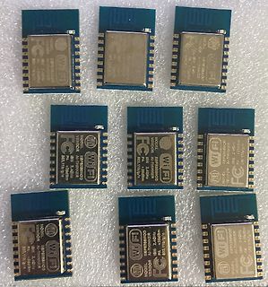
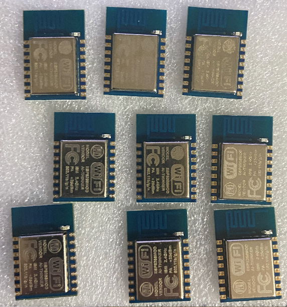
Mehrere ESP8266 WiFi Module
WiFi ESP8266MOD VENDOR: AI-THINKER MODEL: ESP8266MOD 2.4GHz 802.11b/g/n PA +20dBm FC
in „[V] ESP8266 Module“ · Markt · · Platinenfotos
-
Bild
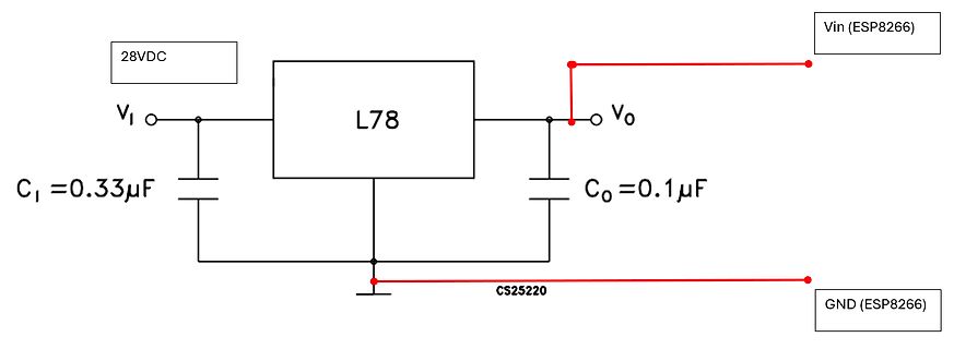
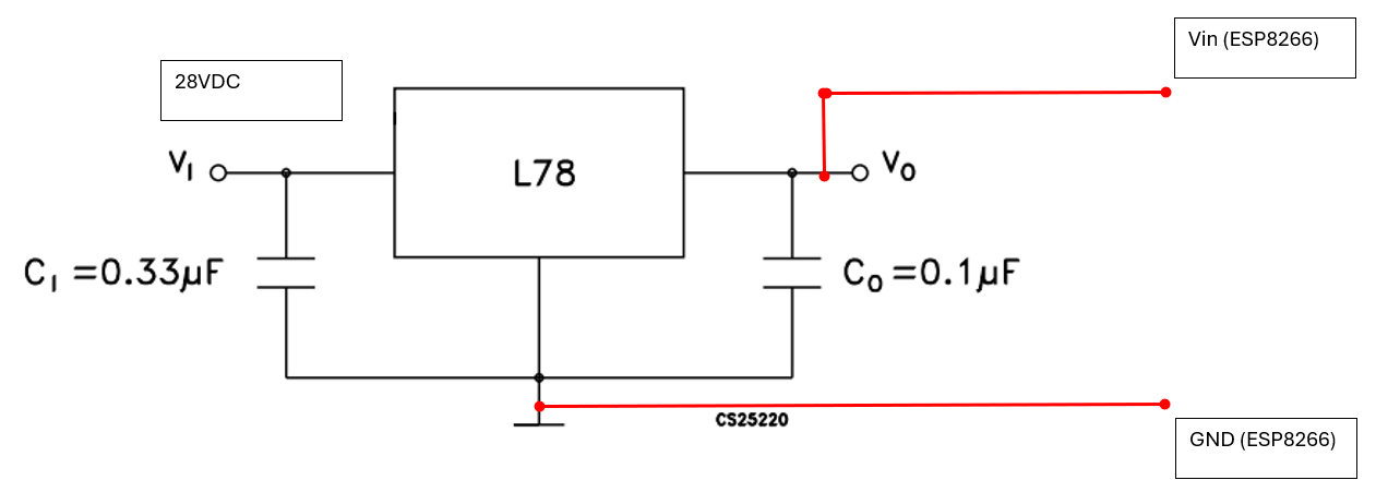
Schaltplan eines Spannungsreglers für ESP8266
28VDC L78 VI VO Vin (ESP8266) CI = 0.33µF CO = 0.1µF CS25220 GND (ESP8266)
in „ESP 8266 WiFi funktioniert nicht mit L 7805 CV Festspannungsregler“ · Mikrocontroller und Digitale Elektronik · · Schaltpläne
-
Bild
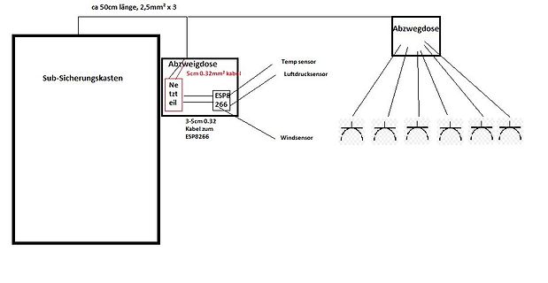
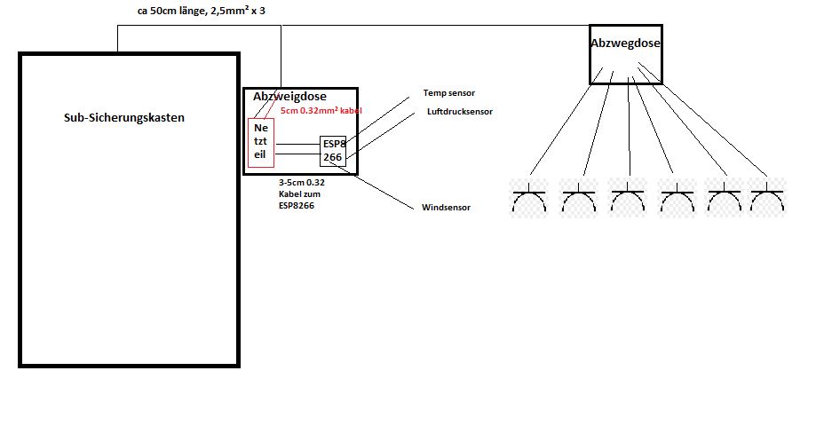
Skizze einer Verkabelung mit Sensoren und ESP8266
länge, 2,5mm² x 3 Sub-Sicherungskasten Abzweigdose Temp sensor Luftdrucksensor 5cm 0.32mm² kabel ESP8266 3-5cm 0.32 Kabel zum ESP8266 Windsensor Abzweigdose
in „Kabeldurchmesser bei Netzteil, Durchschnitt frage?“ · Analoge Elektronik und Schaltungstechnik · · Diagramme
-
PDF
esp8266player2-brd.pdf
D n - L u P H E D 3 L 2 t h e n e n A 19.01.2018 11:15:46 f=2.80 C:\Users\gau2hi\Documents\eagle\ESP8266\esp8266player2.brd
-
Datei
Test_ESP8266_DS18B20.ino
Santos Complete project details at https://RandomNerdTutorials.com https://randomnerdtutorials.com/esp8266-ds18b20-temperature-sensor-web-server-with-arduino-ide/ mit Sensor DS18B20 *********/ #include <Arduino.h> #include <ESP8266WiFi.h> #include <Hash.h> #include <ESPAsyncTCP.h> #include <ESPAsyncWebServer.h
in „HTML Anzeige - Farbe Meldetext ändern“ · Mikrocontroller und Digitale Elektronik ·
-
Datei
SPI_Interrupt.ino
//Add the SPI library so we can communicate with the ADXL345 sensor #include <ESP8266WiFi.h> #include <WiFiUdp.h> #include "Arduino.h" #include <SPI.h> //Assign the Chip Select signal to pin 5. int CS=5; int interruptPin=4; volatile int loopi = 0; struct dirs{ int x; int y; int z;
in „ADXL345 und ESP8266: Echtzeitdatenergassung mit konstanter Abtastrate und Interrupts“ · Mikrocontroller und Digitale Elektronik ·
-
Bild
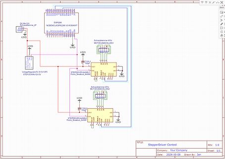
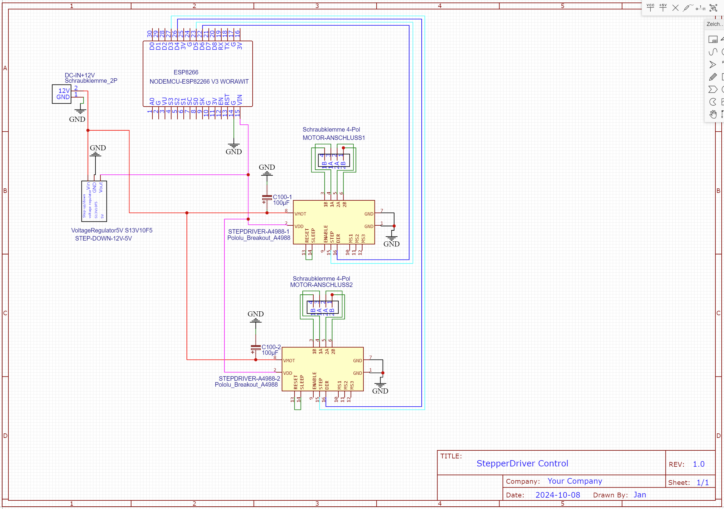
Schaltplan StepperDriver Control mit ESP8266
DC-IN +12V, ESP8266, NODEMCU-ESP8266 V3 WROOM, GND, VoltageRegulator 5V STEP-DOWN-12V-5V, C100-1 100uF, C100-2 100uF, STEPDRIVER-A4988-1 Pololu Breakout_A4988, STEPDRIVER-A4988-2 Pololu Breakout_A4988, MOTOR-ANSCHLUSS1
in „ESP8266 mit A4988 macht Probleme“ · Mikrocontroller und Digitale Elektronik · · Schaltpläne
-
Bild
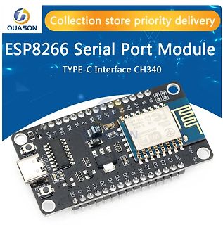
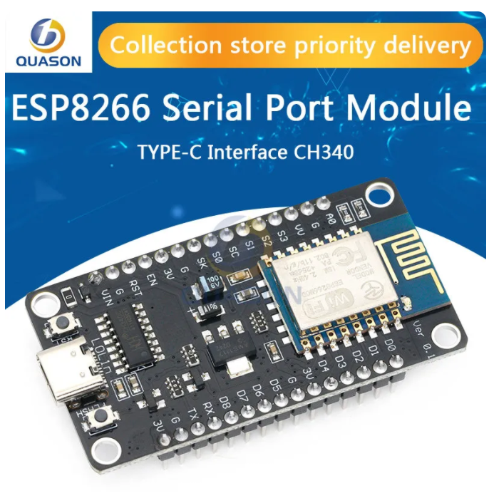
ESP8266 Serial Port Module mit Type-C Interface
QUASON Collection store priority delivery ESP8266 Serial Port Module TYPE-C Interface CH340 Ver. 0.1 ESP-12E WiFi MODEL ESP8266 CH340 G RX TX D6 D5 D4 D3 D2 D1 D0 G 3V G RX TX D6 D5 D4 D3 D2 D1 D0 G 3V G RST EN G UN JUN 5V USB TYPE-C
in „ESP01S findet BME280 nicht“ · Mikrocontroller und Digitale Elektronik · · Platinenfotos
-
Bild
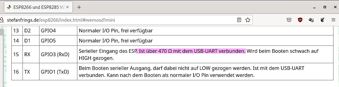
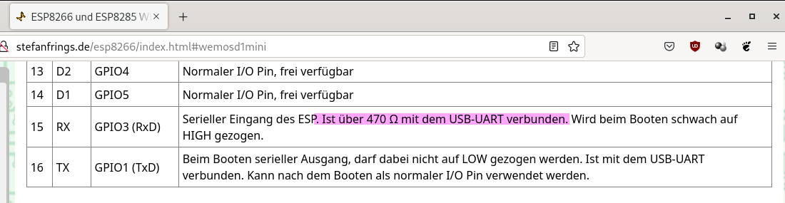
Tabelle der ESP8266 GPIO-Belegungen
ESP8266 und ESP8285 W... stefanfring.de/esp8266/index.html#wemosd1mini 13 D2 GPIO4 Normaler I/O Pin, frei verfügbar 14 D1 GPIO5 Normaler I/O Pin, frei verfügbar 15 RX GPIO3 (RxD) Serieller Eingang des ESP
in „Seltsames Phänomen bei serieller Übertr. ESP8266 - MBus 2. Versuch“ · Mikrocontroller und Digitale Elektronik · · Screenshots
-
Bild
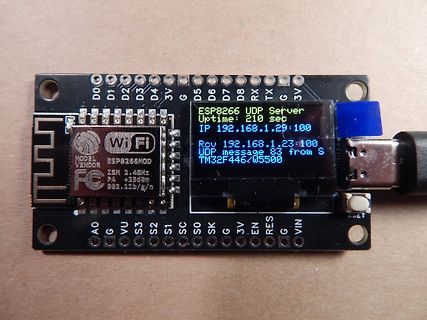
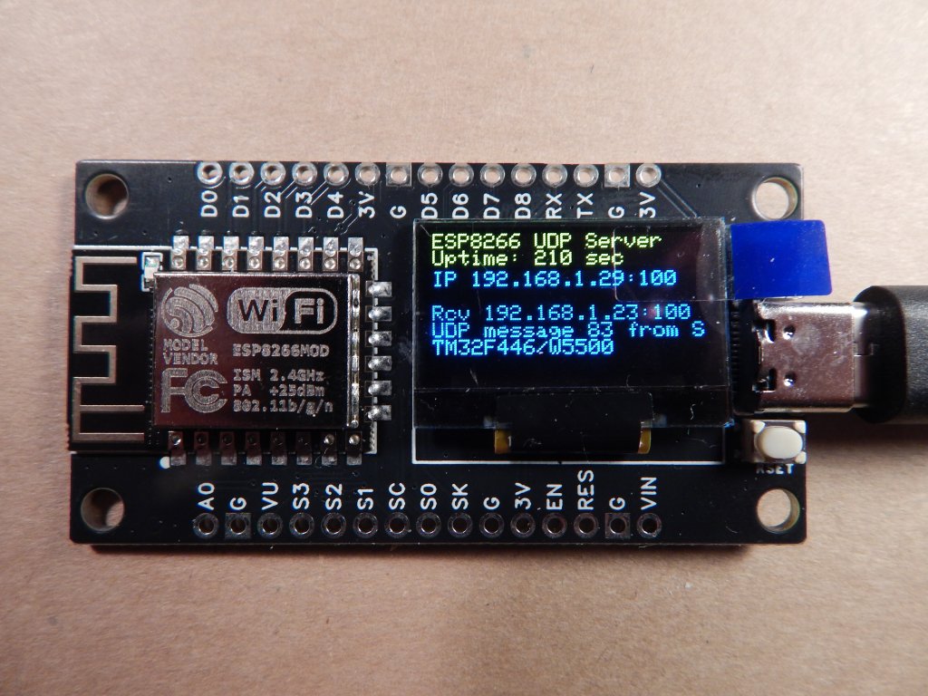
ESP8266 UDP Server auf Leiterplatte mit Display
D0 D1 D2 D3 3V G D5 D7 RX TX 3V ESP8266 UDP Server Uptime: 210 sec IP 192.168.1.29:100 Rec 192.168.1.23:100 UDP message 83 from S TM32F446/W5500 Wi-Fi MODEL VENDOR ESP8266MOD FC ISM 2.4GHz PA +20dBm 802.11b/g/n A0 G VU S3 S1 S0 G 3V EN
in „UDP-Netzwerke(l)n mit kleinen Mikrocontrollern und WizNet W5100/W5500“ · Mikrocontroller und Digitale Elektronik · · Platinenfotos
-
Bild
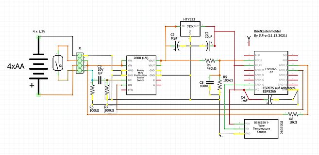
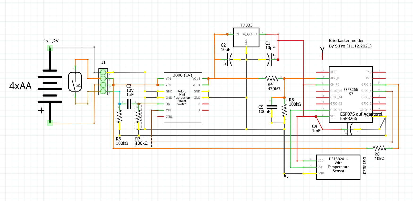
Schaltplan eines ESP8266-basierten Briefkastenmelders
1uF, R6 100k, R7 100k, CTRL, Briefkastenmelder By S.Fre (11.12.2021), R4 470k, R5 100k, C5 100nF, ESP8266 07, ESP07S auf Adapterpl. ESP8266, C4 1mF, R8 10k, DS18B20 1-Wire Temperature Sensor, DS18B20, VDD, DQ, GND
in „ESP8266 mit Selbsthaltung“ · Mikrocontroller und Digitale Elektronik · · Schaltpläne
-
Bild
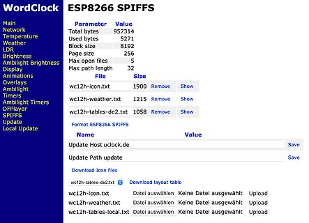
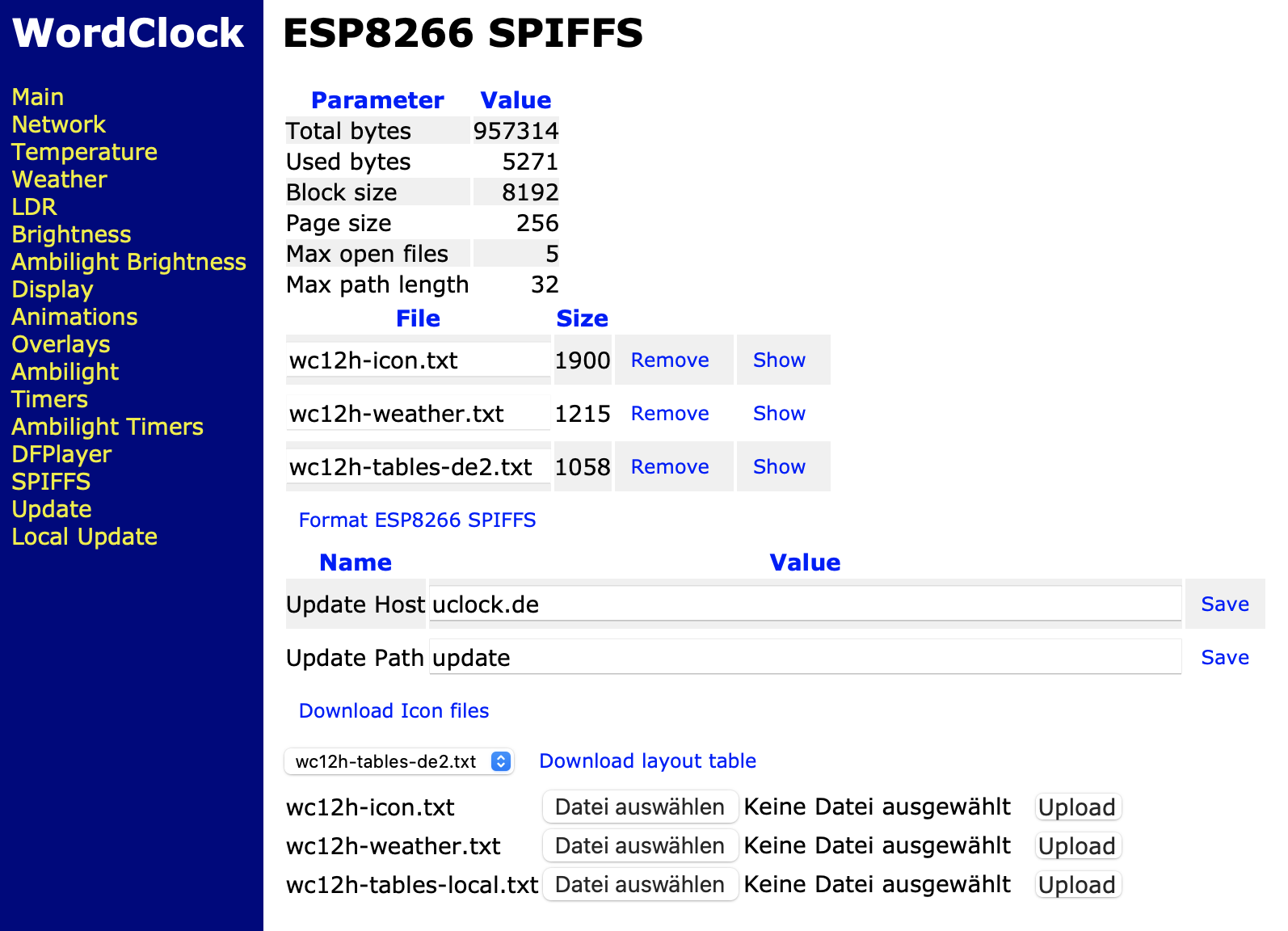
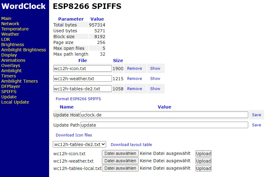
Webinterface ESP8266 SPIFFS Dateiverwaltung
WordClock ESP8266 SPIFFS Parameter Value Total bytes 957314 Used bytes 5271 Block size 8192 Page size 256 Max open files 5 Max path length 32 File Size wc12h-icon.txt 1900 Remove Show wc12h-weather.txt 1215 Remove Show wc12h-tables-de2.txt 1058 Remove Format ESP8266 SPIFFS Name Value Update Host uclock.de Save Update Path update Save Download Icon files wc12h-tables-de2.txt Download layout table wc12h-icon.txt Datei auswählen Keine Datei ausgewählt Upload wc12h-weather.txt
in „WordClock mit WS2812“ · Projekte & Code · · Screenshots
-
Bild
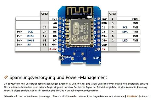
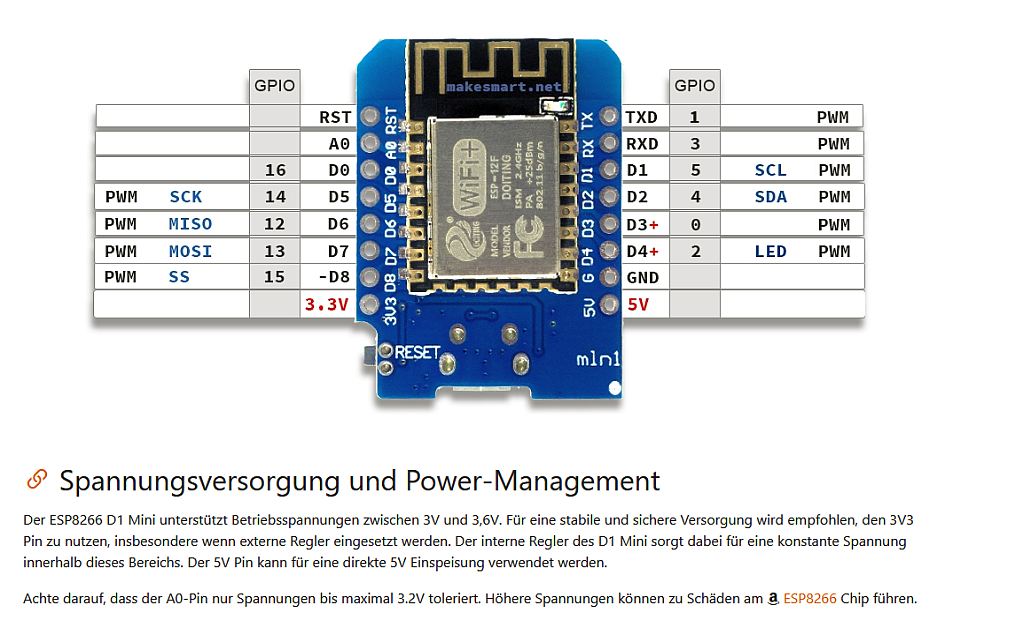
ESP8266 D1 Mini Pinbelegung und Spannungsversorgung
4 SDA D7 D4 2 LED SS -D8 6 D3 GND 3V3 5V RESET mlnl Spannungsversorgung und Power-Management Der ESP8266 D1 Mini unterstützt Betriebsspannungen zwischen 3V und 3,6V. Für eine stabile und sichere Versorgung empfohlen, den 3V3 Pin zu nutzen, insbesondere wenn externe Regler eingesetzt werden. Der interne
in „ESP8266 D1 Mini + Relaismodul: Relais bleibt bei D1 dauerhaft eingeschaltet“ · Mikrocontroller und Digitale Elektronik · · Screenshots
-
Bild
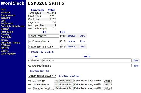
Webinterface ESP8266 SPIFFS Dateiverwaltung
WordClock ESP8266 SPIFFS Main Network Temperature Weather LDR Brightness Ambilight Brightness Display Animations Overlays Ambilight Timers Ambilight Timers DFPlayer SPIFFS Update Local Update Parameter Value Total
in „WordClock mit WS2812“ · Projekte & Code · · Screenshots
-
Datei
arduinopreferences.txt
boardsmanager.additional.urls=https://dl.espressif.com/dl/package_esp32_index.json,http://arduino.esp8266.com/stable/package_esp8266com_index.json build.verbose=true build.warn_data_percentage=75 cache.enable=true compiler.cache_core=true compiler.warning_level=all console=true console.auto_clear=true
in „Fehlersuche ESP32, der mit Hilfe der Arduino IDE programmiert wurd“ · Mikrocontroller und Digitale Elektronik ·
-
Datei
Test_ESP8266_DS18B20.ino
Santos Complete project details at https://RandomNerdTutorials.com https://randomnerdtutorials.com/esp8266-ds18b20-temperature-sensor-web-server-with-arduino-ide/ mit Sensor DS18B20 *********/ #include <Arduino.h> #include <ESP8266WiFi.h> #include <Hash.h> #include <ESPAsyncTCP.h> #include <ESPAsyncWebServer.h
in „HTML Anzeige - Farbe Meldetext ändern“ · Mikrocontroller und Digitale Elektronik ·
-
Datei
DTZ_Logger_OPEN.ino
OPEN (ohne Datenverschlüsselung des gesendeten Datenstromes) * 25.06.2021 P. Rebesky **/ #include <ESP8266WiFi.h> //ESP8266 Core WiFi Library #include <ESP8266WiFiMulti.h> //ESP8266 Core WiFi Library #include <DNSServer.h> #include <ESP8266WebServer.h> //Local WebServer #include "configDTZ.h" #include
in „DTZ541 mMe Datenlogger mit ESP (WEB-Sicht)“ · Mikrocontroller und Digitale Elektronik ·
-
Datei
MT174_Logger_OPEN.ino
Rebesky and any comercial use is forbidden without approval of us (me). **/ #define OTA_on #include <ESP8266WiFi.h> //ESP8266 Core WiFi Library #include <ESP8266WiFiMulti.h> //ESP8266 Core WiFi Library #include <DNSServer.h> #include <ESP8266WebServer.h> //Local WebServer #include "configDTZ.h" #include
in „Digitale Stromzähler auslesen und in DB speichern“ · Mikrocontroller und Digitale Elektronik ·
-
Bild
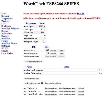
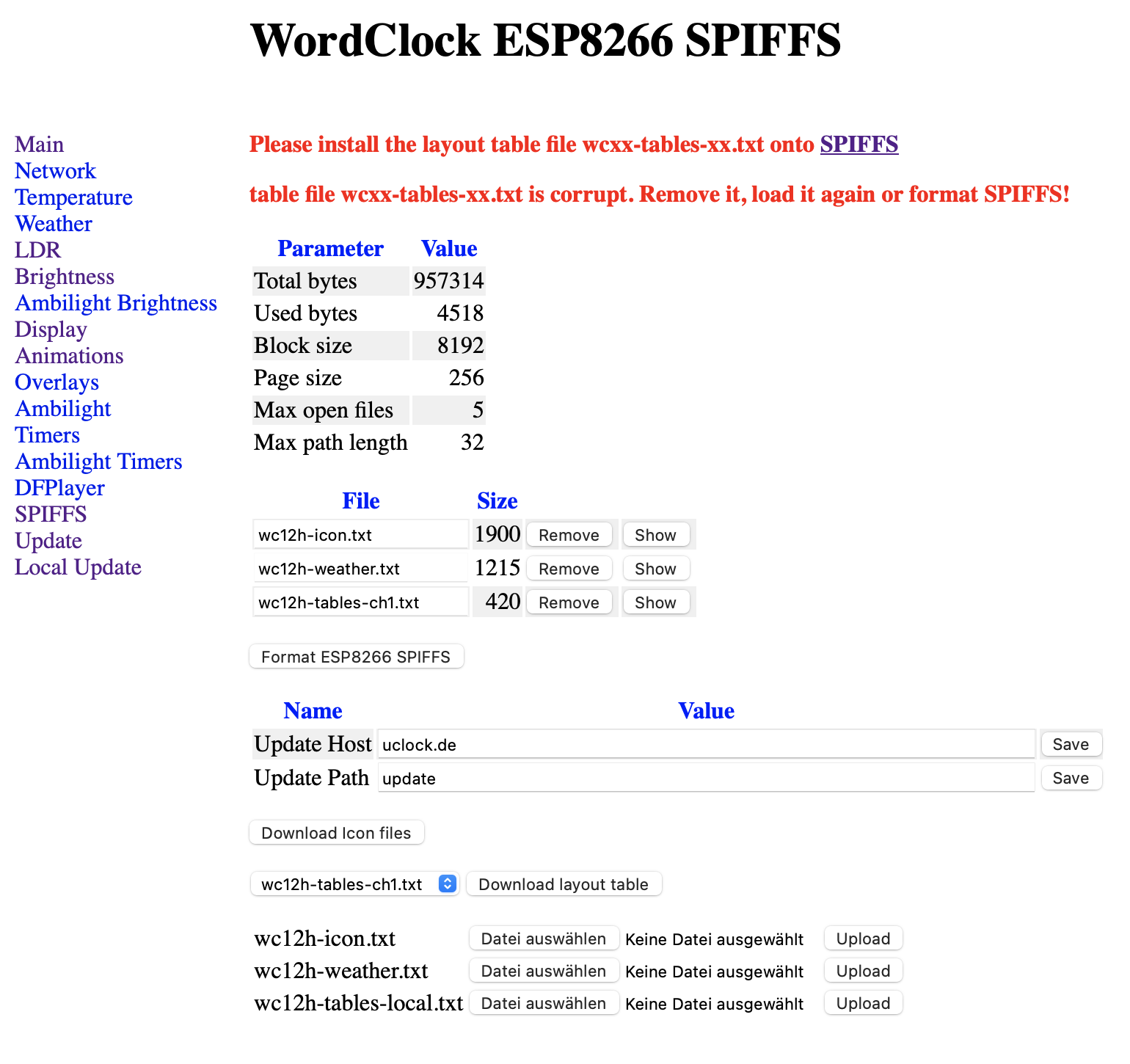
Webinterface für WordClock ESP8266 SPIFFS Dateiverwaltung
WordClock ESP8266 SPIFFS Please install the layout table file wcxx-tables-xx.txt onto SPIFFS table file wcxx-tables-xx.txt is corrupt. Remove it, load it again or format SPIFFS! Parameter Value LDR Total bytes 957314
in „WordClock mit WS2812“ · Projekte & Code · · Screenshots
-
Datei
WC12h_1n_284_20180221.txt
eeprom is online current eeprom version: 0x00020800 reading ir codes from eeprom DFPLAYER LOGGER ESP8266 LOGGER read rtc: We 2018-02-21 15:16:50 DFPlayer: SD card online DFPlayer: query software version DFPlayer: Version 0005 DFPlayer: set source device: 2 DFPlayer: set eq 0 DFPlayer: set volume 20 DFPlayer is up dfplayer is online RTC temperature: 19 esp8266 now up (- setup UDP) (- local port: 2421) (- setup server UDP) (- local port: 2424) (FIRMWARE 2.8.3a) read rtc: We 2018-02-21 15:17:45 RTC temperature: 19 read rtc: We 2018-02-21 15:18:45 RTC temperature
-
Bild
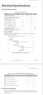
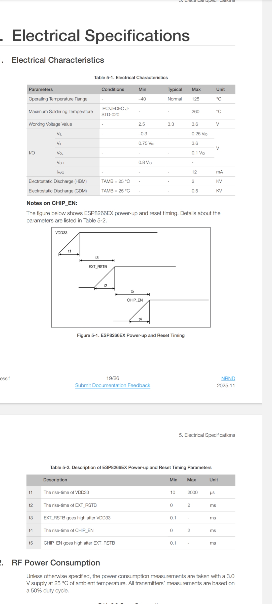
Ausschnitt aus einem Datenblatt mit elektrischen Spezifikationen
Discharge (HBM) TAMB = 25 °C 2 KV Electrostatic Discharge (CDM) TAMB = 25 °C 0.5 KV Figure 5-1. ESP8266EX Power-up and Reset Timing Table 5-2. Description of ESP8266EX Power-up and Reset Timing Parameters Description Min Max Unit t1 The rise-time of VDD33 10 2000 µs t2 The rise-time of EXT_RSTB 0 2
in „ESP8266 D1 Mini + Relaismodul: Relais bleibt bei D1 dauerhaft eingeschaltet“ · Mikrocontroller und Digitale Elektronik · · Screenshots
-
Bild
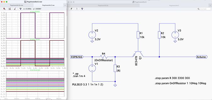
Schaltplan und Oszilloskop-Simulation in LTspice
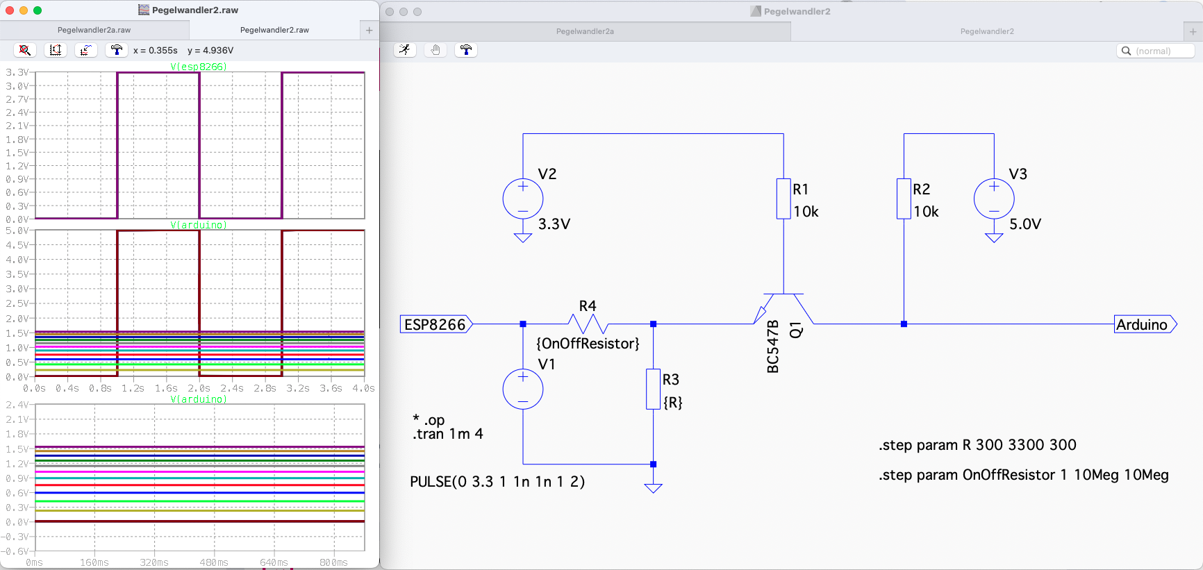
Pegelwandler2.raw Pegelwandler2 x = 0.355s y = 4.936V V(esp8266) 3.3V 3.0V 2.7V 1.0V 1.5V 1.2V 0.9V 0.6V 0.3V 0.0V 5.0V 4.5V 4.0V 3.5V 3.0V 2.5V 2.0V 1.5V 1.0V 0.5V 0.0V V(arduino) 2.4V 2.1V 1.8V 1.5V 1.2V 0.9V 0.6V 0.3V 0.0V -0.3V 0s 0.4s 0.8s 1.2s 1.6s 2.0s 2.4s 2.8s 3.2s 3.6s 4.0s 800ms 640ms 480ms 320ms 160ms 0s V2 3.3V R1 10k V3 5.0V R2 10k ESP8266 {OnOffResistor} R4 Q1 BC547 R3 {R} V1 Arduino .op .tran 1m 4 .step param R 300 3300 300 .step param OnOffResistor 1 10Meg 10Meg PULSE(0 3.3 1n 1n 1n 2)
in „NPN-Transistorschaltung "umdrehen"“ · Analoge Elektronik und Schaltungstechnik · · Screenshots
-
Datei
ESP8266_WifiDmx.ino
#include "Arduino.h" #include <ESP8266WiFi.h> #include <ESP8266WebServer.h> #include <ESPDMX.h> #include <EEPROM.h> /* debug request string on web page */ #define WEBSITE_DEBUG_REQUEST 0 /* pin definitions for LEDs and cfg-reset */ #define
in „FreeRTOS - ESP8266 "vergisst" Bytes beim Senden über SPI“ · Mikrocontroller und Digitale Elektronik ·
-
Datei
ESP8266_WifiDmx.c
#include "Arduino.h" #include <ESP8266WiFi.h> #include <ESP8266WebServer.h> #include <ESPDMX.h> #include <EEPROM.h> /* debug request string on web page */ #define WEBSITE_DEBUG_REQUEST 0 /* pin definitions for LEDs and cfg-reset */ #define
in „FreeRTOS - ESP8266 "vergisst" Bytes beim Senden über SPI“ · Mikrocontroller und Digitale Elektronik ·
-
Datei
esp8266_wifi_duck.ino
#include <ESP8266WiFi.h> #include <FS.h> #include <ESP8266mDNS.h> #include <ESPAsyncTCP.h> #include <ESPAsyncWebServer.h> #include <SPIFFSEditor.h> #include <EEPROM.h> #include "data.h" #include "Settings.h" #define
in „Arduino IDE Kompilierungsfehler“ · Mikrocontroller und Digitale Elektronik ·
-
PDF
Projektuebersicht_ESP8266_Wassermelder.pdf
Wassermelder mit ESPHome und Homeassistant Problembeschreibung: Wenn die Sonde im Wasser liegt, wechselt der ESP-01 nicht zuverlässig seinen Status. Nur wenn man die Sonde tief ins Wasser eintaucht, erfolgt der Zustandswechsel am ESP-01. Spannungsmessung zwischen GND und GPIO2 ergab: - Sonde nicht im Wasser (Zustand „trocken“): U=3,12 V - Sondenkontakte galvanisch kurzgeschlossen (soll Zustand „nass“ simulieren): U=0 V, blaue LED an GPIO2 leuchtet - Sonde im Wasser und eingetaucht: U=1,54 V (diese Spannung scheint der Schwellwert zwischen den beiden Zuständen „nass“ und „trocken“ zu sein. Bild
in „ESP8266 Wassermelder ESPHome Homeassistant“ · Mikrocontroller und Digitale Elektronik ·
-
Bild
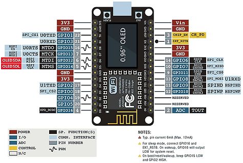
Pinbelegung eines ESP8266 Moduls mit OLED Display
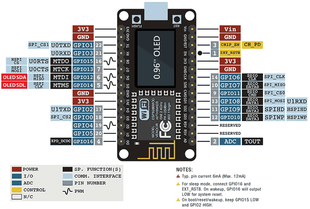
HSPIPI GPIO0 18 GPIO5 20 GPIO10 SDIO DATA1 SPIWP HSPIWP U1RXD SPI_CS2 GPIO2 17 D4 D3 D2 D1 D0 0 Wi-Fi ESP8266MOD AUTHINKER MODEL VENDOR FC NOTES: Typ. pin current 6mA (Max. 12mA) For sleep mode, connect GPIO16 and EXT_RST. On wakeup, GPIO16 will output LOW for system reset. On boot/reset/wakeup, keep GPIO15
in „NodeMCU ESP8266 Entwicklungsboard 0.96'' OLED Display für Arduino/Micropython“ · Mikrocontroller und Digitale Elektronik · · Screenshots
-
Datei
ESP8266_WiFiClient.ino
#include <ESP8266WiFi.h> #include <lwip/icmp.h> #include <lwip/raw.h> const char* ssid = "x"; const char* password = "y"; u8_t packedReceived(NULL, raw_pcb * pcb, pbuf * packetBuffer, const ip_addr_t * addr) { Serial.println
in „Wie kann man mit ESP8266/ArduinoIDE auf IP-Pakete zugreifen?“ · Mikrocontroller und Digitale Elektronik ·
-
Datei
ESP8266_WiFiClient.ino
#include <ESP8266WiFi.h> #include <lwip/icmp.h> #include <lwip/raw.h> const char* ssid = "x"; const char* password = "y"; u8_t packedReceived(void* arg, raw_pcb * pcb, pbuf * packetBuffer, const ip_addr_t * addr){
in „Wie kann man mit ESP8266/ArduinoIDE auf IP-Pakete zugreifen?“ · Mikrocontroller und Digitale Elektronik ·
-
Datei
partlist.txt
Partlist Exported from esp8266.brd at 15.09.16 19:38 EAGLE Version 7.6.0 Copyright (c) 1988-2016 CadSoft Assembly variant: Part Value Package Library Position (mm) Orientation C1 10uF E2,5-6 rcl (20.955 11.43) R270 C2 100uF E2,5
-
PDF
Log_12h.pdf
eeprom is online current eeprom version: 0x00020900 reading ir codes from eeprom DFPLAYER LOGGER ESP8266 LOGGER read rtc: Sa 2019-01-26 15:16:05 read rtc: Sa 2019-01-26 15:16:05 DFPlayer: SD card online DFPlayer: query software version DFPlayer: Version 0008 DFPlayer: set source device: 2 DFPlayer: set eq 0 DFPlayer: set volume 0 DFPlayer is up dfplayer is online esp8266 now up (- setup UDP) (- local port: 2421) (- setup server UDP) (- local port: 2424) (FIRMWARE 2.9.2) (- tables found; wc12h-tables-de.txt) (- check tables successful) --> tabinfo<0d><0a> --> tabillu
-
Datei
main.cpp
PCF_INPUT3 1 #define PCF_INPUT4 0 #define INPUT_CHECK_INTERVAL 10 PCF857x pcf8574(0x20, &Wire); esp8266::polledTimeout::oneShotFastMs debounceTime(PCF_DEBOUNCE_MS); esp8266::polledTimeout::periodicFastMs checkInputs(INPUT_CHECK_INTERVAL); uint8_t pins = 0; void setup() { Serial.begin(115200); pinMode
in „ESP8266 mit PCF8574 und Taster - Interrupt vom PCF "spinnt"?“ · Mikrocontroller und Digitale Elektronik ·
-
Datei
esp8266_bme280_unfluxdb_code.txt
#include <Adafruit_Sensor.h> #include <Adafruit_BME280.h> #include <InfluxDbClient.h> #include <ESP8266WiFi.h> Adafruit_BME280 bme; float temperature, humidity, pressure; // InfluxDB server url, e.g. http://192.168.1.48:8086 (don't use localhost, always server name or ip address) #define INFLUXDB_URL
in „ESP8266 BME280 InfluxDB Daten kommen nicht an“ · Mikrocontroller und Digitale Elektronik ·
-
Datei
DTZ_Logger_OPEN.ino
by Peter Rebesky and any comercial using is forbidden without approval of us (me). **/ #include <ESP8266WiFi.h> //ESP8266 Core WiFi Library #include <ESP8266WiFiMulti.h> //ESP8266 Core WiFi Library #include <DNSServer.h> #include <ESP8266WebServer.h> //Local WebServer #include "configDTZ.h" #include
in „DTZ541 mMe Datenlogger mit ESP (WEB-Sicht)“ · Mikrocontroller und Digitale Elektronik ·
-
Datei
DTZ_Logger_OPEN.ino
by Peter Rebesky and any comercial using is forbidden without approval of us (me). **/ #include <ESP8266WiFi.h> //ESP8266 Core WiFi Library #include <ESP8266WiFiMulti.h> //ESP8266 Core WiFi Library #include <DNSServer.h> #include <ESP8266WebServer.h> //Local WebServer #include "configDTZ.h" #include
in „DTZ541 mMe Datenlogger mit ESP (WEB-Sicht)“ · Mikrocontroller und Digitale Elektronik ·
-
Datei
DTZ_Logger_OPEN.ino
by Peter Rebesky and any comercial using is forbidden without approval of us (me). **/ #include <ESP8266WiFi.h> //ESP8266 Core WiFi Library #include <ESP8266WiFiMulti.h> //ESP8266 Core WiFi Library #include <DNSServer.h> #include <ESP8266WebServer.h> //Local WebServer #include "configDTZ.h" #include
in „Digitale Stromzähler auslesen und in DB speichern“ · Mikrocontroller und Digitale Elektronik ·
-
Datei
Mixed_Reality_Space_Forum.txt
#include <ESP8266WiFi.h> #include <PubSubClient.h> #include <SPI.h> #include <Ethernet.h> #include <PubSubClient.h> #include <MPU6050_tockn.h> #include <Wire.h> MPU6050 mpu6050(Wire); const char* ssid = ""; const char
in „char in int umwandeln“ · Mikrocontroller und Digitale Elektronik ·
-
PDF
fcc_3.pdf
modular have buffered modulation/data inputs. buffered data inputs stage has been integrated in “chip ESP8266”. 3. The modular transmitter must have its own power supply regulation Note: power supply regulation has been integrated in “chip ESP8266”. 4. The modular transmitter must comply with the antenna

in „Wlan2Serial Modul für 5 euro“ · Mikrocontroller und Digitale Elektronik ·
-
Datei
Arduino-ESP-Klingel-Skript_mit_mqtt_kw_letzte_geflashte_Version.ino
#include <Arduino.h> #include <ESP8266WiFi.h> #include <ESP8266HTTPClient.h> #include <tr064.h> #include <WiFiClient.h> const char WIFI_SSID[] = ""; // <-- ändern const char WIFI_PASSWORD[] = ""; // <-- ändern const char USER[] = ""; /
in „ESP8266 Klingel MQTT - Batterie dauernd alle“ · Haus & Smart Home ·