-
Datei
dude54arduino.txt
0x41 = ATMEGA103 Device code: 0x42 = (unknown) Device code: 0x43 = ATMEGA128 Device code: 0x44 = (unknown) Device code: 0x45 = ATMEGA64 Device code: 0x46 = (unknown) Device code: 0x47 = (unknown) Device code: 0x48
in „avrdude - Probleme unter Mac OS X 10.7 (Lion)“ · Mikrocontroller und Digitale Elektronik ·
-
Datei
stk500boot.c
__) #define SIGNATURE_BYTES 0x1E9406 #elif defined (__AVR_ATmega128__) #define SIGNATURE_BYTES 0x1E9702 #elif defined (__AVR_AT90CAN32__) #define SIGNATURE_BYTES 0x1E9581 #elif defined (__AVR_AT90CAN64__) #define SIGNATURE_BYTES 0x1E9681 #elif defined (__AVR_AT90CAN128
in „STK500v2-Bootloader von Peter Fleury“ · Projekte & Code ·
-
PDF
Oszilloskop_mit_LCD_3_Forum.pdf
Long time Oscilloskop with Atmega32 & LCD-Display 128x64 Pixel Einleitung: Das preiswerte Display LCD DM19264A (Pollin) (Siehe auch http://www.mikrocontroller.net/topic/217600 ) führte zu meinem bisher größten Projekt mit ATmega-Microcontrollern
in „Long time Oscilloskop with Atmega32 & LCD-Display 128x64 Pixel“ · Mikrocontroller und Digitale Elektronik ·
-
Datei
Projet_07_Akkulader.asm
nicht gesetzt ;ADPS2:= -bit wird 111 gewählt weil ich den prescaler select -bit auf divisionsfaktor 128 brauche ;(siehe tabelle S.205 datenblätter atmega8) ;Der ADC benötigt einen eigenen Takt, welchen er sich selber aus der CPU-Taktfreqenz erzeugt. Der ADC-Takt sollte zwischen 50 und 200kHz sein. ;Der
in „Wichtig: was ist hier im AVR programm falsch??“ · Mikrocontroller und Digitale Elektronik ·
-
PDF
DOG_readme.pdf
Grafische Darstellungen auf dem Display DOG 128x64 Nach dem Motto " Es ist zwar schon alles gesagt, aber noch nicht von jedem" will ich hier meinen Exkurs in das Thema "Grafische Darstellungen auf den Display DOG128x64" beisteuern. Beim Einstieg
in „Grafikausgabe auf dem LCD-Grafikmodul DOG 128x64 für M88 in C“ · Projekte & Code ·
-
Datei
ePaper-Test2.ino
display.drawPagedToWindow(pfeil, 0, 0, 56, 17, GxEPD_BLACK); //geht nicht display.drawBitmap(grund, 128-56, 0, 56, 296, GxEPD_WHITE); display.drawBitmap(pfeil, 128-56, 0, 56, 17, GxEPD_WHITE); display.updateWindow(128-56, 0, 56, 296); // Display aktualisieren // bis hier funktioniert es einwandfrei delay(1000); } void loop() { for (uint16_t r = 0; r < 279; r=r+11) { display.drawBitmap(grund, 128-56, 0, 56, 296, GxEPD_WHITE); display.drawBitmap(pfeil, 128-56, r, 56, 17, GxEPD_WHITE); display.updateWindow(128-56, 0, 56, 296); // Display aktualisieren /* hier fangen die Probleme an: * - bei jedem
in „Arduino-Library auf GitHub: Keine Dokumentation?“ · Mikrocontroller und Digitale Elektronik ·
-
Datei
stk500boot.c
__) #define SIGNATURE_BYTES 0x1E9406 #elif defined (__AVR_ATmega128__) #define SIGNATURE_BYTES 0x1E9702 #elif defined (__AVR_ATmega2561__) #define SIGNATURE_BYTES 0x1E9802 #elif defined (__AVR_AT90CAN32__) #define SIGNATURE_BYTES 0x1E9581 #elif defined (__AVR_AT90CAN64
in „[AVR] Problem mit ATmega2561 und Fleury Bootloader“ · Mikrocontroller und Digitale Elektronik ·
-
Datei
I2C.cpp
pull-ups for twi // as per note from atmega128 manual pg204 sbi(PORTD, 0); sbi(PORTD, 1); #endif } else { #if defined(__AVR_ATmega168__) || defined(__AVR_ATmega8__) || defined(__AVR_ATmega328P__) // deactivate internal pull-ups for twi // as per note from atmega8 manual pg167 cbi(PORTC, 4); cbi(PORTC, 5); #else // deactivate internal pull-ups for twi // as per note from atmega128 manual pg204 cbi(PORTD, 0); cbi(PORTD, 1); #endif } } /////////////carry over
in „BMA020 Selftest_1 Interrupt probleme“ · Mikrocontroller und Digitale Elektronik ·
-
Datei
USART.h
error "F_CPU not defined" #endif //F_CPU //Anpassen der seriellen Schnittstellen Register wenn ein ATMega128 benutzt wird #if defined (__AVR_ATmega128__) #define USR UCSR0A #define UCR UCSR0B #define UDR UDR0 #define UBRR UBRR0L #define USART_RX USART0_RX_vect #endif #if defined (__AVR_ATmega644__) ||
in „#define (wie kann ich vektor erstellen.“ · Mikrocontroller und Digitale Elektronik ·
-
Datei
TMC222_AVR.h
library for using a TMC222 together with AVR processors that have a hardware TWI interface (e.g. ATmega8, ATmega48, ATmega88, ATmega168, ATmega16, ATmega32, ATmega64, ATmega128, AT90CAN128 and many more). It implements and interrupt driven TWI master communication over the TWI of the AVR MCU and utilizes
in „Ansteuerung TMC222“ · Mikrocontroller und Digitale Elektronik ·
-
Datei
atmega32u2.patch
-08 22:14:49.018155272 +0100 @@ -4199,6 +4199,70 @@ }, { 0 }, // Xmega device descr. }, + // DEV_ATMEGA32U2 + // Get these data from the AVRStudio-Installation + // Atmel/AVR Tools/Partdescriptionfiles + { + "atmega32u2", + 0x958A, + 128, 256, // 32768 bytes flash + 4, 256, // 1024 bytes EEPROM + 29
in „avarice und atmega32u2“ · Mikrocontroller und Digitale Elektronik ·
-
Datei
usart.h
define F_CPU 14745600UL #endif //SYSCLK //Anpassen der seriellen Schnittstellen Register wenn ein ATMega128 benutzt wird #if defined (__AVR_ATmega128__) #define USR UCSR0A #define UCR UCSR0B #define UDR UDR0 #define UBRR UBRR0L #define USART_RX USART0_RX_vect #endif #if defined (__AVR_ATmega644__) ||
in „µSD Karte Ulrich Radig Code funktioniert nicht mehr“ · Mikrocontroller und Digitale Elektronik ·
-
Datei
usart.h
define F_CPU 14745600UL #endif //SYSCLK //Anpassen der seriellen Schnittstellen Register wenn ein ATMega128 benutzt wird #if defined (__AVR_ATmega128__) #define USR UCSR0A #define UCR UCSR0B #define UDR UDR0 #define UBRR UBRR0L #define USART_RX USART0_RX_vect #endif #if defined (__AVR_ATmega644__) ||
in „SD-Karte mit Mega644 & Software von Ulrich Radig“ · Mikrocontroller und Digitale Elektronik ·
-
Datei
xnutboot.c
be written into the baudrate register. Consult your * AVR data sheet for the correct value. On an ATmega128 running at * 14.7456 MHz a value of 7 will result in 115200 bps. */ #define BAUDRATE_FACTOR 25 /* * Maximum number of consecutive protocol errors until we give up. */ #define MAX_PROTO_ERRORS 10
in „Bootloader auf Basis des xnutboot Problem“ · Mikrocontroller und Digitale Elektronik ·
-
Datei
xnutboot.c
be written into the baudrate register. Consult your * AVR data sheet for the correct value. On an ATmega128 running at * 14.7456 MHz a value of 7 will result in 115200 bps. */ #define BAUDRATE_FACTOR 7 /* * Maximum number of consecutive protocol errors until we give up. */ #define MAX_PROTO_ERRORS 10
in „AVR Bootloader (Basis: xnutboot) Problem bei Programmübertragung“ · Mikrocontroller und Digitale Elektronik ·
-
Datei
xnutboot.c
be written into the baudrate register. Consult your * AVR data sheet for the correct value. On an ATmega128 running at * 14.7456 MHz a value of 7 will result in 115200 bps. */ #define BAUDRATE_FACTOR 7 /* * Maximum number of consecutive protocol errors until we give up. */ #define MAX_PROTO_ERRORS 10
in „CRC-16 Implementierung unverständlich“ · Mikrocontroller und Digitale Elektronik ·
-
Datei
xnutboot.c
be written into the baudrate register. Consult your * AVR data sheet for the correct value. On an ATmega128 running at * 14.7456 MHz a value of 7 will result in 115200 bps. */ #define BAUDRATE_FACTOR 7 /* * Maximum number of consecutive protocol errors until we give up. */ #define MAX_PROTO_ERRORS 10
in „Zeitproblem beim AVR-Flashen via XMODEM“ · Mikrocontroller und Digitale Elektronik ·
-
Datei
xnutboot_1281.c
be written into the baudrate register. Consult your * AVR data sheet for the correct value. On an ATmega128 running at * 14.7456 MHz a value of 7 will result in 115200 bps. */ #define BAUDRATE_FACTOR 25 /* * Maximum number of consecutive protocol errors until we give up. */ #define MAX_PROTO_ERRORS 10
in „Zeitproblem beim AVR-Flashen via XMODEM“ · Mikrocontroller und Digitale Elektronik ·
-
Datei
usart.h
define SYSCLK 16000000UL #endif //SYSCLK */ //Anpassen der seriellen Schnittstellen Register wenn ein ATMega128 benutzt wird #if defined (__AVR_ATmega128__) #define USR UCSR0A #define UCR UCSR0B #define UDR UDR0 #define UBRR UBRR0L #define USART_RX USART0_RX_vect #endif #if defined (__AVR_ATmega644__) ||
in „Empfangen über UART mit ATmega32“ · Mikrocontroller und Digitale Elektronik ·
-
Datei
twitest.c
* * Simple demo program that talks to a 24Cxx I²C EEPROM using the * builtin TWI interface of an ATmega device. */ #include <inttypes.h> #include <stdio.h> #include <stdlib.h> #include <avr/io.h> #include <util/twi.h> /* Note [1] */ #define DEBUG 1 /* * System clock in Hz. */ #define F_CPU 14745600UL /* Note [2] */ /* * Compatibility defines. This should work on ATmega8, ATmega16, * ATmega163, ATmega323 and ATmega128 (IOW: on all devices that * provide a builtin TWI interface). * * On the 128, it defaults to USART 1. */ #ifndef UCSRB # ifdef UCSR1A /* ATmega128 *
in „Die I2C Schnittstelle eines PIC16F876A initialisieren“ · Mikrocontroller und Digitale Elektronik ·
-
Datei
Arduino_wdt.h
times will be as large as three times when operating at Vcc = 3 V, while the newer devices (e. g. ATmega128, ATmega8) only experience a negligible change. Possible timeout values are: 15 ms, 30 ms, 60 ms, 120 ms, 250 ms, 500 ms, 1 s, 2 s. (Some devices also allow for 4 s and 8 s.) Symbolic constants are
in „aktuelle AVR µC - wdt.h - kein RAMPD / CTRL / Enable Bit“ · Mikrocontroller und Digitale Elektronik ·
-
Datei
max31865.c
macro #define DDR(x) (*(&x - 1)) // address of data direction register of port x #if defined(__AVR_ATmega64__) || defined(__AVR_ATmega128__) /* on ATmega64/128 PINF is on port 0x00 and not 0x60 */ #define PIN(x) ( &PORTF==&(x) ? _SFR_IO8(0x00) : (*(&x - 2)) ) #else #define PIN(x) (*(&x - 2)) // address
in „Probleme mit MAX31865, Wert zu klein“ · Mikrocontroller und Digitale Elektronik ·
-
PDF
Amadeus.pdf
ATtiny11 High-voltage serial programming ATtiny12 High-voltage serial programming only - Tested ATmega8 xxx ATmega16 Not Tested ATmega32 xxx ATmega64 Tested ATmega128 Not Tested PIC12F629 Not Tested PIC12F675 Tested PIC16F630 Not Tested PIC16F676 Not Tested PIC18F242 Tested PIC18F248 Not Tested PIC18F252
in „USB-Programmer für eine Reihe von PICs und AVRs“ · Mikrocontroller und Digitale Elektronik ·
-
Datei
stk500boot.c
__) #define SIGNATURE_BYTES 0x1E9306 #elif defined (__AVR_ATmega8535__) #define SIGNATURE_BYTES 0x1E9308 #elif defined (__AVR_ATmega162__) #define SIGNATURE_BYTES 0x1E9404 #elif defined (__AVR_ATmega128__) #define SIGNATURE_BYTES 0x1E9702 #elif defined (__AVR_ATmega1280
in „[AVR] Register R0 und R1 direkt in C oder Inline Assembler“ · Mikrocontroller und Digitale Elektronik ·
-
Datei
out.txt
C:\Beispiele\gcctest1>make set -e; avr-gcc -MM -mmcu=atmega128 -I. -g -Os -funsigned-char -funsigned-bitfie lds -fpack-struct -fshort-enums -Wall -Wstrict-prototypes -Wa,-adhlns=gcctest1.l st -std=gnu99 gcctest1.c \ | sed 's,\(.*\)\.o[ :]*,\1.o \1.d : ,g' >
in „Clock skew detected“ · Mikrocontroller und Digitale Elektronik ·
-
Datei
atmega32u2.patch
-10 21:47:45.259999715 +0100 @@ -4333,6 +4333,72 @@ }, { 0 }, // Xmega device descr. }, + // DEV_ATMEGA32U2 + // Get these data from the AVRStudio-Installation + // Atmel/AVR Tools/Partdescriptionfiles + { + "atmega32u2", + 0x958A, + 128, 256, // 32768 bytes flash + 4, 256, // 1024 bytes EEPROM + 29
in „avarice und atmega32u2“ · Mikrocontroller und Digitale Elektronik ·
-
Datei
usart.h
define SYSCLK 12000000UL #endif //SYSCLK //Anpassen der seriellen Schnittstellen Register wenn ein ATMega128 benutzt wird #if defined (__AVR_ATmega128__) #define USR UCSR0A #define UCR UCSR0B #define UDR UDR0 #define UBRR UBRR0L #define USART_RX USART0_RX_vect #endif #if defined (__AVR_ATmega644__) #define
in „Funk-uhr über AVR Programmieren mit DCF01“ · Mikrocontroller und Digitale Elektronik ·
-
PDF
Amadeus.pdf
ATmega325 Not Tested* ATmega3250 Not Tested* ATmega329 Not Tested* ATmega3290 Not Tested* ATmega64 Tested ATmega645 Not Tested* ATmega6450 Not Tested* ATmega649 Not Tested* ATmega6490 Not Tested* ATmega128
in „USB-Programmer PIC/AVR Jetzt auch auf Deutsch :-)“ · Mikrocontroller und Digitale Elektronik ·
-
Datei
hsb2rgb.asm
------------------------------------------- ;HSB -> RGB Wandler, in AVR-Assembler, für ATiny und ATmega ;Kurzfeatures: (Details und ausführliche Erläuterungen im Quelltext) ;------------------------------------------------------------------- ;*Codegrösse nur ca.300 Words auf Atiny, ca.280 auf ATmega
in „Fertig: HSB->RGB Umrechnung rein in Assembler, auch für ATiny“ · Projekte & Code ·
-
PDF
Tut_Programmierung_Teil_1_Studio_6.pdf
Speicherortes (Verzeichnis) 3 Mit OK bestätigen Im nächsten Bild wählt man einen Prozessor aus. z.B. den ATmega 128 4 Weiter geht es mit OK Programmierung Nibo 2 – Teil 1 - AVR Studio 6 4 Es erscheint dieses Fenster. Hier kann der C-Code einge- geben werden. Es wird bereits ein kur- zer Code vorgegeben. Danach
in „AVR Studio 6 und Nibo 2“ · Mikrocontroller und Digitale Elektronik ·
-
Datei
USI_TWI_Slave.h
USI_START_vect #define USI_OVERFLOW_VECTOR USI_OVF_vect #endif #if defined(__AT90Mega165__) | defined(__ATmega165__) | \ defined(__ATmega325__) | defined(__ATmega3250__) | \ defined(__ATmega645__) | defined(__ATmega6450__) | \ defined(__ATmega329__) | defined(__ATmega3290__) | \ defined(__ATmega649__) | defined(__ATmega6490__) #define DDR_USI DDRE #define PORT_USI PORTE #define PIN_USI PINE #define PORT_USI_SDA PORTE5 #define PORT_USI_SCL PORTE4 #define PIN_USI_SDA PINE5 #define PIN_USI_SCL PINE4 #define USI_START_COND_INT
in „AVR: I2C bleibt hängen“ · Mikrocontroller und Digitale Elektronik ·
-
PDF
doc8002.pdf
Grouped by oscillator version. Oscillator Device RC oscillator CKDIV CLKPR version frequency [MHz] 2.0 ATmega163 1.0 - - 3.0 ATmega16 1.0, 2.0, 4.0, and 8.0 - - (1) (2) 3.1 ATmega128 1.0, 2.0, 4.0, and 8.0 - XDIV 4.0 ATmega169 8.0 Yes Yes 5.0 ATmega169P 8.0 Yes Yes Notes: 1. The ATmega103 Compatible Mode fuse
in „Genauigkeit interner Oszillator Mega8 ...“ · Mikrocontroller und Digitale Elektronik ·
-
Datei
header_lcd.h
#define DDR(x) (*(&x - 1)) /* address of data direction register of port x */ #if defined(__AVR_ATmega64__) || defined(__AVR_ATmega128__) /* on ATmega64/128 PINF is on port 0x00 and not 0x60 */ #define PIN(x) ( &PORTF==&(x) ? _SFR_IO8(0x00) : (*(&x - 2)) ) #else #define PIN(x) (*(&x - 2)) /* address
in „Display defekt? Zeilen werden nicht angezeigt..“ · Mikrocontroller und Digitale Elektronik ·
-
Datei
Impuls-41-Therm.txt
Thermotronic-orig.Software mit Danfoss-Ventil hpk41 Helmut.P Reflexschrankenimpulse an X.2 ausgekoppelt und mit zus.ATMega8 gezählt und die impulslänge(ms) über 8 Impulse aufsummiert. Die große Impulslänge der ersten 8 Impulse nach den jeweiligen Motorstarts ist im Programm des ATMega erzeugt! Die Grenze wird aus der Länge
in „Preisgünstiger Heizungsregler bei Praktiker“ · Mikrocontroller und Digitale Elektronik ·
-
Datei
Fehlermeldungen.txt
atmega644 -I. -g -Os -funsigned-char -funsigned-bitfields -fpack-struct -fshort-enums -Wall -Wstrict-prototypes -Wa,-adhlns=wol.lst -std=gnu99 wol.c -o wol.o Compiling: http_get.c avr-gcc -c -mmcu=atmega644
in „GCC: wie kompiliere ich ETH_M32EX von Ulrich Radig richtig?“ · Mikrocontroller und Digitale Elektronik ·
-
 Bild
Bild
Software Update Liste mEDBG_TP nEDBG_TP
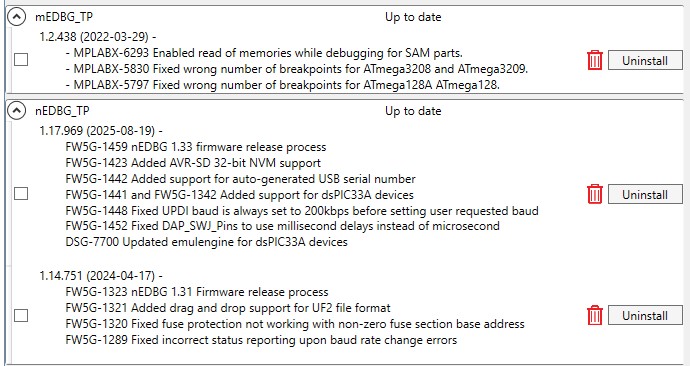
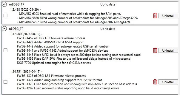
read of memories while debugging for SAM parts. - MPLABX-5830 Fixed wrong number of breakpoints for ATmega3208 and ATmega3209. - MPLABX-5797 Fixed wrong number of breakpoints for ATmega128A ATmega128. nEDBG_TP Up to date 1.17.969 (2025-08-19) - FW5G-1459 nEDBG 1.33 firmware release process FW5G-1423 Added
in „ATtiny416-Xplained Nano, Firmware Update“ · Mikrocontroller und Digitale Elektronik · · Screenshots
-
PDF
ET-BASE_20AVR_20ATmega64-128_Schematic.pdf
PB7 PC0 1 2 PC1 3 4 PC2 3 4 PC3 C RESET RESET 5 6 PC0(A8) 35 PC0 PC4 5 6 PC5 C PB1 SCK 7 8 63 GND ATMEGA64/128 PC1(A9) 36 PC1 PC6 7 8 PC7 PE1 MISO 9 10 GND GND 0.1uF 0.1uF PC2(A10) 37 PC2 +5V 9 10 GND PC3(A11) 38 PC3 24 XTAL1 PC4(A12) 39 PC4 40 PORTD 22pF PC5(A13) 41 PC5 PC6(A14) 42 PC6 PD0 1 2 PD1 +5V
in „Attiny2313 u. Atmega128 über ISP Programmieren“ · Mikrocontroller und Digitale Elektronik ·
-
Datei
main.s
int:t(0,9)=r(0,9);0;65535;",128,0,0,0 .stabs "signed char:t(0,10)=r(0,10);-128;127;",128,0,0,0 .stabs "unsigned char:t(0,11)=r(0,11);0;255;",128,0,0,0 .stabs "float:t(0,12)=r(0,1);4;0;",128,0,0,0 .stabs "double:t(0,13)=r(0,1);4;0;
in „Warum besitzt der AVR keine Division-Funktion?“ · Mikrocontroller und Digitale Elektronik ·
-
Datei
Devices.txt
1XRJ45_MM_JACK 5 Z80PIO 5 Z80CTC 5 XO-14 5 UDN2981AN 5 TRIM_EU-LI10 5 TPPAD1-20 5 TLC5921DAP 5 S1D13506_128 5 R-TRIMM64P 5 R-SMD1206 5 R-EU_M5923 5 RESEU-10@2 5 POT-TRIM 5 PN61729-S 5 PINHD-2X2 5 PINHD-1X9 5 NPN-TRANSISTOR_SOT89 5 NME 5 ML40 5 ML10E 5 MEGA8515-P 5 MEGA16-A 5 MEGA128-A 5 M02 5 LSG 5 JP2QE
in „[KiCad] Bibliotheksaufbau - Konzeptideen gesucht“ · Platinen ·
-
Datei
bus.s
ggc-min-expand=100 --param ggc-min-heapsize=131072 ; options passed: -fpreprocessed bus.i -mmcu=atmega128 -gdwarf-2 -Os ; -Wall -std=gnu99 -funsigned-char -funsigned-bitfields -fpack-struct ; -fshort-enums -fverbose-asm ; options enabled: -falign-loops -fargument-alias -fauto-inc-dec ; -fbranch-count-reg
in „Problem beim Auslagern von Funktionen“ · Mikrocontroller und Digitale Elektronik ·
-
PDF
AVRISPmkII_UG.pdf
prompt the user to upgrade AVRISP mkII The following devices are supported: Tiny Mega Other ATtiny12 ATmega48 AT86RF401 ATtiny13 ATmega8 AT89S51 ATtiny15 ATmega88 AT89S52 ATtiny22 ATmega8515 AT90PWM2 ATiny2313 ATmega8535 AT90PWM3 ATtiny24 ATmega16 AT90CAN32 ATtiny26 ATmega162 AT90CAN128 ATtiny45 ATmega165 ATtiny861 ATmega168 ATmega169 ATmega32 ATmega325 ATmega3250 ATmega329 ATmega3290 ATmega64 ATmega640 ATmega644 ATmega645 ATmega6450 ATmega649 ATmega6490 ATmega128 ATmega1280 ATmega1281 ATmega2560 ATmega2561 The AVRISP
in „AVRISP mkII - 10-polig?“ · Mikrocontroller und Digitale Elektronik ·
-
PDF
AVRISPmkII_UG.pdf
prompt the user to upgrade AVRISP mkII The following devices are supported: Tiny Mega Other ATtiny12 ATmega48 AT86RF401 ATtiny13 ATmega8 AT89S51 ATtiny15 ATmega88 AT89S52 ATtiny22 ATmega8515 AT90PWM2 ATiny2313 ATmega8535 AT90PWM3 ATtiny24 ATmega16 AT90CAN32 ATtiny26 ATmega162 AT90CAN128 ATtiny45 ATmega165 ATtiny861 ATmega168 ATmega169 ATmega32 ATmega325 ATmega3250 ATmega329 ATmega3290 ATmega64 ATmega640 ATmega644 ATmega645 ATmega6450 ATmega649 ATmega6490 ATmega128 ATmega1280 ATmega1281 ATmega2560 ATmega2561 The AVRISP
in „ISP Leiterbahnen an ATMega328 funktionieren nicht“ · Mikrocontroller und Digitale Elektronik ·
-
PDF
8-bit-MCU-Overview.pdf
3 5 4 1 1 3 ATmega324PB 44 32 2 1.8–5.5 20 10 8 2 2 2 1 1 1 1 5 AVR-DB Family 28-64 32-128 4–16 512 1.8–5.5 24 12 22 10 2-3 -4 9–18 3–7 1 1– 3–6 1–2
in „Moderne AVR (Nachfolger Atmega und Attiny)“ · Mikrocontroller und Digitale Elektronik ·
-
PDF
8-bit-MCU-Overview.pdf
3 5 4 1 1 3 ATmega324PB 44 32 2 1.8–5.5 20 10 8 2 2 2 1 1 1 1 5 AVR-DB Family 28-64 32-128 4–16 512 1.8–5.5 24 12 22 10 2-3 -4 9–18 3–7 1 1– 3–6 1–2
in „AVR®DD family, low pin count devices“ · Mikrocontroller und Digitale Elektronik ·
-
PDF
8-bit-MCU-Overview.pdf
3 5 4 1 1 3 ATmega324PB 44 32 2 1.8–5.5 20 10 8 2 2 2 1 1 1 1 5 AVR-DB Family 28-64 32-128 4–16 512 1.8–5.5 24 12 22 10 2-3 -4 9–18 3–7 1 1– 3–6 1–2
in „AVR®DD family, low pin count devices“ · Mikrocontroller und Digitale Elektronik ·
-
Datei
t6963c.h
#define DDR(x) (*(&x - 1)) /* address of data direction register of port x */ #if defined(__AVR_ATmega64__) || defined(__AVR_ATmega128__) /* on ATmega64/128 PINF is on port 0x00 and not 0x60 */ #define PIN(x) ( &PORTF==&(x) ? _SFR_IO8(0x00) : (*(&x - 2)) ) #else #define PIN(x) (*(&x - 2)) /* address
-
PDF
Readme_130816.pdf
siehe pin_tools.py). Und i2cdetect() scannt den TWI-Bus nach empfangsbereiten Devices. Klassen - atmega_p.py Klasse für die pollenden Empfang von Daten - atmega_i.py Klasse für den Empfang von Daten via Interrupt/Hintergrundthread Module in Python3.2 mit einfacher graphischer Oberfläche (Tkinter): pin_config.py
-
Datei
error.txt
-c main.c avr-gcc -mmcu=atmega328 -Wall -I. -Ibitmaps -DF_CPU=8000000UL -DOSC_STARTUP=16384 -gdwarf-2 -std=gnu99 -Os -mcall-prologues -funsigned-char -funsigned-bitfields -fpack-struct -fshort-enums -MD -MP -MT user.o -MF dep/user.o.d
-
Datei
error.txt
-c main.c avr-gcc -mmcu=atmega328 -Wall -I. -Ibitmaps -DF_CPU=8000000UL -DOSC_STARTUP=16384 -gdwarf-2 -std=gnu99 -Os -mcall-prologues -funsigned-char -funsigned-bitfields -fpack-struct -fshort-enums -MD -MP -MT user.o -MF dep/user.o.d
-
Datei
error.txt
-c main.c avr-gcc -mmcu=atmega328 -Wall -I. -Ibitmaps -DF_CPU=8000000UL -DOSC_STARTUP=16384 -gdwarf-2 -std=gnu99 -Os -mcall-prologues -funsigned-char -funsigned-bitfields -fpack-struct -fshort-enums -MD -MP -MT user.o -MF dep/user.o.d