-
Datei
DS18S20_LCD.bas
Db5 = Portc.2 , Db4 = Portc.3 , E = Portc.4 , Rs = Portc.52 Initlcd Config 1wire = PortD.7 Const Ds18s20 = &H10 Const Skiprom = &HCC 'Überspringe Rom Kommandos Const Read_rom = &H33 'lese Rom Const Convertt = &H44 'Start Temperaturmessung Const Read_ram = &HBE 'Lese Scratchpad Ram Const Write_ram =
in „DS18S20 wird vom ATmega8 nicht gefunden“ · Mikrocontroller und Digitale Elektronik ·
-
Datei
DS18B20_2.asm
Byte schreiben ret Read_Temp: ;rcall SkipRom ;Skip Rom senden rcall SelectRom ldi accu,0xBE ;Vom DS18B20 Ram, die Temperatur auslesen rcall One_Wire_Write ;1 Byte schreiben timer,2 ;2µs delay rcall One_Wire_Read ;1-Wire Byte lesen mov RawLow,accu ;Byte 0 des Scratchpad rcall One_Wire_Read ;1-Wire Byte
in „Probleme mit "MatchRom" bei DS18B20“ · Mikrocontroller und Digitale Elektronik ·
-
Datei
DS18B20_2.asm
Byte schreiben ret Read_Temp: rcall SkipRom ;Skip Rom senden ;rcall SelectRom ldi accu,0xBE ;Vom DS18B20 Ram, die Temperatur auslesen rcall One_Wire_Write ;1 Byte schreiben timer,2 ;2µs delay rcall One_Wire_Read ;1-Wire Byte lesen mov RawLow,accu ;Byte 0 des Scratchpad rcall One_Wire_Read ;1-Wire Byte
-
PDF
xbee_DS18B20.pdf
einzelnen Messwert auslesen data[ ] via Messwert an data[ ] Frame 0x10 senden anhängen +3V gnd 4.7k DS18B20 Temperatursensoren DS18B20 DS18B20 RTS SLEEP DQ 15 16 15 13 XBee ATMega48 2 3 6 2 3 4 INT0 Stromversorgung, 10k 470 470 470 1k 100k Quarz 3.686.400 MHz und Kondensatoren sind nicht dargestellt !
in „XBee for NewBees (DOS-Tool zum Testen von XBee's im API-Modus)“ · Projekte & Code ·
-
Datei
Temperatur_DS18B20.ino
/** * Temperature monitor for DS18B20 (Dallas) or similar one (like DS18S20) * supported 1 until 4 sonsors (more is possible by changing code-lines) * target: ESP8266, especially Kit-8 type * written by Peter Rebesky, February 2023 *
in „ESP Temperaturmodul mit DS18B20 und Web-Ansicht“ · Mikrocontroller und Digitale Elektronik ·
-
 Bild
Bild
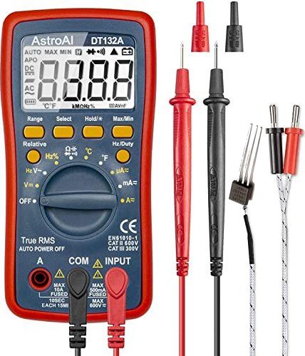
Digitalmultimeter mit Messleitungen
AstroAI DT132A AUTO MAX MIN APO DC AC °C kΩ% mV V Hz/Duty °F Ω Hz% µA mA A= OFF True RMS AUTO POWER OFF EN61010-1 CAT II 600V CAT III 300V A COM INPUT MAX 10A 10SEC EACH 15MIN MAX 500mA FUSED MAX 600V
in „DS18B20 Temperatursensor mit Multimeter messen“ · Mikrocontroller und Digitale Elektronik · · Fotos
-
 Bild
Bild
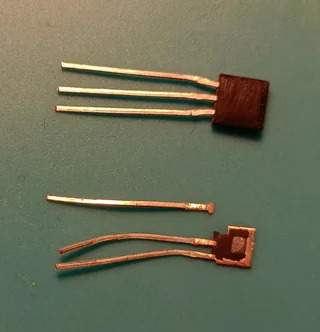
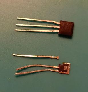
Zwei elektronische Bauteile auf grünem Untergrund
ds18b20-abgefeilt.jpg
in „DS18B20 an Heizungsrohr - wie?“ · Mechanik, Gehäuse, Werkzeug · · Fotos
-
Datei
http.cpp
rtc_temp, ".5"); } strcat (rtc_temp, "°C"); } else { strcpy (rtc_temp, "offline"); } uint_fast8_t ds18xx_is_up = get_numvar (DS18XX_IS_UP_NUM_VAR); if (ds18xx_is_up) { temp_index = get_numvar (DS18XX_TEMP_INDEX_NUM_VAR); sprintf (ds18xx_temp, "%d", temp_index / 2); if (temp_index % 2) { strcat (ds18xx_temp, ".5"); } strcat (ds18xx_temp, "°C"); } else { strcpy (ds18xx_temp, "offline"); } rtc_temperature_correction = get_numvar (RTC_TEMP_CORRECTION_NUM_VAR); if (rtc_temperature_correction) { sprintf (rtc_temperature_correction_str
-
Datei
PLC-LOX.txt
by 100) 13 1st DS2438 Vsens (value multiplied by 100) - 39 DS2438 values (up to 10 sensors) 40-50 DS18B20 Temperature (up to 10 sensors) (value multiplied by 100) Combination of 1wire sensors must be up to 10pcs maximum (DS18B20 or DS2438) using RS485 the UDP syntax must have newline \n symbol at the
in „1 Wire auf 2 GPIO pins“ · Mikrocontroller und Digitale Elektronik ·
-
PDF
AN247.pdf
AN247 DS18x20 EEPROM Corruption Issue www.maxim-ic.com Introduction A shift in device parameters of DS1820B B7 die (used in DS18B20, DS1820S, and DS1822 products) has caused several recent lots to experience EEPROM
in „Billig ds18b20 Fehlverhalten erfahrungen?“ · Mikrocontroller und Digitale Elektronik ·
-
Datei
owaf.c
void) { return mu8_SequencerBusy; } uint8_t owaf_SlaveAck(void) { return mu8_SlaveAck; } void owaf_Ds18b20_TriggerMeasurement(void) { mu8_SequencerBusy = 1u; OneWire_HighLevel(); uint16_t u8_upCount = 0; OneWire_Presence(&u8_upCount); //3 OneWire_WriteByte(&u8_upCount, 0xCC); //2*8 OneWire_WriteByte(&
in „1 Wire manche Teilnehmer antworten nicht“ · Mikrocontroller und Digitale Elektronik ·
-
Datei
onewire.h
void ow_w0(); void ow_w1(); void ow_write(unsigned char data); unsigned char ow_read(); unsigned int ds18b20_read(); void ds18b20_request(); int ds18b20_data(); #endif /* ONEWIRE_H_ */
in „DS18B20 Code funktioniert nicht“ · Mikrocontroller und Digitale Elektronik ·
-
Datei
onewire.h
; void ow_w0(void); void ow_w1(void); void ow_write(uint8_t data); uint8_t ow_read(void); uint8_t ds18b20_read(void); void ds18b20_request(void); uint16_t ds18b20_data(void); #endif /* ONEWIRE_H_ */
in „DS18B20 Code funktioniert nicht“ · Mikrocontroller und Digitale Elektronik ·
-
Datei
Webseite_mit_25_Zeilen.txt
Temperatur, Licht) ablesen</h2><br/> <h2>Temperatur Sensor(Digital):</h2><br/> Temperatur Sensor Außen: ~ds18b20TempOut~ *C<br/> Temperatur Sensor Innen: ~ds18b20TempIn~ *C<br/> Temperatur Sensor Wohnzimmer: ~ds18b20TempLiving~ *C<br/> <h2>Licht Sensor</h2><br/> Licht Sensor Außen: nA lux<br/> Licht Sensor
in „ATMega644 hängt sich auf und resettet sich selbst, nach lesen einer SD Karte und ENC28J60“ · Mikrocontroller und Digitale Elektronik ·
-
Datei
onewire.h
/* ds18b20 lib 0x02 copyright (c) Davide Gironi, 2012 Released under GPLv3. Please refer to LICENSE file for licensing information. References: + Using DS18B20 digital temperature sensor on AVR microcontrollers by Gerard Marull Paretas, 2007 http://teslabs.com/openplayer/docs/docs/other/ds18b20_pre1.pdf */ #ifndef ONEWIRE_H_ #define ONEWIRE_H_ #define Bus_Port PORTB #define Bus_DDR DDRB #define Bus_Pin PINB #define Pin_Nr PB0 #define Bus_Eingang() Bus_DDR &= ~(1<<Pin_Nr) #define Bus_Ausgang
in „Delay mit Timer“ · Mikrocontroller und Digitale Elektronik ·
-
Datei
delay.h
############################################################################### /* Library to use ds18x20 with ATMEL Atmega family. For short ds18x20 wires there is no need for an external pullup resistor. If the wire length exceeds one meter you should use a 4.7k pullup resistor on the data line. This library does not work for parasite power. You can just use one ds18x20 per Atmega Pin. Copyright (C) 2010 Stefan Sicklinger For support check out http://www.sicklinger.com This library is free software: you can redistribute it and/or modify it under the terms of the
in „LCD Anzeige und DS18B20“ · Mikrocontroller und Digitale Elektronik ·
-
Datei
delay.c
############################################################################### /* Library to use ds18x20 with ATMEL Atmega family. For short ds18x20 wires there is no need for an external pullup resistor. If the wire length exceeds one meter you should use a 4.7k pullup resistor on the data line. This library does not work for parasite power. You can just use one ds18x20 per Atmega Pin. Copyright (C) 2010 Stefan Sicklinger For support check out http://www.sicklinger.com This library is free software: you can redistribute it and/or modify it under the terms of the
in „LCD Anzeige und DS18B20“ · Mikrocontroller und Digitale Elektronik ·
-
Datei
PLC-LOX.ino
by 100) 13 1st DS2438 Vsens (value multiplied by 100) - 39 DS2438 values (up to 10 sensors) 40-50 DS18B20 Temperature (up to 10 sensors) (value multiplied by 100) Combination of 1wire sensors must be up to 10pcs maximum (DS18B20 or DS2438) using RS485 the UDP syntax must have \n symbol at the end of
in „1 Wire auf 2 GPIO pins“ · Mikrocontroller und Digitale Elektronik ·
-
Datei
Ds1820_TestProgramm.txt
include <math.h> #include <stdio.h> #include <lcd.h> char lcd_buffer[33]; /* maximum number of DS1820/DS18S20 connected to the 1 Wire bus */ #define MAX_DEVICES 8 /* DS1820/DS18S20 devices ROM code storage area */ unsigned char rom_code[MAX_DEVICES,9]; main() { unsigned char i,j,devices; int temp; lcd_init
in „DS1820 läuft nicht!“ · Mikrocontroller und Digitale Elektronik ·
-
Datei
ds1820.h
wire timing * * 7 5.11.10 22:55 Stadler * - changed driver API * * 6 5.11.10 21:59 Stadler * - added DS18B20 support * - fixed problem with ROM search algorithm * * 5 2.11.10 20:25 Stadler * - changed function DS1820_FindFirstDev to DS1820_FindFirstDevice * - changed function DS1820_FindNextDev to DS1820
-
Datei
PLC-LOX-300-13-12-2019Multibus-2.ino
/* UDP syntax: signals: DS18B20 1wire sensor packet: rail1 1w2 2864fc3008082 temp 25.44 DS2438 1wire sensor packet: rail1 1w2 2612c3102004f 25.44 1.23 0.12 Sensor detected (after start): rail1 1w2 2864fc3008082 detected Sensor
in „1 Wire auf 2 GPIO pins“ · Mikrocontroller und Digitale Elektronik ·
-
Datei
SMR.txt
CONVERT_T 0x44 #define READ_SCRATCHPAD 0xBE #define READ_ROM 0x33 #define MATCH_ROM 0x55 #define DS18B20_FAMILY_CODE 0x28 #define MAX_DEVICES 3 // Maximal erwatete Zahl von Busteilnehmern DS18B20 //Nachfolgend müssen noch zwei Bibliotheks-Dateien korrekt eingebunden werden (bitte Punkte passend ersetzen
in „ROM-Codes als HEX-Zahlen per USART 0 senden“ · Mikrocontroller und Digitale Elektronik ·
-
Datei
ONEWIRE-BOLT.h
//ONEWIRE-BOLT.h //ARCHIVO AUXILIAR CON LAS FUNCIONES PARA LEER LA //TEMPERATURA DEL SENSOR DS18B20 DEL SISTEMA BOLT. //USA EL PIN RA3 PARA CONECTARSE AL DS18B20 //LA FUNCION ds1820_read() REGRESA UN VALOR //DE PUNTO FLOTANTE CON LA TEMPERATURA LEIDA. //NO OLVIDE INSERTAR EL SENSOR DS18B20 EN SU
in „DS18B20 Tempsensor mit PIC18F - Oszillatorprobleme?“ · Mikrocontroller und Digitale Elektronik ·
-
Datei
ds1820.c
************************/ /* */ /* PalmTec - Mikrocontroller-Lernsysteme */ /* */ /* 1-Wire-Bus - DS18S20: */ /* ===================== */ /* */ /* Sammlung der API-Funktionen zum Betrieb des digitalen Temperatursensors DS18S20 */ /* */ /* */ /* */ /* Autoren: P.G. / B.v.B. */ /* */ /* Zielsystem: 8051er-Mikrocontroller
in „Projekt Autoboardcomputer: 12V Schalter, Relais, 1-Wire Temperatursensoren, MOSFET Innenraumbel.“ · Mikrocontroller und Digitale Elektronik ·
-
Datei
Thermometer.txt
deklarieren Ddrd = &B01111111 ' PD0 - PD6 als Ausgang Ddrb = &B00000111 ' PB0 - PB2 als Ausgang ' Pin für DS18B20 Config 1wire = Portd.7 ' Timer deklarieren ' Systemtakt / Prescale = Counts ' 1000000 / 8 = 125000 Config Timer0 = Timer , Prescale = 8 ' Timer0 Overflow Input ' zählt von 0 bis 255 und löst dann
in „DS18B20 auslesen und Temperatur auf 7-Segment-Anzeige ausgeben“ · Mikrocontroller und Digitale Elektronik ·
-
Datei
test1.ino
#include <DallasTemperature.h> OneWire ds(48); //pin für ds18b20 #include <Wire.h> //Speicher Temp float temp1 = 1; float temp2 = 1; float temp3 = 1; float temp4 = 1; float temp5 = 1; void setup(void) { pinMode(13, OUTPUT); Serial.begin(9600); } // HIER must du
in „DS18B20 Verkabelungs od Software Problem“ · Mikrocontroller und Digitale Elektronik ·
-
Datei
DS10-g0133-PID.c
********* // * Datenspeicher 10 * // ******************* // Flüssigkristallanzeige LMK62R125A1 // DS18B20 NR. 13,14,15,16 an 63-10 Adresse 0x18 /************************************************************************/ /* Messstelle 3 = Spannungseingang P6.3 */ /* Messstelle 2 = Spannungseingang P6.2
in „while-Schleife wird "unerlaubt verlassen"“ · Mikrocontroller und Digitale Elektronik ·
-
Datei
gd_user.c
include "rtc_apps.h" #include "gdriver.h" #include "gdisplay.h" #include "gd_user.h" #include "ds1820/ds18x20.h" extern struct sonnenstand Sonne_AUF_UNTER; extern zeit_t Zeit; // rtc.c extern uint8_t gdisp_buf []; extern uint8_t GD_CharBuf[MAX_LINE][MAX_LPOS+1]; extern uint8_t gSensorIDs[5][8]; extern float
in „Grafikfähiger LCD Controller für 320x240 LCD mit 4 Graustufen“ · Projekte & Code ·
-
 Bild
Bild
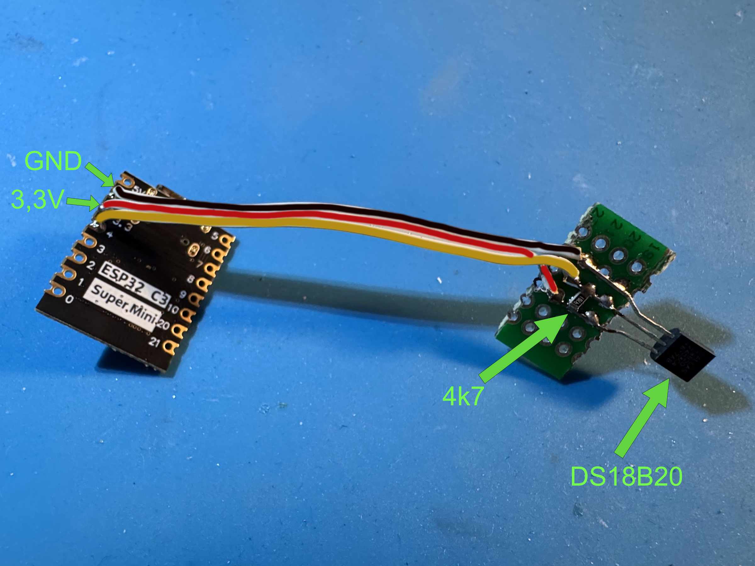
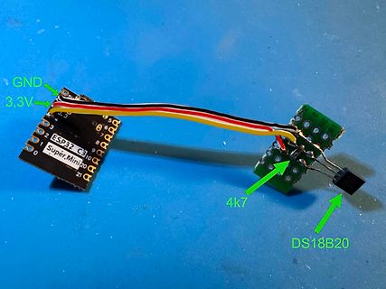
ESP32 Super Mini mit DS18B20 Temperatursensor
GND 3,3V ESP32 C3 Super Mini 20 4k7 DS18B20
in „WiFi Temperatursensor“ · Projekte & Code · · Platinenfotos
-
Datei
familycode10.txt
memory DS1986 0F 64K EPROM memory DS2506 0F 64K EPROM memory DS1820 10 Temperature and alarm trips DS18S20 10 Temperature and alarm trips DS1920 10 Temperature and alarm trips DS2406 12 1K EPROM memory, 2 channel addressable switch DS2407 12 1K EPROM memory, 2 channel addressable switch DS1971 14 256
in „DS1820 DS18s20 Digital Thermometer 1-wire Beispiele ATmega8 Assembler“ · Projekte & Code ·
-
PDF
stm8_uhr.pdf
Digitaluhr mit STM8Sxx3, TM1637, DS18B20 und 6-Digit 7-Segmentanzeige R. Seelig Die hier vorgestellte Uhr ist aus einer Diskussion im Forum www.mikrocontroller.net entstanden innerhalb dieser eine Uhr mit 7-Segmentanzeigen und hoher Ganggenauigkeit
-
Datei
Build_started_28.10.2008_at_15_33_50.txt
DF_CPU=14745600UL -Os -funsigned-char -funsigned-bitfields -fpack-struct -fshort-enums -MD -MP -MT ds18x20.o -MF dep/ds18x20.o. d -c ../1-wire/ds18x20.c avr-gcc.exe -I"D:\www\atmel\webserver\Wil\avr-webserver101\avr-webserver\." -mmcu=atmega644p -Wall -gdwarf-2 -std=gnu99 -DF_CPU=14745600UL -Os -funsigned-char
in „AVR Studio: plugin-Error“ · Mikrocontroller und Digitale Elektronik ·
-
PDF
baerp_17.pdf
D40 16 7 8 DS3 7 8 DS8 DS14 7 8 DS19 7 8 7 8 DS23 7 8 DS28DS34 7 8 3 DS39 7 8 15 DS4 DS9 DS13 DS15DS18 DS24 DS29DS33 D DS38 14 DS5 DS10 DS20 DS25 DS30 DS40 13 12 11 10 8 9 0 1 2 3 4 8 9 0 1 2 3 4 8 9 0 1 2 3 4 8 9 0 1 2 3 4 8 9 0 1 2 3 4 8 9 0 1 2 3 4 8 9 0 1 2 3 4 8 9 0 1 2 3 4 9 1 1 1 1 1 1 1 1 1 1
in „Welcher Transistor“ · Analoge Elektronik und Schaltungstechnik ·
-
Datei
attiny84_24ghz.ino
Tx und Rx Adressen uint8_t MYADDRESS [6] = {"SENSR"}; uint8_t TXADDRESS [6] = {"RECVR"}; // Fuier DS18B20 void setup() { wdt_enable(WDTO_4S); pinMode(LED_ROT,OUTPUT); pinMode(UB_PIN,INPUT); pinMode(LED_GLB,OUTPUT); digitalWrite(LED_GLB,0); digitalWrite(LED_ROT,0); delay(250); digitalWrite(LED_GLB,1);
in „[STM32F4xx] NRF24L01+ Funkmodul Source Code“ · Projekte & Code ·
-
Datei
arduino328.ino
Tx und Rx Adressen uint8_t MYADDRESS [6] = {"SENSR"}; uint8_t TXADDRESS [6] = {"RECVR"}; // Fuier DS18B20 void setup() { wdt_enable(WDTO_4S); pinMode(LED_ROT,OUTPUT); pinMode(UB_PIN,INPUT); pinMode(LED_GLB,OUTPUT); digitalWrite(LED_GLB,0); digitalWrite(LED_ROT,0); delay(250); digitalWrite(LED_GLB,1);
in „Zeigt her eure Kunstwerke (2017-2019)“ · Projekte & Code ·
-
Datei
DS18B20_Temperatur_konvert__.c
[0] / scratchpad.Byte[1]) // Das Ergebnis wird über den globalen String msg[] zurückgegeben. void DS18B20_convert_temperatur(void) { int16_t temp16; uint8_t i = 0; ow_buffer[1] = ow_buffer[1] << 4; // lower nibble im high-Byte nach links schieben // upper nibble im low-Byte nach rechts schieben und /
-
Datei
ds18s20_id_lesen.bas
'******************************************************************************* '* DS18S20 ID Auslesen * '* * '* M.Welnick, 26.01.2009 * '******************************************************************************* $regfile = "m8def.dat" $crystal = 3686400 $baud = 9600 $hwstack = 128
in „AVR für wenig Geld im LAN“ · Mikrocontroller und Digitale Elektronik ·
-
Datei
AVR_T_DS18S20.cpp
///////////////////////////////////////////////////////// // // Time-stamp: "25.12.09 22:59 AVR_T_DS18S20.cpp klaus?wachtler.de" // //////////////////////////////////////////////////////////////////////////////// // // Beispiel für Anschluß Temperatursensor DS18S20 (1-wire) an ATMega32 // // Zudem verwendet
in „DS18S20 Temperatur auslesen mit C geht nicht“ · Mikrocontroller und Digitale Elektronik ·
-
Datei
DS18B20_go1.bas
$regfile = "m32def.dat" $crystal = 16000000 $swstack = 50 $hwstack = 50 $framesize = 50 '===================== Pinkonfiguration ===================== Config Lcdpin = Pin , Db4 = Portc.4 , Db5 = Portc.5 , Db6 = Portc.6 , _ Db7 = Portc.7 , E = Portc.3 , Rs = Portc.2 Config Lcd = 16 * 4 Config 1wire = Portd.5 Cls Cursor Off '=================== Variablendeklaration =================== Dim Scratchpad As Integer 'Integer für Scratchpadinhalt Dim Temp As Single 'Variable für Temperaturausgabe in Dezimal Dim I As Byte 'Zählervariable '============== 1wire-Bus ansprechen/auslesen =============== Do 1wreset
in „DS18B20 - Zwei Routinen zum checken“ · Mikrocontroller und Digitale Elektronik ·
-
Datei
DS18B20_go2.bas
$regfile = "m32def.dat" $crystal = 16000000 $swstack = 50 $hwstack = 50 $framesize = 50 '===================== Pinkonfiguration ===================== Config Lcdpin = Pin , Db4 = Portc.4 , Db5 = Portc.5 , Db6 = Portc.6 , _ Db7 = Portc.7 , E = Portc.3 , Rs = Portc.2 Config Lcd = 16 * 2 Config 1wire = Portd.5 Cls Cursor Off '=================== Variablendeklaration =================== Dim Scratchpad1(9) As Byte 'Array für Scratchpadinhalt Dim Tmp1 As Byte 'Variable zum Auslesen der ersten beiden Arraybytes Dim T1 As Integer 'Zwischenvariable zur Berechnung Dim Temp1 As Single 'Variable für Temperaturausgabe
in „DS18B20 - Zwei Routinen zum checken“ · Mikrocontroller und Digitale Elektronik ·
-
Datei
Atmega16_DS18S20.c
#include <avr/io.h> #include <avr/interrupt.h> #define F_CPU 8000000 //-> bereits unter Project->Configuration Options-> als 8000000 definiert #include <util/delay.h> #include <inttypes.h> #include <stdint.h> #define TRUE 1 #define FALSE 0 // Anchlussbelegung: An welchen Pins h?ngt der DS1820 bzw die LED Anzeige #define W1_PIN PC0 //PC0 Pin soll der W1_PIN sein - in diesem Fall ist es der DataPin vom DS1820 #define W2_PIN PC1 //PC0 Pin soll der W1_PIN sein - in diesem Fall ist es der DataPin vom DS1820 #define W1_IN PINC //Pin abfragen #define W1_OUT PORTC //Ausg?nge ansteuern #define W1_DDR DDRC
in „Thermomixer noch einmal neu - dieses mal nur ein MEGA16“ · Mikrocontroller und Digitale Elektronik ·
-
Datei
DS18B20_GETADDRESS.a51
$include(AT89S53.inc) ;main2: ; setb p1.0 ; call delay1s ; clr p1.0 ; call delay1s ; jmp main2 main: clr p1.1 ; trigger bedingung setb p1.1 ; call readRom call addressOut jmp main addressOut: mov r1,#8 mov r0,#80h write8BytesLoop_2: mov p0,@r0 inc r0 call delay1s djnz r1, write8BytesLoop_2 ret ;------------------------------------------------------------------------ ;1-wire functions ;------------------------------------------------------------------------ ; sends a RESET and waits 240µs for a PRESENCE ; - pull bus LOW for 480µs ; - release bus ; - wait 70µs ; - read bus state ; - wait 410µs ;
in „Timing Probleme 1-Wire“ · Mikrocontroller und Digitale Elektronik ·
-
PDF
DS18S20_RS232.pdf
T2OUT T2IN 12 1 D111 3 Eingang R1IN R1OUT Ausgang 1 GND PL101-3 TXD Eingang8 R2IN R2OUT 9 9 1N4148 DS18S20 GND PL101-7 RTS MAX232 B GND B PL101-9 RI PL101-10 +5V X101 1 B 2 S 3 U 4 GND PN61729-S C C +5V 1C V IC101P C105 D 5G X7R-G1206 10/16 1 D D M. Pabelick GND 1 2 3 4 5 6
in „Temperaturmessung DS18S20 mit MAX232 über Serielle Schnittstelle“ · Mikrocontroller und Digitale Elektronik ·
-
PDF
DS18S20_Romcode_einlesen.pdf
Presence - Impuls Presence Impuls erstes Byte 0 0 0 0 1 0 0 0 LSB MSB 0 1 = 10h Leserichtung zweites Byte 0 1 1 1 0 1 1 0 LSB MSB E 6 = 6Eh Leserichtung drittes Byte 0 0 1 1 0 1 1 0 LSB MSB C 6 = 6Ch Leserichtung viertes Byte 1 0 1 1 1 0 1 1 MSB LSB D D = DDh Leserichtung fünftes Byte 1 0 0 0 0 0 0 0 LSB MSB 1 0 = 01h Leserichtung sechstes Byte 0 0 0 1 0 0 0 0 LSB MSB 8 0 = 08h Leserichtung siebtes Byte 0 0 0 0 0 0 0 0 LSB MSB 0 0 = 00h Leserichtung achtes Byte 0 1 0 1 1 0 1 0 LSB MSB A 5 = 5Ah Leserichtung Gesamter Romcode lautet: 10 6E 6C DD 01 08 00 5A 8-BIT FAMILY CODE (10h) 48-BIT SERIAL
in „DS18S20 auslesen (finde den fehler nicht)“ · Mikrocontroller und Digitale Elektronik ·
-
PDF
DS18S20_Romcode_einlesen_.pdf
Presence - Impuls Presence Impuls erstes Byte 0 0 0 0 1 0 0 0 LSB MSB 0 1 = 10h Leserichtung zweites Byte 0 1 1 1 0 1 1 0 LSB MSB E 6 = 6Eh Leserichtung drittes Byte 0 0 1 1 0 1 1 0 LSB MSB C 6 = 6Ch Leserichtung viertes Byte 1 0 1 1 1 0 1 1 MSB LSB D D = DDh Leserichtung fünftes Byte 1 0 0 0 0 0 0 0 LSB MSB 1 0 = 01h Leserichtung sechstes Byte 0 0 0 1 0 0 0 0 LSB MSB 8 0 = 08h Leserichtung siebtes Byte 0 0 0 0 0 0 0 0 LSB MSB 0 0 = 00h Leserichtung achtes Byte 0 1 0 1 1 0 1 0 LSB MSB A 5 = 5Ah Leserichtung Gesamter Romcode lautet: 10 6E 6C DD 01 08 00 5A 8-BIT FAMILY CODE (10h) 48-BIT SERIAL
in „DS18S20 auslesen (finde den fehler nicht)“ · Mikrocontroller und Digitale Elektronik ·
-
Datei
ds1820.h
0xBE #define DS1820_CMD_COPYSCRPAD 0x48 #define DS1820_CMD_RECALLEE 0xB8 #define DS1820_FAMILY_CODE_DS18B20 0x28 #define DS1820_FAMILY_CODE_DS18S20 0x10 /* ---------------------------------------------------------------------------- */ /* LED1 and LED2 Definitions */ /* --------------------------------
in „ds18b20 temperaturmessung mit pic18f4550“ · Mikrocontroller und Digitale Elektronik ·
-
Datei
Tempsensor_Test_Fred.txt
Test-Platine ************************ '* ist ein Testmodul für Digital Temperatur-Sensoren * '* [DS18x20] DS18S20 ist ein 9 Bit Family Adr &H10 * '* und DSB20 ein 12 Bit Family Adr &H28 * '* somit große Unterschiede bei der "Empfindlichkeit" * '* Das lesen der Bit's ist somit auch Unterschiedlich. *
in „DS1820 Auslese Fehler“ · Mikrocontroller und Digitale Elektronik ·
-
PDF
PSU.pdf
r tin_Headers:Pin_Header5StraightN1x08 r 0 _ R s R7 s i 8 R 1 i (PCINT16/RXD)PD0 30 StatusLEDMCU DS18B20 l S N i 2 D DAC_Spannung d R d d R R R 31 S H r 6 O e C-3 NPN S Resistors_SMD:R_0805_HandSolderinr S D i (PCINT17/TXD)PD1 a S e 7 C R O r a a l Spannung_st n S d 32 r _ U a T B gi _ _ d Housings_SOIC
in „Labornetzteil“ · Analoge Elektronik und Schaltungstechnik ·
-
Datei
ds1820.ASM
;programm für 2313 @ 8MHz zur ansteuerung eines ds18s20-temp-sensors (bzw ds1820) ;anschluss des ds18s20an pind0 ;an den ds1820 müss noch ein pull-up widerstand von 4,7kohm nach +5V ; angeschlossen werden .include "d:\avr\2313def.inc" .def befehl = r0
in „DS18S20 Temperatur-Sensor“ · Mikrocontroller und Digitale Elektronik ·
-
Datei
DS1820.txt
;programm für 2313 @ 8MHz zur ansteuerung eines ds18s20-temp-sensors (bzw ds1820) ;anschluss des ds18s20an pind0 ;an den ds1820 müss noch ein pull-up widerstand von 4,7kohm nach +5V ; angeschlossen werden .include "d:\avr\2313def.inc" .def befehl = r0
in „Programmänderung DS1820“ · Mikrocontroller und Digitale Elektronik ·